Note: Descriptions are shown in the official language in which they were submitted.
CA 02739565 2015-12-22
76433-158
ACTUATOR FOR SPRAY CONTAINER
AND METHOD REGARDING SAME
CROSS-REFERENCE TO RELATED APPLICATIONS
[01] This application claims the benefit of "U.S. Provisional Application
Serial
No. 61/103,059 filed 6,0ctober 2008, entitled "ACTUATOR FOR SPRAY
CONTAINER."
BACKGROUND
[02] The disclosure herein relates generally to actuators for spray
containers and
methods of manufacturing actuators for spray containers.
[03] Spray containers containing many different components or contents such
as,
e.g., paint, adhesives, corrosives, lubricants, insect repellents, hairsprays,
creams, edibles, foams, etc. have been marketed for many household,
commercial, and industrial purposes.
[04] In certain conventional spray containers, an actuator apparatus may
include a
tubular valve stem element biased into a closed position which, when depressed
into the body of the container opens the valve and releases the contents which
are held under pressure. When the applied force at the valve stem is removed,
the valve stem returns to its closed position simultaneously stopping the
outward
flow of the pressurized contents of the container. For example, in one type of
spray container, the actuator apparatus may include a button fitted directly
over
the valve stem such that when the button is depressed, the valve stem is
simultaneously depressed or tilted against a spring bias causing the contents
of
the container to be released via an outlet. Release of the pressure at the
button
returns the valve stem to its equilibrium position. Often, a protective cover
is
fitted over the top of the spray container covering the actuator apparatus and
is
removed before use. Such protective covers may then be placed back over the
actuator apparatus, e.g., for safe storage.
-1-
CA 02739565 2011-04-05
WO 2010/042431
PCT/US2009/059513
[05] In another type of spray container, an actuator apparatus may include
a cap
having a button or trigger. By depressing the button or trigger, the contents
of
the spray container may be sprayed, e.g., through an opening in the cap.
Often,
the button or trigger is not protected from accidental depression by a user.
[06] Lockable actuator apparatuses have been described. For example, U.S.
Pat.
No. 6,523,722 to Clark et al., U.S. Pat. App. Pub. No. 2005/0017027 to Yerby
et
al., and U.S. Pat. App. Pub. No. 2007/0039979 to Strand et al. disclose
various
lockable actuators for spray containers. However, such designs may include
many separate components and/or may be too complex such that the components
and/or complexity may increase manufacturing problems (e.g., complex multi-
piece molds, etc.), which may increase the cost of such actuators.
SUMMARY
[07] The disclosure herein relates generally to actuators for spray
containers and
methods of manufacturing actuators for spray containers.
[08] In one embodiment of the actuator apparatus for a spray container, the
actuator apparatus includes a base and a cover coupled to the base. The base
includes a lower portion couplable to the spray container and a push button
depressibly attached to the lower portion. The push button includes a body
portion, an aperture portion, and a receiver stem for receiving a valve
assembly.
The body portion extends along an axis of the actuator apparatus between a
first
end region connectable to the lower portion of the base and a second end
region
to be contacted for depression of the push button by a user. The aperture
portion
extends radially from a region of the body portion and defmes an exit
aperture.
The receiver stem portion defines an entrance aperture. A fluid passageway
extends between the entrance aperture and the exit aperture. Further, the push
button is movable relative to the lower portion of the base between at least a
nolinal position and a depressed position. When the push button is in the
depressed position, the push button actuates the valve assembly to provide a
spray through the exit aperture. The cover defines a push button opening that
permits access to the second end region of the body portion of the push button
to
allow depression of the push button by the user. Further, the cover and the
base
-2-
CA 02739565 2011-04-05
WO 2010/042431 PCT/US2009/059513
are movable relative to each other between at least a locked position such
that
the push button is restricted from moving into the depressed position and an
unlocked position such that the push button is allowed to move into the
depressed position. The cover further defines a spray opening alignable with
the
exit aperture of the aperture portion when the cover is in the unlocked
position.
Further, the cover includes a restraint structure and the restraint structure
is
located below the aperture portion of the push button of the base to restrict
the
push button from moving into the depressed position when the cover is in the
locked position.
[09] In another embodiment, the actuator apparatus for a spray container
includes
a base and a cover coupled to the base. The base includes a lower portion
couplable to the spray container and a push button depressibly attached to the
lower portion. The push button includes a body portion and an aperture
portion.
The body portion extends between a first end region connectable to the lower
portion of the base and a second end region to be contacted for depression of
the
push button by a user. The aperture portion extends radially from a region of
the
body portion. Further, the push button is movable relative to the lower
portion
of the base by depression of the push button by the user. Still further, the
aperture portion defines an exit aperture. The cover defines a push button
opening that permits access to the second end region of the body portion to
allow
depression of the push button by the user. Also, the cover and the base are
rotatably movable relative to each other between an unlocked position and a
locked position. The cover includes a cylindrical inner wall portion lying
parallel to an axis of the actuator apparatus and the cylindrical inner wall
portion
defines at least a portion of the push button opening. The cover further
includes
a restraint structure locatable below the aperture portion of the push button
of the
base to restrict the push button from depression by the user when in the
locked
position. Further, at least a portion of the restraint structure is located
closer to
the axis of the actuator apparatus than the cylindrical inner wall portion of
the
cover. Still further, the cover defines a spray opening alignable with the
exit
aperture by rotating the cover and the base relative to each other when in the
unlocked position.
-3-
CA 02739565 2011-04-05
WO 2010/042431
PCT/US2009/059513
[101 In one embodiment, a method of manufacturing a cover for an
actuator
apparatus having a base including a lower portion and a centrally-located push
button depressibly attached to the lower portion is described. The method of
manufacturing includes providing a mold defming a cavity for foiming the
cover. The cover defines a centrally-located push button opening that permits
access to the push button of the base when assembled with the base. Further,
the
cover includes an inner wall portion, an outer wall portion, and a restraint
structure extending from the inner wall portion. The inner wall portion lies
along an axis of the actuator apparatus when assembled with the base and
defines at least a portion of the push button opening. The outer wall portion
is
located at a distance further away from the axis than the inner wall portion
when
assembled with the base and defmes a spray opening. The restraint structure
extends from the inner wall portion and at least a portion of the restraint
structure is located closer to the axis of the actuator apparatus when
assembled
than the inner wall portion of the cover. The mold includes a first mold
portion
and a second mold portion. The first mold portion defines a first molding
surface corresponding to at least outer and inner wall portion surfaces of the
cover facing a first direction and at least a lower surface of the restraint
structure.
The second mold portion defines a second molding surface corresponding to at
least outer and inner wall portion surfaces of the cover facing a second
direction
opposite from the first direction and at least an upper surface of the
restraint
structure. The method further includes positioning the first mold portion
relative
to the second mold portion such that the first molding surface of the first
mold
portion and the second molding surface of the second mold portion define the
cavity of the mold for forming the cover and introducing moldable material
into
the cavity of the mold. Still further, the method includes forming the cover
from
the moldable material within the cavity of the mold, moving the first mold
portion relative to the second mold portion for removing the cover from the
cavity of the mold, and removing the cover from the cavity of the mold.
[111 The above summary is not intended to describe each embodiment or
every
implementation of the actuator apparatus or methods of manufacturing such
actuator apparatus. Advantages, together with a more complete understanding,
-4-
CA 02739565 2011-04-05
WO 2010/042431
PCT/US2009/059513
will become apparent and appreciated by referring to the following detailed
description and claims taken in conjunction with the accompanying drawings.
BRIEF DESCRIPTION OF THE DRAWING
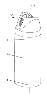
[12] FIG. 1 is a front perspective view of a spray container and an
exemplary
embodiment of an actuator apparatus in an unlocked position.
[13] FIG. 2 is a rear perspective view of the spray container and the
actuator
apparatus of FIG. 1 in the unlocked position
[14] FIG. 3 is a front perspective view of the spray container and the
actuator
apparatus of FIG. 1 but in a locked position.
[15] FIG. 4 is a rear perspective view of the spray container and the
actuator
apparatus of FIG. 1 but in a locked position.
[16] FIG. 5 is an exploded, perspective view of the actuator apparatus of
FIG. 1.
[17] FIG. 6 is a perspective view of the base of the actuator apparatus of
FIG. 1.
[18] FIG. 7 is a front view of the base of FIG. 6.
[19] FIG. 8 is a side view of the base of FIG. 6.
[20] FIG. 9 is a rear view of the base of FIG. 6.
[21] FIG. 10 is atop view of the base of FIG. 6.
[22] FIG. 11 is a bottom view of the base of FIG. 6.
[23] FIG. 12 is a front perspective view of the cover of the actuator
apparatus of
FIG. 1.
[24] FIG. 13 is a front view of the cover of FIG. 12.
[25] FIG. 14 is a side view of the cover of FIG. 12.
[26] FIG. 15 is a rear view of the cover of FIG. 12.
-5-
CA 02739565 2011-04-05
WO 2010/042431
PCT/US2009/059513
[27] FIG. 16 is a top view of the cover of FIG. 12.
[28] FIG. 17 is a bottom view of the cover of FIG. 12.
[29] FIG. 18 is a rear perspective view of the cover of FIG. 12.
[30] FIG. 19 is a bottom perspective view of the cover of FIG. 12.
[31] FIG. 20 is a cross-sectional view of the cover of FIG. 16 taken along
line 20-
20.
[32] FIG. 21 is a front view of the actuator apparatus of FIG. 1 but in a
locked
position.
[33] FIG. 22 is a cross-sectional view of the actuator apparatus of FIG. 21
taken
along line 22-22.
[34] FIG. 23 is top view of the actuator apparatus of FIG. 1 but in a
locked
position.
[35] FIG. 24 is a cross-sectional view of the actuator apparatus of FIG. 23
taken
along line 24-24.
[36] FIG. 25 is a front view of the actuator apparatus of FIG. 1 in an
unlocked
position.
[37] FIG. 26 is a cross-sectional view of the actuator apparatus of FIG. 25
taken
along line 26-26.
[38] FIG. 27 is a top view of the actuator apparatus of FIG. 1 in an
unlocked
position.
[39] FIG. 28 is a cross-sectional view of the actuator apparatus of FIG. 27
taken
along line 28-28 with the push button in a normal position.
[40] FIG. 29 is a cross-sectional view of the actuator apparatus of FIG. 27
taken
along line 28-28 with the push button in a depressed position.
-6-
CA 02739565 2011-04-05
WO 2010/042431
PCT/US2009/059513
[41] FIGS. 30A-30C are cross-sectional views illustrating assembly of the
actuator apparatus of FIG. 1.
[42] FIG. 31 is a block diagram of a method of manufacturing a cover, e.g.,
the
cover of FIG. 12, for an actuator apparatus.
[43] The figures are rendered primarily for clarity and, as a result, are
not
necessarily drawn to scale.
DETAILED DESCRIPTION OF EXEMPLARY EMBODIMENTS
[44] In the following detailed description of illustrative embodiments,
reference is
made to the accompanying figures of the drawing which form a part hereof, and
in which are shown, by way of illustration, specific embodiments which may be
practiced. It is to be understood that other embodiments may be utilized and
structural changes may be made without departing from the scope of the
disclosure.
[45] A spray container 5 is shown in FIGS. 1-4 extending from a bottom
portion 6
to a top portion 7 along an axis 12. An exemplary actuator apparatus 10 is
coupled to the top portion 7 of the spray container 5. The spray container 5
(e.g.,
a cylindrical spay can) may be any spray container containing a pressurized
material that may be actuated by a user to release (e.g., spray) the
pressurized
contents from an opening. Further, the spray container 5 may contain many
different liquid materials such as, e.g., paint, adhesives, corrosives,
lubricants,
insect repellents, hairsprays, creams, edibles, foams, tear gas, pepper spray,
and/or any other contents as would be known by one having ordinary skill in
the
art. Also, the spray container 5 may be formed of any material capable of
containing its contents under pressure, e.g., metals, polymers, etc.
[46] As shown in FIGS. 1-4, the spray container 5 includes a cylindrical
can.
Although the spray container 5 depicted in FIGS. 1-4 is cylindrical, the
actuator
apparatus may be operably coupled to a spray container having any shape and/or
size, e.g., a square container.
-7-
CA 02739565 2011-04-05
WO 2010/042431 PCT/US2009/059513
[47] Two or more components of the actuator apparatus 10 are movable
relative
to each other between two or more different positions. A locked position is
depicted in FIGS. 1-2 while an unlocked position is depicted in FIGS. 3-4. In
the unlocked position, the actuator apparatus 10 may allow a user to release
at
least some of the pressurized contents contained in the spray container 5. In
the
locked position, the actuator apparatus 10 may restrict (e.g., inhibit) a user
from
releasing the pressurized contents contained within the spray container 5.
[48] An exploded view of an exemplary embodiment of the actuator apparatus
10
arranged along an axis 12 is depicted in FIG. 5. The actuator apparatus 10 may
include a base 100, a cover 200, an insert 300, and a valve assembly 400.
[49] The valve assembly 400 may include an actuation valve 402, a flanged
cup
portion 404, and a tube portion 406. When assembled with the spray container
5, the flanged cup portion 404 may be coupled (e.g., crimped, press-fit,
adhered,
welded, etc.) to at least a portion of the top of the spray container 5, the
tube
portion 406 may extend into the interior of the spray container 5, and the
actuation valve 402 may extend upward from the top of the spray container 5.
The actuation valve 402 and flanged cup portion 404 may further include
various
structures to operably couple the actuation valve 402 to a portion of the base
such that any pressurized contents released through the actuation valve 402
flow
into a portion of the base 100 (e.g., through passageway 174 as shown in FIG.
28). The flanged cup portion 404 may include a centrally-disposed circular
stepped protrusion 408 upon which the actuation valve 402 extends. Such
stepped protrusion 408 may include portions having different diameters that
may
improve the coupling between the valve assembly 400 and the base 100. In at
least one embodiment, the components of the valve assembly 400 may be
founed of the same material. In other embodiments, the components of the
valve assembly 400 may be separate components coupled together.
[50] The actuation valve 402 may be movable to, e.g., release the
pressurized
contents of a spray container (e.g., spray container 5). Such movement of the
actuation valve 402 may be downward depression, axially movement, etc.
-8-
CA 02739565 2011-04-05
WO 2010/042431 PCT/US2009/059513
[51] One having ordinary skill in the art will recognize that other valve
configurations may be utilized with the apparatus described herein. For
example, any valve assembly operable by a push button as described herein to
release contents of a spray container may be utilized in conjunction with the
actuator apparatus 10 or variations thereof.
[52] The base 100 may include a lower portion 120 and a push button 140
(see
FIGS. 6-11). The push button 140 may be depressibly attached to the lower
portion 120. As used herein, "depressibly attached" may refer to attachment
such that the push button 140 may be depressed under normal force by a user to
move the push button 140 relative to the lower portion 120.
[53] The lower portion 120 may include a first end region 121A and a second
end
region 121B located further away from the axis 12 than the first end region
121A. The second end region 121B may be the portion of the base 100 that is
coupleable to the spray container 5 utilizing, e.g., one or more protrusions
122
(see FIG. 11) that may facilitate a "snap-fit" to the top of the spray
container 5.
Further, the lower portion 120 may define a push button aperture 124 located
directly below the push button 140 to facilitate downward movement of the push
button 140 (e.g., such that when the push button 140 is depressed, at least a
portion of the push button 140 may be located within the push button aperture
124).
[54] As shown in FIGS. 10-11, the lower portion 120 may include a bridge
portion 126 connecting the lower portion 120 and the push button 140. The
bridge portion 126 may be sized and formed of such resilient material that the
push button 140 may be depressed to a depressed position (e.g., movement
relative to the lower portion 120) and returned to a normal position without
detaching from the lower portion 120.
[55] Further, the push button 140 may be biased into the normal position
such that
only depression by a user may actuate the valve assembly 400 to release at
least
some of the pressurized contents of the spray container 5. The bridge portion
126 may provide such bias. In other embodiments, however, the push button
-9-
CA 02739565 2011-04-05
WO 2010/042431 PCT/US2009/059513
140 may include other componentry (e.g., springs), materials (e.g., memory
foam), and/or structures that may bias the push button into the normal
position.
[56] The lower portion 120 may further include a first female locking
structure
128, a second female locking structure 130, a spray opening shield portion
132,
and deflectable cover retention ribs 134 that will be described herein in
relation
to their functions relative to the push button 140 and cover 200.
[57] The push button 140 may include a body potion 142, an aperture portion
160, and a receiver stem portion 170 (see FIG. 11). Although depicted as being
cylindrical, the push button 140 may be any shape and/or size operable to be
depressed by a user to actuate a valve assembly, e.g., valve assembly 400. The
push button 140 may be movable relative to the lower portion 120 of the base
100 between at least a normal position and a depressed position. When the push
button 140 is in the depressed position (which is only permitted when the
actuator assembly is in the unlocked position), the push button 140 may
actuate
the actuation valve 402 of the valve assembly 400 thereby releasing at least
some
of the pressurized contents of the spray container 5 through, e.g., an exit
aperture
162 of the aperture portion 160 of the push button 140 of the base 100. When
the push button 140 is in the normal position, the valve assembly 402 is not
actuated and thereby no pressurized contents are released.
[58] The body portion 142 of the push button 140 may extend along an axis
12 of
the actuator apparatus 10 from a first end region 144 that is connectable to
the
lower portion 120 of the base 100, e.g., via the bridge portion 126 of the
lower
portion 120 of the base 100, to a second end region 146 that may be contacted
(e.g., depressed by a finger) by a user. The second end region 146, as
depicted,
may define a sloped, concave surface 148, upon which further may be defined
spray direction indicia 150 to, e.g., indicate the direction that the
pressurized
contents of the spray container may be released and/or whether the actuator
apparatus 10 is in a locked or unlocked position. The sidewalls of the body
142
may cylindrical, e.g., as depicted, and further may be parallel to the axis 12
of
the actuator apparatus 10.
-10-
CA 02739565 2011-04-05
WO 2010/042431 PCT/US2009/059513
[59] The aperture portion 160 may extend radially (e.g., outwardly from the
axis
12 of the actuator apparatus) from a region of the body portion 142 (e.g., the
side
wall thereof) and may define the exit aperture 162. When the pressurized
contents are released from the spray container 5, the contents may be released
(e.g., sprayed) through the exit aperture 162. In the embodiment depicted, the
aperture portion 160 includes an insert aperture 166 within which the insert
300
is located. The insert 300 may be a separately manufactured component from
the base 100 or may be integral with the base 100. For example, the insert 300
may be a molded feature of the aperture portion 160. As described herein, the
insert 300 may be a part of the aperture portion 160 of the push button 140 of
the
base 100.
[60] Further, at least in one embodiment, the aperture portion 160 extends
along a
portion of the height of the push button body portion 142. Also, the aperture
portion 160 may have a lower surface 164 that be contacted by, e.g., a
restraint
structure (e.g., restraint structure 204 of FIGS. 18-19) to restrict the
downward
movement of the push button 140 as described herein. Although aperture
portion 160 is depicted as having a lower surface 164 that is flat, the
aperture
portion 160 may be any size and/or shape capable of being contacted by a
corresponding restraint structure (e.g., by restraint structure 204 of FIGS.
18-19)
to restrict the movement of the push button 140.
[61] Further, although in this embodiment, the aperture portion 160 is the
portion
of the push button 140 that may be contacted by a restraint structure (e.g.,
by
restraint structure 204) to restrict the movement of the push button 140, the
aperture portion may be separate from the portion the may be contacted to
restrict movement of the push button. For example, in at least one embodiment,
the aperture portion may not extend from the push button body portion and
instead may be flush with the exterior of the push button body. In this
embodiment, an additional structure may extend radially from the push button
body portion to be contacted by a restraint structure to restrict the movement
of
the push button.
-11-
CA 02739565 2011-04-05
WO 2010/042431 PCT/US2009/059513
[62] The receiver stem portion 170 (see FIG. 11) may receive the valve
assembly
400 and may define an entrance aperture 172. A passageway 174 may be
capable of transmitting gas and/or fluid and may extend from the entrance
aperture 172 to the exit aperture 162 of the aperture portion 160. When the
actuation valve 402 is actuated, the pressurized contents of the spray
container 5
may released and may flow through the valve assembly 400 into the entrance
aperture 172, through the passageway 174, and exit through the exit aperture
162.
[63] The base 100 may further include locked and unlocked indicia 102
located
on various surfaces of its components to indicate to a user what state the
actuator
apparatus 10 is in (e.g., unlocked or locked positions). Although the indicia
102
are depictions of a "locked padlock" and an "unlocked padlock," any indicia
including graphics and/or text that may be capable of indicating to a user the
state of the actuator apparatus may be included on the actuator apparatus. For
example, the spray opening shield portion 132 may extend upwardly from the
base 100 and may include such indicia 102. In this embodiment, the spray
opening shield portion 132 has indicia 102 indicating that the actuator
apparatus
is in a locked state, which is only viewable to user when the actuator
apparatus 10 is actually in a locked state or position as described herein.
[64] In one or more alternate embodiments, the spray opening shield portion
132
may not be used. Rather, the locked indicia may be provided on the push button
body portion 142 such that it shows through the opening 208 when the apparatus
is in a locked position.
[65] The cover 200, or shroud, may be coupled to the base 100 and aligned
along
an axis 12 of the actuator apparatus 10. The cover 200 may define a push
button
opening 202 (e.g., along axis 12) that permits access to the second end region
146 of the push button 140 to allow depression (e.g., by a finger) of the push
button 140 by a user when the base 100 and the cover 200 are assembled
together (see, e.g., FIGS. 1-2, 25, & 27-29).
[66] The cover 200 (as shown in FIGS. 12-20) may be coupled (e.g.,
rotatably
coupled) to the base 100 to allow movement there between. At least in one
-12-
CA 02739565 2011-04-05
WO 2010/042431 PCT/US2009/059513
embodiment, the cover 200 is rotatable relative to the base 100 between a
locked
position such that the push button 140 is restricted from moving into the
depressed position and an unlocked position such that the push button 140 may
be allowed to move into the depressed position. The cover 200 may include a
restraint structure 204 that restricts the push button 140 from moving into
the
depressed position when the base 100 and/or cover 200 is in the locked
position.
Further, the restraint structure 204 may define an upper surface 206 and a
lower
surface 209 (see FIG. 19). When the base 100 and/or cover 200 is in the locked
position, the restraint structure 204 may be located below the aperture
portion
160 of the push button 140 of the base 100 to physically restrict the aperture
portion 160 from moving downwardly, which in turn restricts the other portions
of the push button 140 from moving into the depressed position. In other
words,
the upper surface 206 of the restraint structure 204 may directly contact the
lower surface 164 of the aperture portion 160 of the push button 140 of the
base
100 to restrict the movement of the push button 140 into the depressed
position.
[67] In at least one embodiment, the cover 200 may include one or more
restraint
structures. However, as depicted, the cover 200 includes only one restraint
structure 204.
[68] The cover 200 may further define a spray opening 208 that may be
alignable
with the exit aperture 162 of the aperture portion 160 of the push button 140
of
the base 100 when the cover 200 is in the unlocked position. The cover 200 may
further include an inner wall portion 210 lying along the axis 12 of the
actuator
apparatus 10 and an outer wall portion 230 located further away from the axis
12
than the inner wall portion 210. The inner wall portion 210 may further
include
inside surface 222 and an exterior surface 224. The inner wall portion 210, as
depicted, may by cylindrical to, e.g., define at least a portion of the push
button
opening 202. In other embodiments, however, the inner wall portion 210 may be
any shape or size to accommodate and permit depressible movement of at least a
portion of the push button 140. Further, the restraint structure 204 may be
located closer to the axis 12 of the actuator apparatus 10 than the inner wall
portion 210 (see FIG. 16).
-13-
CA 02739565 2011-04-05
WO 2010/042431
PCT/US2009/059513
[69] The inner wall portion 210 of the cover 200 may further define a first
stop
surface 212 and a second stop surface 214. The first stop surface 212 may be
operable with the aperture portion 160 of the base 100 to stop the cover 200
and
base 100 from moving (e.g., rotating about axis 12) past the unlocked
position.
For example, a first side surface 165A of the aperture portion 160 may contact
the first stop surface 212 to stop the cover 200 from rotating relative to the
base
100. When the first side surface 165A of the aperture portion 160 contacts the
first stop surface 212, the aperture apparatus 10 is in the unlocked position.
[70] The second stop surface 214 may be operable with the aperture portion
160
of the base 100 to stop the cover 200 and base 100 from moving past the locked
position. For example, a second side surface 165B of the aperture portion 160
may contact the second stop surface 214 to stop the cover 200 from rotating
relative to the base 100. When the second side surface 165B of the aperture
portion 160 contacts the second stop surface 214, the aperture apparatus 10 is
in
the locked position.
[71] The outer wall portion 230 may further define interior surface 242 and
exterior surface 244. Further, the outer wall portion 230 may include a male
locking structure 232 located on a portion of the interior surface 242 of the
outer
wall portion 230. The male locking structure 232 may engage either of the
first
female locking structure 128 (when in the locked position) or the second
female
locking structure 130 (when in the unlocked position) of the base 100 when the
base 100 and the cover 200 are assembled to form the actuator apparatus 10.
[72] Each of the female locking structures 128, 130 may include a first rib
129A,
129B and second rib 131A, 131B, respectively. Each rib 129A, 129B, 131A,
131B may extend outwardly from the lower portion 120 of the base 100 for
engagement with the male locking structure 232 of the outer wall portion 230
of
the cover 200.
[73] The male locking structure 232 of the outer wall portion 230 of the
cover 200
may include a deflectable portion 234 for deflectably engaging the first rib
129A
of the first female locking structure 128 of the lower portion 120 of the base
100
when the cover 200 is moving into the locked position (e.g., such as to make a
-14-
CA 02739565 2011-04-05
WO 2010/042431 PCT/US2009/059513
"click" when moving into the locked position) and for deflectably engaging the
first rib 129B of the second female locking structure 130 of the lower portion
120 of the base 100 when the cover 200 is moving into the unlocked position
(e.g., such as to make a "click" when moving into the unlocked position). The
deflectable portion 234 may deflect to provide resistance to moving the cover
200 relative to the base 100 so as to signal or indicate to a user that the
cover 200
may almost be moved (relative to the base 100) into either a locked or
unlocked
position. The cover 200 may be moved relative to the base 100 until the
deflectable portion 234 deflects over or past one of the first ribs 129A, 129B
of
the first and the second female locking structures 128, 130, which provides
some
restriction in moving the cover 200 relative to the base 100 in the opposite
direction such that a user may not inadvertently lock or unlock the actuator
apparatus 100.
[74] The male locking structure 232 of the outer wall portion 230 of the
cover
may further include a rigid portion 236 for engaging the second rib 131A of
the
first female locking structure 128 of the base 100 when the cover 200 is moved
into the locked position to stop the cover 200 from moving (e.g., relative to
the
base 100) past the locked position and for engaging the second rib 131B of the
second female locking structure 130 of the base 100 when the cover 200 is
moved into the unlocked position to stop the cover from moving (e.g., relative
to
the base 100) past the unlocked position. The rigid portion 236 may engage the
second ribs 131A, 131B so as to stop the cover 200 from moving relative to the
base 100 any farther. As a result, the male locking structure 232 may be
sandwiched between either the first rib 129A and the second rib 131A of the
first
female locking structure 128 or the first rib 129B and the second rib 131B of
the
second female locking structure 130 to be partially restrained/inhibited such
that
a user may not inadvertently lock/unlock the actuator apparatus 100 or move
(e.g., rotate) the cover 200 relative to the base 100 further past either the
unlocked or locked positions.
[75] The cover 200 may further include an annular flange 216 located on the
interior surface of the outer wall portion 230 of the cover 200 extending
inwardly towards the axis 12 of the actuator apparatus 10 for use in coupling
the
-15-
CA 02739565 2011-04-05
WO 2010/042431 PCT/US2009/059513
cover 200 to the base 100 utilizing, e.g., the deflectable cover retention
ribs 134
of the lower portion 120 of the base 100. The annular flange 216 may include
an
upper surface 218 (e.g., facing upwardly) and a lower surface 220 (e.g.,
facing
downwardly), and each deflectable cover retention rib 134 may include an outer
surface 136 (e.g., facing away from axis 12) and a bottom surface 138 (e.g., a
surface orthogonal to axis 12).
[76] The base 100 and the cover 200 may be coupled together by aligning the
base 100 and the cover 200 along an axis 12 with the cover 200 positioned
above
the base 100 (see FIG. 5). The base 100 and cover 200 may be moved towards
each such that the push button 140 of the base 100 extends at least partially
into
the push button aperture 124 (see FIG. 30A). Further, the base 100 and the
cover 200 are movable relative to each other between at least a pre-coupled
position (see FIG. 30B), where the cover 200 not yet coupled to the base 100
but
in contact thereof, and a coupled position (see FIG. 30C), where the cover 200
is
coupled to the base 100. When in the pre-coupled position (see FIG. 30B), the
lower surface 220 of the annular flange 216 of the cover 200 may contact the
outer surface 136 of the deflectable cover retention rib 134 to deflect the
deflectable cover retention rib 134 away from its normal position. When in the
coupled position (see FIG. 30C), the cover 200 is "snapped" past the pre-
coupled
position. In the coupled position, the upper surface 218 of the annular flange
216 of the cover 200 may engage the bottom surface 138 of the deflectable
cover
retention rib 134 to retain the cover 200 to the base 100. An annular gap 139
may further be defined between the bottom surface 138 of the cover retention
rib
134 and the lower portion 120 of the base 100. The annular gap 139 may receive
the annular flange 217 of the cover 200 to allow the cover and the base to
move
relative each other about the axis 12 of the actuator apparatus 100.
[77] The cover 200 and base 100 may be in the form of one or more alternate
configurations to accomplish the coupling therebetween. For example, the
annular flange of the cover may project outward and away from axis 12 as
opposed to inward and an annular retention rib of the base may extend inward
towards axis 12 (e.g., at the top of the lower portion 120 of base 100) to
engage
the annular flange of the cover thereunder when snapped into place. One will
-16-
CA 02739565 2011-04-05
WO 2010/042431
PCT/US2009/059513
recognize that such snap coupling may be implemented by a variety of base and
cover mating configurations.
[78] Further, although the upper surface 218 and the lower surface 220 of
the
annular flange 216 converge at a point creating an edge as depicted, the upper
surface 218 and the lower surface 220 may converge in a rounded or less-steep
angle such that the annular flange 216 has a rounded surface facing the axis
12
of the actuator apparatus 10.
[79] As described herein, the base 100 and the cover 200 may be movable
(e.g.,
rotatably movable) relative to each between the locked and unlocked positions.
In at least one embodiment, the base 100 is fixed relative to the spray
container
5, and the cover 200 is rotatable relative to the base 100 between the locked
and
unlocked positions. In at least another embodiment, the cover 200 is fixed
relative to the spray container 5, and the base 100 is rotatable relative to
the
cover 200 between the locked and unlocked positions. In this embodiment, the
cover 200 may include additional structure to secure the cover 200 to the
spray
container 5 (e.g., structure that extends around the outside of the lower
portion
120 of the base 100 or structure that extends through the push button aperture
124 of the base 100).
[80] As described herein, the base 100 and cover 200 of the actuator
apparatus 10
are movable relative to each other between a locked position and an unlocked
position. Different views of the actuator apparatus 10 in the locked position
are
shown in FIGS. 21-24. Further, different views of the actuator apparatus 10 in
the unlocked position are shown in FIGS. 25-29.
[81] As depicted in the front view of the actuator apparatus 10 in FIG. 21,
the
spray opening shield portion 132 of the base 100 may be covering at least a
portion (e.g., most) of the spray opening 208 of the cover 200. Locked indicia
102 may be viewable through the spray opening 208 to indicate to a user that
the
actuator apparatus 10 is in a locked position.
[82] As depicted in the cross-sectional view of the actuator apparatus 10
in FIG.
22, the restraint structure 204 of the cover 200 is located beneath the
aperture
-17-
CA 02739565 2011-04-05
WO 2010/042431 PCT/US2009/059513
portion 160 of the push button 140 of the base 100 to restrict the push button
140
from depression (i.e., the locked position). Further, the male locking
structure
232 of the cover 200 is engaged with the first female locking structure 128 of
the
base 100. In this view, the male locking structure 232 can been seen
sandwiched
between the first rib 129A and second rib 131A of the first female locking
structure 128.
[83] When the base 100 and the cover 200 is assembled to form the actuator
10, a
gap 26 may exist between the push button 140 and the 'inner wall portion 210
of
the cover 200 as shown in FIG. 23. A portion 207 of the restraint structure
204
may be seen in the gap 26 that does not extend beneath the aperture portion
160
of the push button 140 of the base 100. This portion 207 of the restraint
structure 204 may further provide support to the restraint structure 204 and
may
engage the second side surface of the 165B of the aperture portion 160 of the
push button 140 of the base 100 when in the locked position to, e.g., stop the
base 100 and/or cover 200 from moving further past the locked position.
Further, this view shows that at least a portion of the restraint structure
204 may
be located closer to the axis 12 of the actuator apparatus 10 than the inner
wall
portion 210 of the cover 200.
[84] Another view of the actuator apparatus 24 in the locked position may
be
shown in FIG. 24. In this view, the upper surface 206 of the restraint
structure
204 of the cover may be shown to engage the lower surface 164 of the aperture
portion 160 of the push button.
[85] The actuator apparatus 10 is shown in the unlocked position in FIGS.
25-29.
The front view of the actuator apparatus 10 as depicted in FIG. 25 shows that
the
aperture portion 160 may be viewable through the spray opening 208 of the
cover 200 when the actuator apparatus 10 is in the unlocked position. The
cross-
sectional view of the actuator apparatus 10 as depicted in FIG. 26 further
shows
the aperture portion 160 aligned with the spray opening 208. Further, the male
locking structure 232 of the cover 200 is shown to be engaged with the second
female locking structure 130 of the base. In this view, the male locking
structure
-18-
CA 02739565 2011-04-05
WO 2010/042431 PCT/US2009/059513
232 can been seen sandwiched between the first rib 129B and second rib 131B
of the second female locking structure 130.
[86] As depicted in FIG. 27, the restraint structure 204 including portion
207 may
be seen in the gap 26 about a 90 degrees around the axis 12 from the spray
opening 208 of the cover 200 such as to not impede or inhibit the depressible
movement of the push button 140 and/or aperture portion 160. Further, the exit
aperture 162 of the aperture 160 is aligned with the spray opening 208 (see
FIG.
28) such that contents that may be released through the exit aperture 162 may
further exit through the spray opening 208.
[87] The push button 140 is shown to be in the normal position as shown in
FIG.
28 and in the depressed position in FIG. 29. When the push button 140 is in
the
depressed position (e.g., a user may depress the push button 140 with their
finger), the receiver stem portion 170 of the push button 140 of the base 100
may
actuate the actuation valve 402 of the valve assembly 400 (not shown in FIGS.
28-29) to release at least some of the pressurized contents of the spray
container
5. When the push button 140 is no longer being depressed, the push button 140
may move (e.g., resiliently move) back to the normal position as shown in FIG.
28.
[88] In at least this embodiment, the push button 28 when depressed may
pivot
(e.g., about 1 degree to about 45 degrees) about an axis 15 extending through
the
bridge portion 126 of the base 100 (see FIG. 29). In other embodiments, the
push button may move differently than pivotally, e.g., downwardly.
[89] Although in this embodiment the bridge portion 126 of the base 100 is
the
portion of the base 100 that biases the push button 140 in the normal
position, in
other embodiments additional components may be included to bias the push
button 140 in the normal position (e.g., springs, memory foam, etc.).
[90] Further, the components of the actuator apparatus 10, e.g., the cover
200 or
base 100, may be formed of polymers, polypropylene, or any other material or
combination of materials as known by one having ordinary skill in the art.
-19-
CA 02739565 2011-04-05
WO 2010/042431 PCT/US2009/059513
[91] Still further, the cover 100 and the base 200 of the actuator
apparatus 10 may
be manufactured through any molding process as known by one having ordinary
skill in the art, e.g., injection molding, transfer molding, compression
molding,
etc. In at least one embodiment, the cover 100 and the base 200 may be formed
using a two-piece mold. In other embodiments, the components of the actuator
apparatus 10 may be fixated using various two or more piece molds as well as
other manufacturing techniques.
[92] For example, a method 600 of manufacturing a cover (e.g., cover 200)
for an
actuator apparatus is shown in FIG. 31. In at least this embodiment, the
actuator
apparatus may have a base that may include a lower portion and a centrally-
located push button depressibly attached to the lower portion.
[93] The method 600 may include providing a mold (block 602). The mold may
defme a cavity for forming the cover. In at least this embodiment, the cover
may
be similar to the cover 200 shown in FIGS. 12-20. For example, the cover may
define a centrally-located push button opening that pennits access to the push
button of the base when assembled with the base. Further, the cover may
include an inner wall portion lying along an axis of the actuator apparatus
when
assembled with the base. The inner wall portion of the cover may define at
least
a portion of the push button opening and an outer wall portion may be located
a
distance further away from the axis than the inner wall portion when assembled
with the base. Further, the outer wall portion of the cover may defme a spray
opening. The restraint structure may extend from the inner wall portion and at
least a portion of that restraint structure may be located closer to the axis
of the
actuator apparatus when assembled than the inner wall portion of the cover.
[94] Providing a mold (block 602) may include providing a first mold
portion
(block 604) and providing a second mold portion (block 606). The first mold
portion may define a first molding surface corresponding to at least outer and
inner wall portion surfaces of the cover facing a first direction and at least
a
lower surface of the restraint structure. In at least one embodiment using the
cover 200, for example, the first molding surface may correspond to the
interior
-20-
CA 02739565 2015-12-22
, =
76433-158
surface 242 of the outer wall portion 230, the exterior surface 224 of the
inner
wall portion 210, and the lower surface 209 of the restraint structure 204.
[95] The second mold portion may define a second molding surface
corresponding to at least outer and inner wall portion surfaces of the cover
facing
a second direction opposite from the first direction and at least an upper
surface
of the restraint structure. In at least one embodiment using the cover 200,
for
example, the first molding surface may correspond to the exterior surfaces 244
of the outer wall portion 230, the interior surface 222 of the inner wall
portion
210, and the upper surface 206 of the restraint structure 204.
[96] The method 600 may further include positioning the first mold portion
relative to the second mold portion (block 608) such that the first molding
surface of the first mold portion and the second molding surface of the second
mold portion define the cavity of the mold for forming the cover. Still
further,
the method may include introducing moldable material into the cavity of the
mold (block 610) and forming the cover from the moldable material within the
cavity of the mold (block 612). And still further, the method may include
moving the first mold portion relative to the second mold portion for removing
the cover from the cavity of the mold (block 614), and removing the cover from
the cavity of the mold (block 616).
[97] Illustrative embodiments of this invention are discussed and reference
has
been made to possible variations within the scope of this invention. These and
other variations, combinations, and modifications in the invention will be
apparent to those skilled in the art without departing from the scope of the
invention, and it should be understood that this invention is not limited to
the
illustrative embodiments set forth herein. Accordingly, the invention is to be
limited only by the claims provided below and equivalents thereof.
-21-