Note: Descriptions are shown in the official language in which they were submitted.
CA 02739817 2011-04-06
WO 2010/042086 PCT/US2008/011538
1
WEIGHT PLATE WITH EXTERNALLY ACTUATED
SPRING LOADED INTERNAL LOCKING DEVICE
[0001] Technical Field
The invention relates to body building equipment, in general, and, more
particularly, to
a weight plate having an internal, spring-loaded pin which is externally
activated to
conveniently, safely and simply ease the selection of weight plates in an
exercise apparatus.
[0002] Background Art
Bodybuilding equipment (also referred to as physical fitness equipment or
exercise
apparatus) often takes many forms to provide the resistance necessary to tear
down muscle tissue
during an exercise regime. Contemporarily, many ingenious resistance
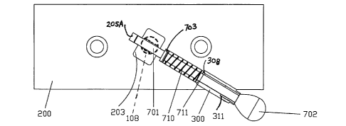
developing systems or
machines have been developed utilizing, for example, systems which incorporate
a selectable
weight stack. By design, the known equipment allows a user to, within the
module, increase
weight as the available resistance is incrementally selectable. These systems
often promise faster
and better results for exercisers. Although history shows the ingenuity of the
advancement of
mechanical and/or biomechanics may benefit muscle growth, little or no effort
has been made to
simplify, make safer and contemporize the selectorized weight stack for over
four decades.
[0003] Conventional weight stacks are, typically, multiple layers of metal-
based plates which
collectively amass an aggregate amount of weight. Generally, a weight stack
includes a variety
of rectangular weight plates, typically one inch thick and about 10 by 4
inches. Each
conventional plate known in the art incorporates four boreholes therein. Three
throughbores pass
vertically through the thickness of the plate from the top surface to the
bottom surface. The
CA 02739817 2011-04-06
WO 2010/042086 PCT/US2008/011538
2
fourth bore passes horizontally from the front face within the width of the
plate (between the top
and bottom surfaces) and intersects the middle one of the three bore holes.
[0004] Two throughbores engage or receive a pair of spaced-apart guide rods
and cause the plate
to track vertically thereon. The middle throughbore accommodates a center
post. The center post
has multiple diametric throughbores therein to act as a recipient for a
separate selector pin which
passes through the fourth throughbore. Thus, each plate may be independently
and selectively
engaged as part of the weight stack by manually inserting the selector pin
which is, typically,
slightly longer than the width of a plate and has a knob of sorts on one end
so that a user may
better manipulate the selector pin. The pin is inserted through the fourth
throughbore in the plate
and a throughbore in the center post to lock the weight plate to the center
post which is then
moved when the apparatus is operated.
[0005] Although traditional weight stacks, such as those described above, have
succeeded in
carrying out the intended purpose, there are many areas for substantial
improvement.
[0006] One key problem often associated with traditional weight stacks is that
the selector pin is
removable and is often misplaced, stolen or damaged whereupon it is replaced
with a
functionally and/or structurally inadequately sized pin. This inappropriate
replacement
historically has caused bodily injury due to the violation of the inherent
design of the apparatus.
[0007] The removable pin also permits the user to easily modify the operation
of the apparatus
outside the manufacturer's design criteria for the plates and/or weight stack.
CA 02739817 2011-04-06
WO 2010/042086 PCT/US2008/011538
3
[0008] Additionally, there is a level of dexterity and hand-to-eye
coordination required to effect
the insertion of the selector pin in the horizontal throughbore of the weight
and the center post
which further limits the true and effective result.
[0009] Therefore, the need exists for a mare easily manufactured weight plate
having a
construction that minimizes confusion on the part of the user, possibility for
misuse or failure,
and the possibility of injury to the user, yet retains the convenient exchange
of weight without
danger to the user. The weight plate of the present invention satisfies this
need.
[0010] Reference is made to my United States patent entitled WEIGHT PLATE WITH
EXTERNALLY ACTUATED INTERNAL LOCKING DEVICE granted 20 February 2007
under Patent No. 7,179,208.
SUMMARY OF THE INVENTION
[0011] The weight plate of the present invention provides a convenient,
integrally assembled
apparatus for enabling an internal pin to selectively engage or disengage an
associated apparatus.
[0012] The weight plate includes a plate body with a central and two outwardly
throughbores
which pass vertically therethrough. The body additionally has an internal
horizontal bore which
intersects the central vertical throughbore within the thickness of the plate
body. A selector pin is
movably mounted within the internal horizontal bore to selectively engage the
plate body to a
center post of the associated apparatus which center post passes through the
central throughbore.
A positioning sleeve is mounted in the internal bore in the plate to
selectively position the
selector pin within the internal bore. A spring engages the selector pin to
provide a positioning
force to the selector pin within the positioning sleeve.
CA 02739817 2011-04-06
WO 2010/042086 PCT/US2008/011538
4
BRIEF DESCRIPTION OF THE DRAWINGS
[0013] Figure 1 is a partially exploded, perspective view of a weight plate
assembly known in
the prior art.
[0014] Figure 2 is a cutaway view of the weight plate apparatus of the instant
invention.
[0015] Figure 3 is a plan view of one side surface of the weight plate
apparatus shown in Figure
2.
[0016] Figure 4 is an enlarged side view of the positioning sleeve used in the
weight plate
apparatus of the instant invention.
[0017] Figure 5 is an end view of the positioning sleeve shown in Figure 4.
[0018] Figure 6 is a cross-sectional view of the positioning sleeve shown in
Figure 4.
[0019] Figure 7 is a plan view of the locking pin mechanism of the weight
plate apparatus of the
instant invention.
[0020] Figure 8 is a cutaway view of the weight plate apparatus in the engaged
position.
[0021] Figure 9 is a cutaway view of the weight plate apparatus in the
disengaged position.
DESCRIPTION OF A PREFERRED EMBODIMENT
CA 02739817 2011-04-06
WO 2010/042086 PCT/US2008/011538
[0022] Referring now to Figure 1, there is shown a conventional weight plate
100 which is
known in the art. Typically, multiple layers of metal-based plates are used to
collectively amass
an aggregate gross weight in a weight machine. Generally, a weight plate 100
comprises a
rectangular body, typically about one inch thick and about 10 inches by 4
inches. A conventional
weight plate 100 incorporates three vertical throughbores 101, 102 and 103
which pass through
the thickness of the plate from the top surface to the bottom surface. A
fourth throughbore 105
passes horizontally through the width of the plate, i.e., from front to back
between the top and
bottom surfaces. Throughbore 105 intersects the middle throughbore 103 and
passes
therethrough into the plate on the other side of throughbore 103.
[0023] In a typical utilization, throughbores 101 and 102 engage a pair of
spaced apart guide
rods 106 and 107 (shown in dashed outline). This arrangement permits the plate
100 to track
vertically on the guide rods.
[0024] The middle throughbore 103 accommodates a center post 108 also shown in
dashed
outline. The center post 108 has multiple diametric throughbores 109 to act as
a recipient for a
selector pin 110 which passes through throughbore 105. Each plate 100 may be
independently
selected by way of manually inserting the selector pin 110 which is,
typically, slightly longer
than the front-to-back width of any one plate and has a suitable knob 11 OA at
one end so that a
user may better manipulate the pin. The pin is manually inserted through
throughbore 105 and a
throughbore 109 in the center post 108 (after moving the weights vertically up
or down) to select
a desired weight plate.
[0025] Although conventional weight stacks, such as those described above,
have succeeded in
carrying out the intended purpose, there are many areas for substantial
improvement. For
CA 02739817 2011-04-06
WO 2010/042086 PCT/US2008/011538
6
example, the selector pin 110 is frequently misplaced and replaced with a
functionally and/or
structurally inadequate sized pin. This inappropriate replacement has,
historically, let to bodily
injury due to the inherent design flaw which permits the freedom of user to
openly modify the
use of the system outside the manufacturer's intent and/or the plate's (weight
stack) design.
[0026] Additionally, there is a level of dexterity and hand-to-eye
coordination required to effect
this "engagement" of the selector pin 110 in the throughbore 105 of the weight
plate 100 which
further limits usage of the weight system or apparatus.
[0027] Referring now to Figure 2, there is shown a cutaway view of the
selector weight plate ,
200 of the instant invention. The selector weight plate 200 has the
traditional rectangular
configuration and is formed from a rigid material, such as iron, steel,
urethane, rubber, plastic or
a composite material. In order to provide a range of plates having varying
weight, the
dimensional characteristics of the plate often vary. As an example, a ten-
pound weight plate may
have a dimension of 10 inches long by 4 inches wide by 1 inch thick. These
dimensions are
illustrative only and are not limitative. The shape and size of the plate are
subject to design
preference.
[0028] The plate 200 is, typically, similar to the prior art weight plate
formed with a middle
throughbore 203 so as to accept a pin receiving adjustment bar (see center
post 108 in Figure 1)
and two adjacent throughbores 201 and 202 which include low friction type
bearings 206 and
207, respectively. Throughbores 201 and 202 receive the vertical guide bars
(see bars 106 and
107 in Figure 1) which stabilize the selected plate.
CA 02739817 2011-04-06
WO 2010/042086 PCT/US2008/011538
7
[0029] The plate 200 is further formed with cavity 205 which permits the
insertion and
movement of the locking pin 701 (see Figures 7-9) through the throughbore 203
and the center
post 108 into bore end cavity 205A when actuated by the external handle 702.
The outer end of
cavity 205 is adapted to receive sleeve 300 (see Figure 4) which is inserted
into the plate 200.
Cavity 205 includes an internal threaded portion 205B which is adapted to
threadedly receive
and engage the interior end 305 of sleeve 300.
[0030] Referring now to Figure 3, there is shown a plan view of one side
surface of the weight
plate 200 of the instant invention. The plate 200 is formed with internal
cavity 205 at the front
edge surface which permits the insertion of the pin assembly 700 (see Figure
7). The cavity 205
communicates with throughbore 203 which houses support post 108. The threaded
portion 205B
at the surface of cavity 205 is shown. The cavity 205 is properly sized to
permit movement of the
pin 701 when actuated at the external end thereof. It is understood that the
cavity 205 may be
formed in any side surface of the plate 300 as may be desired.
[0031] Figure 4 is a side view of the sleeve 300 which is generally
cylindrical in shape with a
threaded portion 305 adjacent end 308 of the cylindrical body. The threaded
portion 305 is
provided to engage the threaded interior section 205B of cavity 205 in the
weight plate (see
Figures 2 and 3). While not limited thereto, the sleeve 300 is, typically,
fabricated of a high
strength plastic material.
[0032] A generally hexagonal shaped end 306 is formed at the opposite end of
sleeve 300. The
"hex" shape is generally useful for tightening and securing the threaded
engagement of sleeve
300 within the oavity 205 in plate 200 by means of a wrench or the like.
CA 02739817 2011-04-06
WO 2010/042086 PCT/US2008/011538
8
[0033] Figure 5 is a view of the sleeve 300 from the right end thereof (as
shown in Figure 4).
The "hex nut" end 306 is shown. In addition, the end view shows the slot 310
formed in the inner
wall 300A of the cylindrical body of sleeve 300. The slot 310 selectively
permits sliding travel of
retaining pin 711 on engagement pin 701 therethrough (see Figure 3).
[0034] Figure 6 is a cutaway view of the sleeve 300 which shows the threaded
end 305 thereof
and the end surface 308. The slot 310 in the inner wall 300A is shown along
with the
discontinuous ledge 311 which is formed at the outer end of the inner wall
300A.
[0035] Figure 7 is a plan view of the locking pin mechanism 700. The mechanism
includes a pin
701 which is, in effect, a rod or shaft formed of a suitably strong material
such as but not
limitative to steel or the like. The pin 701 is attached to (or integrally
formed with) a suitable
handle such as knob 702. In a preferred embodiment, the pin 701 is formed of
metal and
threadedly attached to knob 702 which is manufactured of wood, plastic or the
like.
[0036] The shaft of pin 701 includes a retainer ring 703 which is swaged, or
otherwise fastened,
to the pin 701. The retainer ring 703 is properly sized to pass through the
main body of cavity
205 but not the outer portion thereof
[0037] In addition, a coil spring 710 encircles the shaft of pin 701 and is
engaged by (or seated
on) the retainer ring 703.
[0038] A retaining pin 711 is formed or otherwise provided at the shaft of pin
701. The retaining
pin 711, which may be swaged to the shaft 701, extends radially therefrom. The
retaining pin is
CA 02739817 2011-04-06
WO 2010/042086 PCT/US2008/011538
9
sized to selectively pass through slot 310 (see Figures 5 and 6) and to
selectively engage the
discontinuous ledge 311 in the sleeve 300.
[0039] The weight plate 200 of the instant invention is assembled by forming
the plate 200 as
shown. The spring 710 is passed over the end of the shaft of pin 701 and into
engagement with
the retaining ring 703 before the knob 702 is attached to the outer end of the
pin.
[0040] Likewise, the shaft of the pin 701 is passed through the sleeve 300
from the threaded end
365. The knob 702 is then attached to the shaft of pin 701 thus capturing the
spring 710 on the
shaft of the pin 701 between the knob 702 and the bottom end 308 of sleeve
300.
[0041] The sleeve 300 (with pin 701 therein) is then inserted into cavity 205
through the outer
opening in the side wall shown best in Figure 3. The threaded end 305 of
sleeve 300 is then
threadedly engaged with the threaded portion 205A of cavity 205. The sleeve
300 is snugly
secured by means of a wrench or the like applied at the hex end 306 of the
sleeve.
[0042] Figure 8 shows a cutaway view of the weight plate 200 in the unlocked
(or disengaged)
position relative to the support post 108. That is, the pin 701 is,
effectively, stored in the cavity
205.
[0043] To store the pin 701 (or to release the pin 701 from engagement with
the support post
108), the knob 702 is rotated until the retaining pin 711 is aligned with slot
310 in sleeve 300.
The knob 702 is pulled outwardly along with pin 701 which passes through the
sleeve 300
thereby compressing spring 710 between ring 703 and the inner end 308 of
sleeve 300. When the
pin 701 (with the retaining pin 711) has passed through the central aperture
in the sleeve, the pin
CA 02739817 2014-06-17
701 is rotated so that the retaining pin 711 is out of alignment with slot
310. The retaining pin
711 is locked against the inner ledge 311 at the outer end of sleeve 300. At
this point the pin 701
is disengaged from post 108 and the weight plate 200 can be added to or
removed therefrom.
[0044] Figure 9 shows a cutaway view of the weight plate 200 with the pin 701
in the locked
position relative to the support post 108. In order to lock the weight plate
200 to the center post
108, the knob 702 (and attached pin 701) is rotated thereby aligning the
retaining pin 711 with
the slot 310 in sleeve 300 whereupon the spring 710, compressed between sleeve
end 308 and
retainer ring 703, is able to force the pin 701 inwardly into bore end 205A
via the diametric
throughbore in support post 108 within throughbore 203. The spring 710
maintains the pin 701 in
the locked position and engages the plate to the support port until the pin
701 is released as
discussed relative to Figure 8.
[0045] Thus, it is noted that the locking mechanism remains with the weight
plate but is readily
accessed outside the dimensions of the plate for safety. Those skilled in the
art will appreciate
the many benefits and advantages afforded the present invention. Of
significant importance is the
ability to easily and safely select weight with a single finger while
maintaining the advantage of
providing an integrally formed and uniform system to reduce cost and liability
exposure to the
consumer.
[0046] While the invention has been particularly shown and described with
reference to the
preferred embodiments thereof, it will be understood by those skilled in the
art that various
changes in form and detail may be made therein without departing from the
scope of the
invention.
CA 02739817 2011-04-06
WO 2010/042086 PCT/US2008/011538
11
[0047] Thus, there is shown and described a unique design and concept of a
weight plate with
externally actuated spring loaded internal locking device. While this
description is directed to
particular embodiments, it is understood that those skilled in the art may
conceive modifications
and/or variations to the specific embodiments, shown and described herein. Any
such
modifications or variations which within the purview of this description are
intended to be
included therein as well. It is understood that the description herein is
intended to be illustrative
only and is not intended to be limitative. Rather, the scope of the invention
described herein is
limited only by the claims appended hereto.