Language selection

Search

Patent 2739855 Summary

Third-party information liability

Some of the information on this Web page has been provided by external sources. The Government of Canada is not responsible for the accuracy, reliability or currency of the information supplied by external sources. Users wishing to rely upon this information should consult directly with the source of the information. Content provided by external sources is not subject to official languages, privacy and accessibility requirements.

Claims and Abstract availability

Any discrepancies in the text and image of the Claims and Abstract are due to differing posting times. Text of the Claims and Abstract are posted:

  • At the time the application is open to public inspection;
  • At the time of issue of the patent (grant).
(12) Patent: (11) CA 2739855
(54) English Title: ALARM MARK STRUCTURE OF A MICRO-DIFFERENTIAL PRESSURE GAUGE
(54) French Title: STRUCTURE DU CRAN D'ALERTE D'UN MICRO-MANOMETRE DIFFERENTIEL
Status: Deemed expired
Bibliographic Data
(51) International Patent Classification (IPC):
  • G01L 13/00 (2006.01)
  • G01L 19/12 (2006.01)
(72) Inventors :
  • CHEN, LI-CHEN (Taiwan, Province of China)
(73) Owners :
  • HWA CHI TECHNOLOGY CO., LTD. (Taiwan, Province of China)
(71) Applicants :
  • CHEN, LI-CHEN (Taiwan, Province of China)
(74) Agent: ADE & COMPANY INC.
(74) Associate agent:
(45) Issued: 2015-05-12
(22) Filed Date: 2011-05-16
(41) Open to Public Inspection: 2011-11-20
Examination requested: 2011-05-16
Availability of licence: N/A
(25) Language of filing: English

Patent Cooperation Treaty (PCT): No

(30) Application Priority Data:
Application No. Country/Territory Date
TW099209463 Taiwan, Province of China 2010-05-20

Abstracts

English Abstract

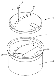
An alarm mark structure of a micro-differential pressure gauge includes a transparent casing. The transparent casing has at least one recess thereon. The recess is located corresponding to the range of movement of a pointer or a scale plate. At least one mark member is provided on the transparent casing. The mark member has an engaging portion. The engaging portion is inserted in the recess, such that the mark member is coupled on the transparent casing. The user can place the mark member on the recess corresponding to the numerical value on the scale plate as desired to know whether the pointer is located within a safe area.


French Abstract

Une structure de marquage dalerte dun micromanomètre différentiel comprend un boîtier transparent. Le boîtier transparent possède au moins un renfoncement. Le renfoncement est situé en correspondance à la plage de mouvement dun pointeur ou dune plaque graduée. Au moins un élément de marquage est proposé sur le boîtier transparent. Lélément de marquage possède une partie de mise en prise. La partie de mise en prise est insérée dans le renfoncement, de sorte que lélément de marquage est couplé sur le boîtier transparent. Lutilisateur peut placer lélément de marquage sur le renfoncement qui correspond à la valeur numérique sur la plaque graduée comme souhaité pour savoir si le pointeur est situé dans une zone sûre.

Claims

Note: Claims are shown in the official language in which they were submitted.


WHAT IS CLAIMED IS:
1. An alarm mark structure of a micro-differential pressure gauge, comprising:
a gauge base comprising a pointer, an axle and a scale plate therein, the
pointer
moving through the axle to display a numerical value on the scale plate;
a transparent casing coupled on the gauge base, the transparent casing having
at least one recess thereon, the recess being located corresponding to the
range of
movement of the pointer; and
at least one mark member, the mark member having an engaging portion, the
engaging portion being inserted in the recess,
wherein the recess is a concave hole on the transparent casing, not a through
hole.
2. The alarm mark structure of a micro-differential pressure gauge as claimed
in
claim 1, wherein the recess and the engaging portion are tightly engaged.
3. The alarm mark structure of a micro-differential pressure gauge as claimed
in
claim 1, wherein the mark member has a pointed end.
4. The alarm mark structure of a micro-differential pressure gauge as claimed
in
claim 1, wherein the mark member is colored.
4

Description

Note: Descriptions are shown in the official language in which they were submitted.


CA 02739855 2014-01-30
ALARM MARK STRUCTURE OF A MICRO-DIFFERENTIAL PRESSURE GAUGE
BACKGROUND OF THE INVENTION
1. Field of the Invention
The present invention relates to an alarm mark structure of a micro-
differential
pressure gauge, and more particularly, to a pointer gauge structure having a
mark
member which is coupled to a recess of a transparent casing.
2. Description of the Prior Art
A conventional gauge, such as a micro-differential pressure gauge or a
pressure
gauge, includes a pointer therein. The pointer is rotated according to the
pressure.
In conjunction with a numeral scale plate in the gauge, the user can read the
value.
In general, the gauge is set with a security value. For the user to know
whether or
not the pointer is in the range of safety, the gauge is provided with a safety
mark.
The conventional mark is secured on an outer edge of the gauge. When the gauge

has to be installed in an embedded way, such as in a hole of a flat board of
an
apparatus, the mark cannot be attached to the gauge because the
circumferential
edge of the gauge is tightly against the flat board. Accordingly, the inventor
of the
present invention has devoted himself based on his many years of practical
experiences to solve this problem.
SUMMARY OF THE INVENTION
One aspect of the present invention provides an alarm mark structure of a
micro-differential pressure gauge. A mark member is disposed on a transparent
casing, which doesn't exceed the circumference of the gauge, such that the
mark
member can be easily coupled to the gauge which is installed in an embedded
way.
In order to achieve this, an alarm mark structure of a micro-differential
pressure
gauge includes a transparent casing. The transparent casing has at least one
recess thereon. The recess is located corresponding to the range of movement
of a
pointer or a scale plate. At least one mark member is provided on the
transparent
casing. The mark member has an engaging portion. The engaging portion is
inserted in the recess, such that the mark member is coupled on the
transparent
casing. The user can place the mark member on the recess corresponding to the
numerical value on the scale plate as desired to know whether the pointer is
located

CA 02739855 2014-01-30
within a safe area.
Preferably, the recess is a concave hole on the transparent casing, not a
through
hole.
Preferably, the recess and the engaging portion are tightly engaged.
Preferably, the mark member has a pointed end for the user to see the pointer
easily.
Preferably, the mark member is colored such as red, to provide an alarm
effect.
According to an aspect of the invention, there is provided an alarm mark
structure
of a micro-differential pressure gauge, comprising; a gauge base comprising a
pointer,
an axle and a scale plate therein, the pointer moving through the axle to
display a
numerical value on the scale plate; a transparent casing coupled on the gauge
base,
the transparent casing having at least one recess thereon, the recess being
located
corresponding to the range of movement of the pointer, and at least one mark
member, the mark member having an engaging portion, the engaging portion being
inserted in the recess, wherein the recess is a concave hole on the
transparent casing,
not a through hole.
BRIEF DESCRIPTION OF THE DRAWINGS
Fig. I is an exploded view according to a preferred embodiment of the present
invention;
Fig. 2 is a perspective view according to the preferred embodiment of the
present
invention;
Fig. 3 is a top view according to the preferred embodiment of the present
invention;
and
Fig. 4 is another top view according to the preferred embodiment of the
present
invention to show that the position of the mark member is changed.
DETAILED DESCRIPTION OF THE PREFERRED EMBODIMENTS
Embodiments of the present invention will now be described, by way of example
only, with reference to the accompanying drawings.
As shown in Fig. I and Fig. 2, an alarm mark structure of a micro-differential
pressure gauge according to a preferred embodiment of the present invention
2

CA 02739855 2014-01-30
comprises a gauge base 1, a transparent casing 3, and a mark member 4.
The gauge base 1 is incorporated with other parts to become a pointer gauge
which may be a pressure gauge or a micro-differential pressure gauge. The
gauge
base 1 comprises a pointer 21, an axle 20 and a scale plate 22 therein. The
pointer
21 can be moved through the axle 20 in accordance with the inside pressure to
display the numerical value on the scale plate 22.
The transparent casing 3 is coupled on the gauge base 1. The transparent
casing 3 has at least one recess 31 thereon. The recess 31 is located
corresponding
to the range of movement of the pointer 21 or the scale plate 22. The recess
31 is a
concave hole on the transparent casing 3, not a through hole. The mark member
4
has an engaging portion 41. The engaging portion 41 is inserted in the recess
31,
such that the mark member 4 is coupled to the transparent housing 3.
The recess 31 and the engaging portion 41 are tightly engaged.
Preferably, the mark member 4 has a pointed end. The mark member 4 is
colored, such as red, to provide an alarm effect.
When in use, as shown in Fig. 3, two mark members 4 are engaged in the desired

recesses 3110 indicate a safe area and an alarm threshold value. If the
pointer 21
passes any mark member 4, the observer will know easily and handle the crisis
immediately.
Referring to Fig. 4, the transparent casing 3 has a plurality of recesses 31.
The
user can change the position of the mark member 4, so that the alarm value is
changed as desired.
The mark member 4 is disposed within the gauge surface. Even if the gauge is
installed in an embedded way, the mark member 4 of the present invention is
disposed externally and can be seen with ease.
The scope of the claims should not be limited by the preferred embodiments set

forth in the examples, but should be given the broadest interpretation
consistent with
the description as a whole.
3

Representative Drawing
A single figure which represents the drawing illustrating the invention.
Administrative Status

For a clearer understanding of the status of the application/patent presented on this page, the site Disclaimer , as well as the definitions for Patent , Administrative Status , Maintenance Fee  and Payment History  should be consulted.

Administrative Status

Title Date
Forecasted Issue Date 2015-05-12
(22) Filed 2011-05-16
Examination Requested 2011-05-16
(41) Open to Public Inspection 2011-11-20
(45) Issued 2015-05-12
Deemed Expired 2017-05-16

Abandonment History

There is no abandonment history.

Payment History

Fee Type Anniversary Year Due Date Amount Paid Paid Date
Request for Examination $400.00 2011-05-16
Application Fee $200.00 2011-05-16
Maintenance Fee - Application - New Act 2 2013-05-16 $50.00 2013-05-09
Maintenance Fee - Application - New Act 3 2014-05-16 $50.00 2014-04-09
Registration of a document - section 124 $100.00 2015-02-12
Final Fee $150.00 2015-02-12
Maintenance Fee - Application - New Act 4 2015-05-19 $50.00 2015-05-05
Owners on Record

Note: Records showing the ownership history in alphabetical order.

Current Owners on Record
HWA CHI TECHNOLOGY CO., LTD.
Past Owners on Record
CHEN, LI-CHEN
Past Owners that do not appear in the "Owners on Record" listing will appear in other documentation within the application.
Documents

To view selected files, please enter reCAPTCHA code :


To view images, click a link in the Document Description column. To download the documents, select one or more checkboxes in the first column and then click the "Download Selected in PDF format (Zip Archive)" or the "Download Selected as Single PDF" button.

List of published and non-published patent-specific documents on the CPD .

If you have any difficulty accessing content, you can call the Client Service Centre at 1-866-997-1936 or send them an e-mail at CIPO Client Service Centre.


Document
Description 
Date
(yyyy-mm-dd) 
Number of pages   Size of Image (KB) 
Abstract 2011-05-16 1 16
Description 2011-05-16 3 127
Claims 2011-05-16 1 27
Drawings 2011-05-16 4 48
Representative Drawing 2011-10-25 1 7
Cover Page 2011-11-03 1 37
Description 2014-01-30 3 135
Claims 2014-01-30 1 25
Cover Page 2015-04-22 2 40
Assignment 2011-05-16 3 95
Correspondence 2011-05-26 1 40
Correspondence 2011-05-26 1 74
Prosecution-Amendment 2013-08-07 3 117
Prosecution-Amendment 2014-01-30 7 236
Correspondence 2015-02-12 2 57
Assignment 2015-02-12 3 104