Note: Descriptions are shown in the official language in which they were submitted.
CA 02739861 2011-04-07
WO 2009/046994
PCT/EP2008/008586
IMPLANTABLE TISSUE CONNECTOR
Background of the invention
[0001] The present invention relates to an implantable tissue connector that
is
specifically adapted to be connected to a tubular part of living tissue within
a
patient's body, such as to the end of the human's large bowel when an
artificial
exit to the large bowel is to be provided. However, the implantable tissue
connector of the present invention is not limited to such application and can
be
used in connection with many other kinds of tubular living tissue, as will be
described in more detail below.
[0002] Connecting the end of the human's large bowel to an artificial exit,
such as
to a fecal excrements collecting container, or connecting a shortened large
bowel
to the patient's natural intestinal exit has always proven difficult and often
unreliable. Leakage can occur where the connection is not tight over the
lifetime.
Blood circulation can be prohibited in the end area of the bowel tissue, which
can
negatively affect the muscle functions and peristaltic movement of the bowel
and
which can even lead to starvation of the respective portion of the bowel.
Furthermore, the peristaltic movement of the bowel will continuously act upon
the
connection and, thus, the connection can fail over time.
Summary of the invention
[0003] It is therefore an object of the present invention to provide an
implantable
tissue connector for connecting tubular living tissue in a patient's body,
which
connection should be reliable over time and not severely harm the living
tissue.
[0004] It is a further object to propose different uses for such tissue
connector as
well as methods for implanting the tissue connector in a patient's body.
CA 02739861 2016-01-13
. =
54538-1
la
[0004a] According to one aspect of the present invention, there is
provided an
implantable tissue connector adapted so as to be connectable to a cross-
sectional
open end portion of a tubular part of living tissue within a patient's body,
comprising a
conduit having at least a first and a second end and further having an outer
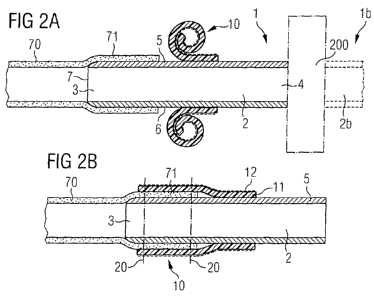
surface,
and at least one flexible sleeve adapted to axially extend and closely fit
around at
least part of said outer surface of the conduit, said flexible sleeve
comprising a
porous ingrowth layer allowing ingrowth of living tissue and a support layer
for
supporting said porous ingrowth layer, said flexible sleeve being (a) mounted
on said
outer surface of said conduit either folded or rolled upon itself so that it
can be
unfolded or unrolled so that at least part of the living tissue extending over
the
conduit's outer surface can be located intermediate the flexible sleeve and
the outer
surface of the conduit with the porous ingrowth layer contacting the living
tissue,
when implanted in a patient's body, or (b) mounted on said outer surface so as
to be
foldable upon itself so that at least part of the living tissue can be located
intermediate the folded sleeve or intermediate the conduit's outer surface and
the
flexible sleeve with the porous ingrowth layer contacting the living tissue,
when
implanted in a patient's body.
CA 02739861 2015-03-26
= 54538-1
2
[0005] Accordingly, the implantable tissue connector of the present invention
comprises a conduit with at least a first and a second end and further having
an
outer surface on which may be mounted at least one flexible sleeve axially
extending around at least part of said conduit. According to a first
embodiment,
the flexible sleeve is initially mounted on said outer surface either folded
or rolled
upon itself. According to a second embodiment, the flexible sleeve is
initially
mounted on said outer surface so as to be foldable upon itself.
[0006] The first end of the conduit of the tissue connector is connected to a
tubular part of living tissue by inserting the first end of the conduit into
the tubular
part of living tissue. Where, according to the first embodiment, the flexible
sleeve
is mounted on the outer surface of the conduit folded or rolled upon itself,
the
flexible sleeve is unfolded or unrolled such that at least part of the living
tissue
extending over the conduit's outer surface is located intermediate the sleeve
and
the outer surface of the conduit. Where, according to the second embodiment,
the
flexible sleeve is mounted on the outer surface of the conduit so as to be
foldable
upon itself, the flexible sleeve is folded upon itself such that at least part
of the
living tissue is located intermediate the folded sleeve or intermediate the
conduit's
outer surface and the sleeve.
[0007] Either way, the tubular tissue is located somewhere between the conduit
and the flexible sleeve and can be held in that position in various manners
that will
be described in the following and that can be applied individually as well as
in
combination.
[0008] The advantages achieved with the tissue connector according to the
present invention comprise a good sealing of the living tissue between the
conduit
and the flexible sleeve as well as good protection of the living tissue by the
flexible
CA 02739861 2011-04-07
WO 2009/046994
PCT/EP2008/008586
3
sleeve. This way, the connection can be made reliable over time while also
protecting the tissue against harm.
[0009] Where the flexible sleeve overlaps with the living tissue that has been
drawn over the first end of the conduit, it is desirable that the flexible
sleeve will
exert radial pressure upon the tissue. In applications where there is no
movement
to be expected, this may be sufficient to hold the tissue connector in place.
In
other instances, where the movement of the tissue material is to be expected,
such as when used as a bowel connector, the radial pressure will assist in
holding
the components in place until they are otherwise fixed against one another. In
any
case, it is preferable to design the flexible sleeve such that the radial
pressure is
minimal so as not to prohibit the blood circulation in the living tissue.
[0010] Furthermore, the conduit should be designed such that it is less
flexible
than the flexible sleeve at least in a radial direction so as to provide
support to the
sleeve against radial forces, in particular against the sleeve's
aforementioned
radial pressure. This way, the open internal cross section of the conduit will
not be
affected by the radial forces caused by the flexible sleeve.
[0011] Another particularly preferred way of reliably connecting the living
tissue to
the tissue connector involves a flexible sleeve that comprises a porous
ingrowth
layer allowing ingrowth of living tissue. This will not only strengthen any
connection
between the tissue connector and the tissue but will also serve to further
seal the
connection against any leakage.
[0012] The ingrowth layer should be made from a material that stimulates
tissue
ingrowth. Preferably, the ingrowth layer has a netlike structure that can be
penetrated by ingrowing tissue, thereby creating a durable connection between
the
living tissue and the flexible sleeve. Of course, the ingrowth layer should be
made
from a biocompatible material, such as Dacron .
[0013] Another way of reliably fixing the living tissue to the tissue
connector
consists in suturing the flexible sleeve to the living tissue. Alternatively,
the
suturing may be performed through the flexible sleeve and an outer wall of the
conduit including an interposed portion of the living tissue. Thereby, the
tissue is
CA 02739861 2011-04-07
WO 2009/046994
PCT/EP2008/008586
4
fixed to both the flexible sleeve and the conduit. Leakage through needle
penetrations caused by the suturing, if any, will automatically close over
time by
overgrowing tissue material.
[0014] It is also possible to perform the suturing through a portion of the
living
tissue and the outer wall of the conduit before the flexible sleeve is placed
over the
living tissue. This eliminates any problems of leakage through the penetration
holes caused by the suturing as the sleeve will cover and seal such
penetration
holes.
[0015] Preferably, the thread used for suturing is made from a material that
is
absorbable by the patient's body. Typically, the thread will be absorbed by
the
body within about 6 weeks. At that time, however, the tissue ingrowth will be
sufficiently advanced to compensate for the loss of strength that was
initially
provided by the thread.
[0016] Instead or in addition to suturing the flexible sleeve to the conduit
by
means of a preferably absorbable thread, the sleeve may be fixedly connected
to
the conduit along an axially extending portion of the sleeve in any other
appropriate way. For instance, the conduit and the sleeve may be bonded along
at
least part of said axially extending portion of the sleeve. A primer may be
applied
on the conduit's outer surface and/or the flexible sleeve to enhance bonding
characteristics.
[0017] The flexible sleeve may comprise a multi-layer material. This is
particularly
advantageous where the flexible sleeve comprises the aforementioned porous
ingrowth layer. For instance, the porous ingrowth layer might itself not be
sufficiently stable to be safely handled and pulled over the tubular tissue
and/or
the porous ingrowth layer might not be able to exert the radial pressure onto
the
tissue. In either of these cases, it is advantageous to provide the flexible
sleeve
with a support layer for supporting the porous ingrowth layer.
[0018] The support layer may be made e.g. from polyurethane or from expanded
polytetrafluoroethylene (ePTFE). ePTFE is particularly preferred as it can be
designed with pores sufficiently large in size so as to allow for the
necessary
CA 02739861 2011-04-07
WO 2009/046994
PCT/EP2008/008586
exchange of particles and/or elements between the underlying tissue and the
surrounding area of the patient's body. Furthermore, the support layer may
give
better protection to the tissue than the ingrowth layer.
[0019] It is preferable when after implantation the support layer forms an
outer
layer of the flexible sleeve or, at least, that the ingrowth layer will be
located radial
inward from the support layer. Thus, where the flexible sleeve is mounted on
the
outer surface of the conduit so as to be foldable up on itself, the ingrowth
layer will
be located between portions of the support layer when the sleeve is folded
upon
itself. Alternatively, where the flexible sleeve is mounted on the outer
surface of
the conduit folded or rolled upon itself, the ingrowth layer will be located
radial
inward from the support layer when the sleeve is unfolded or unrolled.
[0020] In the regards of materials, both the conduit and the flexible sleeve
should
preferably be made from biocompatible material. As far as the sleeve is
concerned, it preferably comprises polymers, such as polytetrafluoroethylene
(PTFE), ePTFE, silicone and/or polyurethane.
[0021] As far as the conduit is concerned, the same and other biocompatible
polymer materials can be used, including e.g. polyetheretherketone (PEEK).
However, other materials, such as ceramics and metals, in particular titanium
and
stainless steel, can be used as well and are preferable for their strength.
[0022] The conduit can be substantially longer than the particular portion of
the
conduit to which the tubular tissue is connected. In that case, it is
preferable that
the flexible sleeve is located proximately to the respective end of the
conduit so
that the part of the tissue drawn over the conduit is not excessively large.
The
larger the overlapping part of the tissue is, the larger may become problems
of
blood circulation within that part of the tissue.
[0023] The tissue connector may be intended for connecting with one another
two different ends of tubular living tissue. In this case, the conduit may
have one
flexible sleeve at each of the conduit's first and second ends. Again, the
flexible
sleeves are preferably located proximately to said first and second ends.
CA 02739861 2011-04-07
WO 2009/046994
PCT/EP2008/008586
6
[0024] In order to facilitate the step of inserting the end or ends of the
conduit
into the tubular living tissue, it is advantageous to taper the free end
portion of the
conduit's end or ends towards the edge of said free end portion. Alternatively
or in
addition, the free end portion may be provided with a rounded edge. The
rounded
edge will help to prevent any damage to the living tissue when the tissue is
pulled
over the free end of the conduit.
[0025] According to another particularly preferred embodiment of the
invention,
there are provided special elements for preventing the tubular tissue from
slipping
off of the conduit. Again, these means can be combined with any of the
aforementioned options of fixing the living tissue to the tissue connector.
[0026] More particularly, according to this preferred embodiment, the tissue
connector comprises at least one bulge extending outwardly from the conduit's
outer surface in a circumferential direction of the conduit about at least
part of the
conduit's circumference. Furthermore, at least one blocking ring is loosely
fitted
over the outer surface of the conduit with a clearance between the conduit's
outer
surface and the blocking ring for mounting living tissue within said
clearance. The
blocking ring has an inner cross sectional diameter which is smaller than or
substantially identical to an outer cross sectional diameter of the at least
one bulge
so as to prevent the blocking ring from slipping over the bulge when living
tissue is
mounted within the clearance.
[0027] When the tissue connector is implanted in a human being or animal, the
living tissue will be pulled over the conduit's outer surface including the
bulge.
Then the blocking ring will be advanced from the other side of the bulge over
the
living tissue towards the bulge such that at least part of the living tissue
is located
intermediate the conduit's outer surface and the blocking ring. This has the
effect
that, when the tissue tends to slip off of the conduit, it will carry the
blocking ring
towards and against the bulge. By this action, the living tissue will be
compressed
between the bulge and the blocking ring, thereby preventing any further
slippage.
This effect is self-enhancing with increasing slipping force. As the force
tends to
decrease again, the compression force will decrease accordingly so that blood
circulation within the living tissue will not be negatively affected longer
than
necessary.
CA 02739861 2011-04-07
WO 2009/046994
PCT/EP2008/008586
7
[0028] The size of the clearance in a radial direction depends upon the
intended
use of the tissue connector, i.e. upon the thickness of the tubular living
tissue to
which the tissue connector is connected. Accordingly, the size may be at
average
between 0.1 to 0.4 mm, 0.4 to 0.8 mm, 0.8 to 1.3 mm, 1.3 to 2 mm, 2 to 3 mm, 3
to 4 mm, 4 to 5 mm, over 5 mm. The clearance should be slightly smaller than
the
thickness of the living tissue so as not to severely affect blood circulation
within
the living tissue but nevertheless ensure sufficient frictional contact.
[0029] While the cross-sectional diameter of the blocking ring should
preferably
be smaller than the cross-sectional diameter of the bulge, it can in some
instances
be identical or even somewhat larger than this because the thickness of the
living
tissue, even in a compressed state, adds up to the cross-sectional diameter of
the
bulge so that alltogether the blocking ring is prevented from slipping over
the
bulge. Therefore, in case of particularly thick living tissue, the inner cross-
sectional
diameter of the blocking ring may be even somewhat larger than the outer cross-
sectional diameter of the bulge.
[0030] Of course, it is again preferable to make the blocking ring from a
biocompatible material, in particular those materials mentioned above that are
also
suitable for the conduit.
[0031] Where the tissue connector is intended to connect two different ends of
tubular living tissue material, it may have two of the aforementioned bulges,
preferably located proximately to the respective ends of the conduit, with
preferably at least two blocking rings located intermediate the two bulges. Of
course, more than one blocking ring and/or more than one bulge may be provided
for each end of the conduit.
[0032] A6 mentioned at the outset, the use of the tissue connector of the
present
invention is not limited to its application at the end of the human's large
bowel. It
can be advantageously used in many other applications.
[0033] For instance, the tissue connector may be fitted into a human's
esophagus. In this case, the conduit of the tissue connector should have an
inner
CA 02739861 2011-04-07
WO 2009/046994
PCT/EP2008/008586
8
diameter of between 2 and 3.5 cm to provide for a snug fit. The clearance
between
the conduit and the blocking ring should be in the range of 2.5 to 5 mm.
[0034] Where the tissue connector is connected to a human's trachea, the inner
diameter should be chosen between 1.5 and 2.5 cm, depending upon the position
where at the human's trachea it is to be connected, in order to provide for a
snug
fit. The clearance between the conduit and the blocking ring should be in the
range of 1 to 2 mm.
[0035] Where the tissue connector is fitted into a human stomach, the inner
diameter of the conduit can vary with enlarged boundaries. The clearance
between the conduit and the blocking ring should be in the range of 3.5 to 5
mm.
[0036] The tissue connector may also be fitted into a human's gall bladder or
its
connecting outlet channels. In that case, the conduit should have an inner
diameter of between 0.5 and 1.3 cm. The clearance between the conduit and the
blocking ring should be in the range of 0.5 to 1.5 mm.
[0037] In case that the tissue connector is fitted into a human's small bowel,
the
inner diameter of the conduit should be between 2 and 3 cm. The clearance
between the conduit and the blocking ring should be in the range of 3 to 4 mm.
[0038] In case of the human's large bowel, whose diameter is highly
stretchable,
the inner diameter of the conduit should be between 3 and 5.5 cm to provide
for a
snug fit. The clearance between the conduit and the blocking ring should be in
the
range of 2 to 3.5 mm.
[0039] The tissue connector may also be fitted into a human's urethra. In this
case, the conduit should have an inner diameter of between 0.4 and 0.8 cm. The
clearance between the conduit and the blocking ring should be in the range of
0.5
to 1.5 mm.
[0040] Also, the tissue connector may be fitted into an human's ureter, in
which
case the inner diameter of the conduit should be chosen between 0.4 and 0.7
cm.
CA 02739861 2011-04-07
WO 2009/046994
PCT/EP2008/008586
9
The clearance between the conduit and the blocking ring should be in the range
of
2 to 4 mm.
[0041] The tissue connector may also be connected to the kidney. In order to
snuggly fit it into a human's pelvic part of the kidney, the inner diameter of
the
conduit should be in the range of 1 and 5 cm, depending upon the position
where
at the human's pelvic it is to be connected. The clearance between the conduit
and the blocking ring should be in the range of 0.5 to 1.5 mm.
[0042] The tissue connector may also be fitted into a human's blood vessel. In
this case, the inner diameter of the conduit should be chosen approximately
similar to the inner diameter of the respective blood vessel. As an example,
the
inner diameter may be chosen between 0.1 and 0.5 cm in the case of
particularly
small blood vessels. The tissue connector may as well be connected to the
human's aorta or the heart's atrium or ventricle, in which case the inner
diameter
of the conduit is in the range of 2 to 3 cm. The clearance between the conduit
and
the blocking ring should be in the range of 1 to 2 mm.
[0043] The tissue connector may also be used as an intermediate piece to
replace a part of tubular living tissue and may as well be used to connect
different
types of tubular living tissue, such as where a biological transplant of a
third
party's body is to be connected to the organs of a patient.
[0044] The tissue connector may particularly be used and be adapted for
connecting it to at last one of an implantable reservoir, an implantable pump,
an
implantable motor, an implantable medical device and a biological transplant.
The
artificial items may even form a part of the tissue connector, either
integrally
formed therewith or separately connected thereto. The reservoir, pump, motor
and/or medical device may also be incorporated in the tissue connector between
the first and second ends of the conduit.
[0045] The biological transplant may be any transplant, such as a transplanted
heart to be connected by means of the tissue connector to the patient's aorta
and/or to other blood vessels (pulmonary arteria etc.).
CA 02739861 2011-04-07
WO 2009/046994
PCT/EP2008/008586
[0046] Instead of being artificial, the aforementioned reservoir may consist
of a
biological transplant, but it may as well be made from tissue material of the
patient
into whom the reservoir is to be implanted. For instance, the reservoir may be
a
fecal excrements collecting container, such as a urine bladder or an
intestine.
[0047] The reservoir may also be a reservoir for medical drugs for the
patient's
needs and is preferably adapted to be filled with at least one medical drug.
Such
medical drug reservoir may or may not be connected to a medical device, such
as
an implantable drug delivery device, which medical device may additionally
include
a pump for pumping the drug from the reservoir into the patient's body and
possibly a motor for the pump.
[0048] Any other implantable medical devices may also be connected to the
organs of the patient by means of the tissue connector, with or without a
pump,
motor and/or reservoir. Examples of these are an artificial heart, a penile
prothesis, an artificial urine bladder, an artificial urethra, an artificial
esophagus, an
artificial trachea and the like. Examples of biological transplants include a
urine
bladder, an intestine, a urethra, a ureter, a kidney, a bowel, a heart, an
esophagus, a trachea, a blood vessel and the like.
[0049] The tissue connector of the present invention can be implanted in a
human being or animal either in open surgery or by subcutaneous surgery. In
either case, the skin will have to be cut before free-dissecting an
appropriate
location within the patient's body adjacent to the tubular living tissue and,
after the
conduit of the tissue connector has been connected with one or both ends to
the
tubular tissue, at least the skin will have to be sutured at the end of the
surgery.
[0050] Where the tissue connector is implanted by subcutaneous surgery, the
steps of cutting the skin and free-dissecting the appropriate location within
the
patient's body comprise the steps of
- inserting a needle-like tube into the patient's body, such as the
patient's thorax
or abdomen,
- filling through said needle gas into the patient's body, i.e. into the
thorax cavity
or abdomen cavity,
CA 02739861 2011-04-07
WO 2009/046994
PCT/EP2008/008586
11
- cutting a key-hole,
- inserting at least one, preferably two, laparoscopic trocars through the
key-
hole towards said location,
- advancing one or more medical instruments and a camera through the at
least
one trocar towards said location, i.e. into the thorax or abdomen, and
- dissecting an area of the tubular part of living tissue with the aid of
the
dissecting tool.
- The tissue connector may be supplied to said location through the at
least one
trocar or through a separate incision.
[0051] The invention will now be described in more detail in context with some
preferred embodiments of the invention as shown in the accompanying drawings.
Brief description of the drawings
[0052] Figure 1 shows an examplary view of a patient with one tissue connector
connected to the patient's aorta and another tissue connector connected to the
end of the patient's large bowel.
[0053] Figures 2a and 2b show a cross-section of a first embodiment of the
tissue connector in the state of mounting and in the connected state.
[0054] Figures 3a and 3b show a cross-section of an alternative of the first
embodiment of the tissue connector in the state of mounting and in the
connected
state.
[0055] Figures 4a and 4b show a second embodiment of the tissue connector in
the state mounting and in the connected state.
[0056] Figure 5 shows an alternative for mounting living tissue on a free end
of
the tissue connector.
[0057] Figures 6a and 6b show a combination of an embodiment similar to the
one shown in Figures 2a and 2b with additional mounting means as shown in
figure 5.
CA 02739861 2011-04-07
WO 2009/046994
PCT/EP2008/008586
12
[0058] Figure 7 shows a specific embodiment of a tissue connector with two
ends
thereof connected to living tissue.
[0059] Figure 1 schematically shows a body 100 of a patient with a first
tissue
connector 1 connected to the end of the patient's large bowel 50 and a second
tissue connector la interconnecting two pieces of the patient's aorta 60. The
tissue connector 1 may either connect the large bowel 50 to the patient's anus
or
to an artificial anus which may include an excrements collecting container.
The
tissue connector la may include between its two ends a heart valve, a blood
pump, a drug delivery device or the like.
[0060] The tissue connectors 1 and la shown in Figure 1 represent only a few
of
many different possible locations and applications of the tissue connector
within
the human's or, alternatively, an animal's body. Further examples of possible
applications have already been outlined further above.
[0061] Figures 2a and 2b show a first embodiment of the tissue connector 1 in
the state of mounting the tissue connector to a tubular part of living tissue
70. The
tissue connector 1 comprises a conduit 2 with a first end 3 and a second end
4. In
Figure 2a, the first end 3 of the conduit 2 has already been inserted into an
end
portion of living tissue 70. The inner cross section of the conduit 2 is
selected to
approximately match the inner cross section of the tubular living tissue 70 so
as
not to obstruct any flow of material. The thickness of the wall 5 of the
conduit,
which is typically circular, is chosen to provide sufficient strength so that
it does
not collapse under the forces that will act upon the conduit during use, while
providing sufficient flexibility where needed. On the other hand, the
thickness
should not be chosen too large since the living tissue will have to be
stretched
over the outer surface 6 of the conduit 2 without damage and without
excessively
affecting blood circulation within the end portion 71 of the living tissue 70.
[0062] The wall 5 of conduit 2 is tapered towards its leading edge 7. In
addition,
the leading edge 7 is rounded. These two measures prevent damage to the living
tissue 70 when the conduit 2 is inserted into the end portion 71 of the living
tissue
70.
CA 02739861 2011-04-07
WO 2009/046994
PCT/EP2008/008586
13
[0063] The second end 4 may serve and be adapted to be connected to an
implantable medical device, an implantable reservoir, an implantable pump, an
implantable motor or a combination of the afore mentioned items (generally
designated with 200). It may also be connected to any other implantable device
200. The implantable device 200 may even form a part of the tissue connector
1,
either integrally or attached thereto.
[0064] The implantable device 200 may also be a medical device replacing one
or more of the patient's organs, such as an artificial urine bladder, a fecal
excrement's collecting container, an artificial urethra, an artificial heart,
an artificial
esophagus, an artificial trachea or the like. Alternatively, the second end 4
of the
conduit 2 may be connected to a biological implant obtained from a third
party's
body, such as a urine bladder, an intestine, a urethra, a ureter, a kidney, a
bowel,
a heart, an esophagus, a trachea, a blood vessel or the like.
[0065] The device 200 may also comprise a flow restrictor for partial or
complete
restriction of flow through the conduit. This can be suitable e.g. in the case
where
the tissue connector is located at the end of the patient's large bowel.
[0066] The device 200 may also be placed between the tissue connector 1 and a
second tissue connector lb with conduit 2b, as is indicated in Figure 2a by
dotted
lines. This arrangement is practical where the device 200 has to be placed at
a
location within one of the patient's organs, such as in a blood vessel, in
which case
the blood vessel would be divided and the device 200 placed between the two
tissue connectors 1 and lb connected to the respective free ends of the
divided
blood vessel. As an example, the device 200 could include a flow restrictor,
such
as an artificial heart valve, or a drug delivery reservoir.
[0067] Apart from the conduit 2 and the optional device 200, the tissue
connector
1 of the embodiment shown in Figure 2a has a flexible sleeve 10 axially
extending
and closely fitted around a part of the outer surface 6 of the conduit 2. The
flexible
sleeve 10 may be delivered separately from the conduit 2 and placed over the
conduit's outer surface 6 shortly before implantation into the patient's body.
However, it is preferred to provide the conduit 2 with the flexible sleeve 10
as a
CA 02739861 2011-04-07
WO 2009/046994
PCT/EP2008/008586
14
unitary item, the flexible sleeve 10 preferably fixed to the outer surface 6
by means
of bonding, welding and/or clamping. In the case of bonding, it can be
advisable to
pretreat the outer surface 6 e.g. with a primer, depending upon the material
combination to be bonded together.
[0068] In Figure 2a, the flexible sleeve 10 is rolled upon itself and can be
unrolled
over the portion 71 of living tissue 70 so as to cover, seal and protect that
portion
71 on the first end 3 of the conduit 2, as is shown in Figure 2b. The tissue
portion
71 and the overlapping part 11 of flexible sleeve 10 are fixed to the first
end 3 of
the conduit 2 by suturing threads 20 therethrough and through the wall 5 of
the
conduit 2, as is indicated in Figure 2b by dotted lines.
[0069] The flexible sleeve 10 is a multilayer material comprising a porous
ingrowth layer to allow ingrowth of living tissue. For that, it has a netlike
structure.
On top of the ingrowth layer 11 there is provided a support layer 12. The
support
layer 12 may have one ore more of various functions. One possible function is
to
provide support to the ingrowth layer 11 so as to ease handling and/or prevent
fussing of the ingrowth layer. Also, the support layer 12 may provide some
tension, thereby exerting a compressive force in a radial direction so as to
slightly
clamp the tissue portion 71 against the outer surface 6 of the conduit 2. For
that,
the support layer should have an appropriate elasticity. Finally, the support
layer
may provide protection for the tissue portion 71.
[0070] Preferably, the support layer should be porous so that exchange between
the tissue portion 71 and the surrounding area within the patient's body is
possible. This is an important aspect for the ingrowth of living tissue
material into
the ingrowth layer 11. Expanded polytetrafluoroethylene (ePTFE) is
particularly
suitable, as it is flexible, inert and can be made with any desired porosity.
Other
biocompatible polymers, such as polyurethane and the like, are suitable as
well.
[0071] Figures 3a and 3b show an alternative of the first embodiment of the
tissue connector which differs from the connector shown in Figures 2a and 2b
solely by the fact that the flexible sleeve 10 is not rolled upon itself but,
instead,
folded upon itself. By unfolding the folded sleeve 10, it can be placed over
the
CA 02739861 2011-04-07
WO 2009/046994
PCT/EP2008/008586
tissue portion 71 in the same manner as discussed above in relation to Figures
2a,
2b, as is shown in Figure 3b.
[0072] Figures 4a and 4b show a second embodiment of a tissue connector
where the flexible sleeve 10 is arranged such that it is foldable upon itself.
More
particularly, the first end 3 of the conduit 2 is inserted in the tissue
portion 71 of
living tissue 70 to an extent that it overlaps a first portion 13 of the
flexible sleeve
10. The remaining portion 14 of the flexible sleeve 10 not being covered by
the
tissue portion 71 is rolled upon itself and can be unrolled so as to cover the
tissue
portion 71. As a result shown in Figure 4b, the flexible sleeve 10 is folded
upon
itself with the tissue portion 71 placed intermediate the folded sleeve 10.
[0073] Different to the embodiments described before, suturing the tissue
portion
71 to the wall 5 of the conduit 2 is carried out before the tissue portion 71
is
covered with the remaining part 14 of the flexible sleeve 10. The remaining
part 14
thereby seals any penetration holes caused by the suturing.
[0074] In an alternative of the second embodiment, not shown, the first end 3
of
the conduit 2 will be inserted in the tissue portion 71 only so far that the
tissue
portion 71 does not overlap with the flexible sleeve 10. Thus, after unrolling
the
flexible sleeve 10, only a part of the folded sleeve 10 will cover the tissue
portion
71.
[0075] Furthermore, also not shown, the remaining part 14 of the sleeve 10 is
not
necessarily rolled upon itself, as shown in Figure 4a, but may lay flat
against the
outer surface 6 of the conduit 2, similar to the embodiment shown in Figure
3a.
[0076] As will be recognized, the portion 13 of the flexible sleeve 10 is
arranged
in a circumferential groove provided in the outer surface 6 of the conduit 2.
It is
advantageous when the depth of the groove corresponds to the thickness of the
flexible sleeve 10. This will facilitate introducing the first end 3 of the
conduit 2 into
the living tissue 70.
[0077] Figure 5 shows a possibility of fixing the conduit 2, such as the
conduit's
second end 4, to a tubular part of living tissue 80 or to a hose that belongs
or
CA 02739861 2011-04-07
WO 2009/046994
PCT/EP2008/008586
16
leads to a medical device, reservoir, or the like. Accordingly, at least one
bulge 15
extends outwardly from the conduit's outer surface 6 in a circumferential
direction
of the conduit 2 about at least a part of the conduit's circumference.
Furthermore,
at least one blocking ring 30 loosely fitting over the outer surface 6 of the
conduit 2
with a clearance between the outer surface 6 and the blocking ring 30 is
provided
for mounting the tubular living tissue 80 (or alternatively the hose) within
the
clearance. The blocking ring has an inner cross-sectional diameter which is
about
the same as the outer cross-sectional diameter of the bulge 15. This prevents
the
blocking ring from slipping over the bulge when the living tissue 80, as shown
in
Figure 5, is mounted within the clearance.
[0078] When an axial force tends to pull the tubular living tissue 80 from the
outer
surface 6 of the conduit 2, the blocking ring 30 will move with the tubular
tissue 80,
thereby compressing the tubular tissue 80 against the bulge 15, so as to
prevent
any further slippage of the tubular tissue 80 over the bulge 15. This is a
self-
enhancing effect.
[0079] This kind of locking mechanism can be combined with any of the
aforementioned embodiments of the tissue connector. Of these variants, only
one
shall examplary be described in the following in relation to Figures 6a and
6b. The
embodiment shown in Figures 6a and 6b substantially correspond to the
embodiment of Figures 2a and 2b, where the flexible sleeve 10 is rolled upon
itself
and then unrolled to cover the tubular tissue 80 which, in this case, is
pulled over
the second end 4 of the conduit 2 sufficiently far so as to extend also over
the
bulge 15. After the flexible sleeve 10 has been unrolled over the tubular
tissue 80,
the blocking ring 30 is pushed over the flexible sleeve against the bulge 15.
After a
while, the threads 20 sutured to the tubular tissue 80 and the wall 5 of the
conduit
2 (Figure 6a) will have been absorbed by the patient's body and, about during
the
same time, living tissue will have formed in and connect the tubular tissue 80
to
the ingrowth layer 11 of the flexible sleeve 10. Therefore, as the tubular
tissue 80
tends to be pulled off of the second end 4 of the conduit 2, the blocking ring
30 will
also be moved, press the tubular tissue 80 and the flexible sleeve 10 against
the
bulge 15 and thereby prohibit any further slippage of the tubular tissue 80
over the
bulge 15. The friction coefficient between the blocking ring 30 and the outer
CA 02739861 2011-04-07
WO 2009/046994
PCT/EP2008/008586
17
surface of the flexible sleeve should be higher than the friction coefficient
which
the conduit's outer surface 6 has in relation to the tubular tissue 80.
[0080] Note that the flexible sleeve 10 in its unrolled state as shown in
Figure 6b
must not necessarily extend over the bulge 15 but can end a distance away from
the bulge. In that situation, the blocking ring 30 would not clamp the sleeve
10
against the bulge 15.
[0081] The afore mentioned embodiments have mainly been described in relation
to a tissue connector of which only one of the two ends is intended to be
connected to tubular living tissue. However, as has also been mentioned
before,
there are various applications where the tissue connector may connect two
pieces
of tubular living tissue, such as when bridging two pieces of identical
tubular living
tissue or connecting tubular living tissue with tissue of a biological
transplant. For
that, the second end 4 of the tissue connector's conduit 2 can be designed
according to any of the aforementioned embodiments. Fig. 7 gives just an
example of how such tissue connector could be designed. Accordingly, two
flexible
sleeves 10 are integrally formed to form a single flexible sleeve 10a, with
each of
the sleeves 10 being rolled upon itself, similar to the embodiment shown in
Fig. 2a.
The two flexible sleeves 10 can, of course, be provided separately.
Furthermore, a
bulge 15 and a blocking ring 30 can be provided at one or both of the
conduit's
ends 3 and 4. Also, a medical device, flow restrictor or the like can be
incorporated
intermediate the two ends 3 and 4.