Note: Descriptions are shown in the official language in which they were submitted.
CA 02739894 2011-04-07
(WO/2010/043323) METHOD AND DEVICE FOR PHOTOSYNTHESIS-
SUPPORTED EXHAUST GAS DISPOSAL, PARTICULARLY CO2
The invention relates to a method and a device for photosynthesis-supported
exhaust gas disposal, particularly CO2, according to the preamble of Patent
Claims 1 and 12.
In order to compensate for CO2 contained in exhaust gases produced by the
generation of energy, there is, or is to be, traded what is referred to as
emission
rights. In context with this consideration, an emission source that is being
registered on a global scale, such as a coal-fired power station, is
compensated
by a source of energy generation pursuant to the Climate Convention such as a
wind turbine or a biomass station, which generates carbon-neutral energy. In
sum, it is intended to generate a portion of 25% of all generated electricity
from
regenerative energy by 2020. In other words, this means that CO2 is produced
somewhere in the world, and it needs to be transported by the atmosphere in
order to be regenerated at another place, which means that it can be processed
by biomass.
This is correct if viewed as a global sum. However, at a closer look it
becomes
obvious that the atmosphere needs to transport the emitted CO2. Thus the
atmosphere is also stressed in this compensated CO2 consideration, at least
during the transport. This already leads to negative climatic effects.
Methods and devices for introducing gas containing CO2 as fertilizer into
agricultural fields are known.
In this context it was shown that CO2 has the effect of enormously increasing
plant growth when introduced into the soil. In addition, aerial fertilization
in
greenhouses with CO2, or gas containing CO2, is known, which has also said
growth-enhancing effect.
Likewise, it must be noted that large amounts of CO2 are also generated in
other
processes, also in the preliminary stages during the generation of energy.
This
also applies to the field of renewable energies. When biogas is used, there
is, on
the one hand, the option to burn it at a relatively low methane content of
only 50
to 55 % and to generate energy. On the other hand, it becomes technologically
more and more important to often post-treat biogas, which means to methanize
it. This means that the original methane content is increased from 50% to up
to
96 %. Known methods are applied to achieve this aim.
1
CA 02739894 2011-04-07
As a considerable part of the residual gas in original biogas consists of 002,
this
naturally accumulates during methanization, i.e. during the post-treatment of
biogas, in considerable amounts.
At the end, the biogas treated such possesses an achieved methane value of 96
% and the same quality as natural gas, but, as mentioned before, CO2 does
accumulate in the meantime.
A further aspect is that the prices for fertilizers tend to show a clear
increase.
With respect to the cultivation of biomass for the generation of energy, the
increasing prices for fertilizers lead to respective increases in cost,
increasing the
cost of what is referred to as the cultivation of energy crops.
Furthermore, WO/20071012313 discloses a greenhouse, in which several tiers
are provided. It is proposed that in the lower tiers there is provided what is
referred to as breeding areas, on which seedlings are bred. Later, the grown
seedlings are rearranged to higher tiers. With respect to the breeding of new
plants this may be advantageous, but for other applications this is
unsuitable,
because the rearrangement or transposition of the tiers requires a high
functional, but also an energetic effort.
Such known concepts are applied at optimized growth conditions in a
greenhouse. However, the individual approaches are useless, if the aim is to
achieve the final effect of an optimized disposal of C02-
Therefore, the object of the invention was to further develop a process and a
device such that amounts of CO2 produced by the generation of energy or
treatment of energy carriers at one location are also compensated near the
same
location.
The set objective is solved by a method of the generic kind according to the
invention by the characterizing features of Claim 1.
Further advantageous embodiments of the method are indicated in the
dependent Claims 2 to 11.
With respect to a device of the generic kind, the objective is solved
according to
the invention by the features of Claim 12.
Further advantageous embodiments of the device are indicated in the other
dependent claims.
2
CA 02739894 2011-04-07
In the process part, the invention consists therein that exhaust gas from
combustion processes or chemical processes act as a CO2 source, wherein the
exhaust gas is fed directly, or under pressure in water, forming carbon
dioxide
dissolved in water, into an at least partially closed system, in which rapidly
growing photosynthetically active biomasses are cultivated, and that the
biomass
is harvested cyclically, and that further biomass reproduces automatically
from
the remaining biomass.
According to an advantageous embodiment, at least one part of the harvested
biomass is recycled into said exhaust-producing energy generation process for
the purpose of the generation of energy (biogas, dry fuel, bioethanol,
biodiesel).
In doing so, a closed substance cycle is formed, which even includes the CO2
produced during the generation of energy.
According to a further advantageous embodiment, the carbonated water, which is
aerated from exhaust gases, is fed in line with demand for the purpose of
irrigating the biomass by monitoring a filling level at the feed-in point such
that
that as much water, which has been treated with carbonic acid and, if
applicable,
nutrient solutions, is added as can be absorbed and metabolized by the
biomass.
Thus both an optimized growth enhancement and a controlled harvestability of
the biomass are provided.
According to a further advantageous embodiment, at least part of the biomass
consists of duckweed, which floats in shallow tubs on top of said fed-in
treated
water. Duckweed is extremely strong and rapidly growing, and it produces large
amounts of biomass in a short time. In doing so, it metabolizes C02 very well
in
this manner.
Alternatively, or additionally, the biomass may comprise wheat or similar
germinating sees, which float in shallow tubs on top of said discharged
treated
water. Hereby special fleeces may be applied, to which the delicate roots can
cling.
Duckweed and also germinating seeds are thus harvestable in very short
periods.
These plants may also receive a post treatment in order to generate feedstuffs
as
an alternative to the energetic or chemical uses.
In total, plants are used, which do not only metabolize a significant amount
of
CO2, but which also show a spectrum of ingredients, which allows to achieve
3
CA 02739894 2011-04-07
optimum gas rates, for example, when dried or directly burned, or as a
substrate
for the generation of biogas.
The result of this is a functional synergy, in which, on the one hand, the
biomass
absorbs considerable amounts of CO2, and, on the other hand, generates high-
energy biomass.
Thus a considerable advantage results in the local arrangement of such a
device
according to the invention at the place of production of CO2 exhaust gas,
which
stems from the utilization of exactly this same biomass. As a result, this is
ultimately a closed-system energy generation process with an approximately
permanent neutralization of C02-
According to a further advantageous embodiment, at least part of the biomass
comprises cress (germinating seed), which floats in shallow tubs on top of
said
discharged treated water, or in said fleece material, respectively.
According to a further advantageous embodiment, harvesting of the biomass is
carried out such that the increasing population of the biomass in the
respective
tubs, which are spatially limited, causes a lateral dropping out of excess
biomass
over a lowered rim of the tubs after a growth time, and that such biomass
drops
onto a conveyor system in a controlled manner and is transported to a location
of
processing. This simple principle, generally, exploits the "controlled
proliferation"
of the biomass. Automatic harvesting can also be carried out by simple tilting
of
the tubs, so that together with drained water also a respective amount of
biomass, for example, duckweed, drops onto a conveyor belt and is transported
out of the system.
According to a further advantageous embodiment, several tiers of tubs are
stacked on top of another, provided that sufficient incidence of light is
guaranteed
for the purpose of photosynthesis. This results in a compact form of
construction,.
wherein a maximum metabolic rate of CO2 takes place in a given space, and a
spatially optimized amount of usable biomass is created.
In doing so it was observed that duckweed reproduces already at 50 lux. Or in
other words, already at a luminous/light intensity of 50 lux reproduction is
not
Zero any more. The upper limiting value is at approximately 3500 lux. Duckweed
would burn at a higher luminous intensity.
According to a further advantageous embodiment, in order to artificially
extend
day light conditions, the plants are supplied with light, particularly UV
light, in
4
CA 02739894 2011-04-07
dark phases. A light spectrum with a wavelength from ca. 450 nanometres to 700
nanometres has proven to be optimal and contains all important wavelength
portions for an optimum photosynthesis. In doing so, growth periods and thus
also CO2 active metabolism phases are extended also into the night time,
whereby the efficiency of such a process and of such a device can be
considerably increased.
According to a further advantageous embodiment, additionally or alternatively,
for
water supply with said treated water having high amounts of carbon dioxide
dissolved in water, same is fed into said at least partially closed system by
cold
fogging. To this end, wetted water enriched with carbonic acid is introduced
into
the gas room, but not into the liquid of the partially closed system. During
this
process, the leaves of the biomass plants are also absorbing CO2.
Partially closed system in this context means that the room around the plants
is
surrounded by walls, which are particularly permeable to light or light
active.
However, gases can be discharged in a controlled manner. This means that non-
metabolized excess CO2 on the one hand, but also oxygen generated by plants
by photosynthesis on the other can escape in a controlled manner, for example,
via adjustable valves or flaps.
According to a last embodiment according to the process, the process is
applied
underground in mines or underground caverns, wherein exhaust gas or 002 fed
in or exhaust gas generated underground is collected and transported in the
described manner into containers, which are filled with biomass and
artificially
illuminated, for a photosynthesis-supported metabolization of 002. This
advantageous embodiment corresponds with the particular problem, which
currently relates to the technological discharge of C02 by pumping it into the
ground. The current experimental pumping of exhaust gas containing CO2 or of
002 contained in exhaust gas into the ground carries the risk that the CO2
enclosed there may be released by geothermal or seismic influences in phases,
which may happen in large amounts. In this embodiment, in caverns located near
such deposits that were pumped with CO2 such as caves or mines, the constantly
rising 002 is metabolized by the biomass in the described manner and thus
permanently bound. The biomass obtained and fertilized with 002 is
subsequently transported upward and processed there as source of protein,
etc.,
or as a biogas substrate. By means of this generation of energy, the
underground
illumination for the photosynthesis can be operated. Thus also this energy
input
CA 02739894 2011-04-07
remains CO2 neutral and the device is thus financing itself by means of the
ingredients and/or excess energy.
With respect to a device of the generic kind, the core of the invention
consists
therein that a partially closed system is created in the form of a greenhouse
comprising several tiers, in which rapidly growing photosynthesis-active
biomass
is cultivated in shallow containers and that, accumulating exhaust gases from
a
combustion or a chemical process act as a source of CO2, which can be
introduced by means of a pressure accumulator into water for the production of
carbonated water, and such water can be fed into the shallow containers in the
amount the water was absorbed by the biomass via a control device.
According to a further advantageous embodiment, the tubs in the tiers are
arranged in an at least partially offset relationship for an improved constant
supply of light. This ensures that a multitude of tiers can be placed on top
of one
another and still be supplied with an optimum amount of light, in the amount
that,
in the worst case, photosynthesis is barely maintained.
According to a further advantageous embodiment, the partially closed system
comprises one or more valve or flap devices, via which excess gas - both
oxygen and non-metabolized gas - can be discharged in a controlled manner. In
doing so, the fact that oxygen produced by photosynthesis can also escape, is
accounted for. This also applies to the possibly remaining small portion of
non-
metabolized CO2. This, on the one hand, prevents an accumulation of pressure,
which is harmful for the plants, and, except that, guarantees that there is
always
an optimally high portion of CO2 for the growth and metabolism of the plants
in
what is formed and referred to as growth room.
According to a further advantageous embodiment, the roof and/or all lateral
walls
are embodied as pyramids or pyramidal body. Thus a simple form of construction
is obtained, on the one hand, with a maximum light incident surface on the
other.
Thus the area can be used optimally by stacking the tubs in tiers while also
an
optimal light incident surface for daylight is created. In addition, the
pyramids,
which are flooded with light, are integrated into a landscape in a
particularly
ecologically responsible manner. Furthermore, wind hitting on the sides slides
down optimally at all sides so that this benefits the statics in the
construction of
high pyramids of this kind.
6
CA 02739894 2011-04-07
Besides the pyramidal form it is, naturally, possible to also use other forms
of
construction allowing a high incidence of light, such as, for example, also a
round
area with a conic roof, or an elliptic area with a respective tapered roof.
According to a further advantageous embodiment, an additional illumination
device is provided, by means of which light, particularly UV-rich light, can
be
supplied also at night time. In doing so, the growth cycle and thus both mass
yields and cycle times are optimized during the automatic reproduction of the
plants.
According to a further advantageous embodiment, the illumination device is
supplied from an accumulator powered with electrical current generated from
solar electricity or from the exploitation of residual heat. In this manner,
also the
supporting operation with artificial light remains CO2 neutral.
According to a further advantageous embodiment, the partially closed system is
embodied as a transportable container, which comprises a light-permeable
material, particularly permeable to light or to UV light, at least at the roof
side.
In this context it should be added that the definition of permeable to light
or to UV
light also comprises the spectrum of a wavelength from 450 to 700 nanometres.
According to a further advantageous embodiment, the container, or at least the
wall and roof components permeable to light, are folding/collapsible in the
form of
a folding transport container for the purpose of transport of same and are
unfolding on-site for their intended use.
According to a further advantageous embodiment, also the device for the
generation of energy, or biogas, or the device for the generation of
bioethanol, as
well as one or more pressure accumulators are each stored in transportable
containers.
According to a further advantageous embodiment, the partially closed system is
arranged in a stationary room, which is permeable to light, particularly to UV
light,
of the type of a mobile or stationary greenhouse.
According to a further advantageous embodiment, the partially closed system,
which means the device, is lowered into a hole dug into the soil of an
agricultural
field and covered from above with a roof permeable to light, particularly UV
light,
or a foil permeable to light, particularly UV light.
7
CA 02739894 2011-04-07
According to a further advantageous embodiment, the roof is embodied in a
pyramidal form.
According to a last advantageous embodiment, the device for the disposal of
CO2
or exhaust gas containing C02 is located in an underground cavern or a mine.
Thus the process according to Claim 11 is put into practice.
It is furthermore embodied that the tubs are embodied as bodies having a
polygonal cross-section, are rotatable around an axis, and can be opened, and
the biomass, for example, duckweed, can be taken out with a scraper. In
addition, panel shaped hollow bodies can be formed, and rotation causes mature
duckweed to adhere to the lateral walls after rotation, which can be scraped
off
with a scraper.
Furthermore it is advantageously embodied that the tubs are equipped with a
light sensor on their inside such that by means thereof the obtainment of a
surface fully covered by biomass or, respectively, duckweed, is recordable,
and
harvesting can be commenced. It has been observed that, if duckweed covers
the whole surface, its further reproductive growth is declining. This is also
referred to as growth depression.
This particular embodiment consists in the fact that the device comprises a
greenhouse with planting tubs or planting containers, which are cultivated
with
aquatic plants or marsh plants that act as biomass, and that, for purposes of
water supply, a supply of water from hot springs, and/or industrial waste
waters,
and/or sewage water, and/or mining water is provided. By feeding in such
waters,
thermal energy, on the one hand, and usable chemical ingredients are supplied
on the other. The use of aquatic plants and the addition of said "waste
waters"
automatically cause a supply of fertilizers. In addition, the waters, which
also
carry thermal energy, cause that an all-year growth cycle is achieved, thus
obtaining high yields of biomass from the aquatic plants year round.
In total, energetically and chemically valuable biomass is obtained from waste
waters.
According to a further advantageous embodiment, the planting tubs or planting
containers are arranged in a multitude of levels in a shelving or rack system.
As a
result, the effective cultivation area of the basic area of the greenhouse
multiplies.
8
CA 02739894 2011-04-07
According to a further advantageous embodiment, the greenhouse comprises a
cored factory building, or a cored skyscraper, or a cored cooling tower of a
power
station, or a cored water tower, which is equipped with glass or light-
permeable
foil. This way, existing industrial ruins can be cored and returned to a new
valuable use.
According to a further advantageous embodiment, the greenhouse comprises a
cylindrical building or a building of a polygonal cross-section, which is
equipped
with a light-permeable foil or glass, and which surrounds the tower of a wind
turbine. In this example, the high towers of wind turbines are used in a
highly
efficient manner, wherein the greenhouses according to the invention quasi
gain
height and stand up by leaning on them.
This requires only a small area. What is decisive herein is the volume of the
attainable height. This way, surrounding agricultural fields are not affected
at all
from the beginning. The renewable energy available by wind turbines may
partially be used for automatic harvesting operations and treatment processes
of
the biomass in these greenhouse towers.
According to a further advantageous embodiment, the device is located in a
direct proximity to a thermal spring, or an industrial plant, or a sewage
treatment
plant, or a mine. In these locations, said water is available at a short
distance.
According to a further advantageous embodiment, the greenhouse is embodied
as a pyramid, or a pyramidal body, or a cuboid.
According to a further advantageous embodiment, scraping elements, or an air-
jet arrangement referred to as air broom is provided for the automatic
harvesting
of the biomass, which scrapes the biomass off the tubs or planting containers
or
expels it by specific application of compressed air in order to transport the
biomass to a conveyor system.
According to a further advantageous embodiment, the device comprises a device
for the production of biogas or bioethanol, or for the production of hydrogen,
wherein energy carriers are producible from the harvested biomass, and the
exhaust gases and/or the waste water and/or the waste heat can be fed back
into
the greenhouse.
According to a further advantageous embodiment, the device for the production
of biogas and/or bioethanol is directly integrated, or implemented, into the
device
for the production of biomass.
9
CA 02739894 2011-04-07
According to a further advantageous embodiment, the exhaust gases of the
device for the production of biogas and/or bioethanol can be fed into the
greenhouse by means of exhaust gas recirculation in addition to the C02-rich
aerial fertilization of the biomass.
According to a further advantageous embodiment, within the greenhouse there
are arranged one or more tanks for the breeding of fish, into which the
water/wastewater, which was initially fed through the planting tubs or
planting
containers can be fed, and vice versa.
With respect to a possible further use, the method or the device,
respectively, is
used for the operation of a clarifier of a sewage treatment plant. Thus the
CO2
obtained in clarifiers, stirring tanks and settling tanks is immediately
biologically
bound in the duckweed or the biomass, respectively.
A further use relates to mines or geological caverns, into which CO2 is
pressed,
which means that the method and/or the device is applied for the 002
degasification of a mine, particularly a coal mine, wherein the accumulating
C02-
containing exhaust gas is collected and fed into water under pressure forming
carbonic acid, and the carbonated water is used for fertilization purposes.
A last use relates to the disposal of 002 in residential buildings, wherein
the
method and/or the device is used such during the formation of exhaust
containing 002 in the heating systems of residential buildings that the
exhaust
gas is fed into water under pressure forming carbonated water and transported
away in pressure pipelines for further use.
Embodiments of the invention are shown in the Figures.
There are shown:
Figure 1 General structure
Figure 2 Application as a transportable system
Figure 3 Application in hollows
Figure 4: Embodiment of a greenhouse tower around the tower of a wind turbine.
In principle it also applies to the above that in case of feeding in
pressurized C02
into water, essentially carbonic acid dissolved in H2O, i.e. H2CO3 in water is
obtained. Thus the 002 becomes what is referred to as dissolved carbonic acid
in case of said feeding into water under pressure.
CA 02739894 2011-04-07
According to the invention, CO2 from EXHAUST GASES is used for the
production of carbonic acid-rich water, which then acts as fertilizer for the
biomass.
Regular harvesting takes place when duckweed or what is referred to as
Wandering Sailor is used. In the case of duckweed this happens every 5 to 14
days.
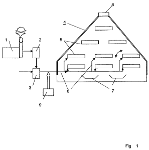
Figure 1 shows a first general form of embodiment. The exhaust gases of an
exhaust plant or industrial plant 1 are not sent through the chimney, but
firstly
through a gas washer 2. Subsequently, the exhaust containing CO2 is fed into a
pressure accumulator 3, into which water is added under pressure from approx.
1
to 10 Bar forming carbon dioxide dissolved in water. During this process, the
portion of CO2 is adjusted from 0.05 to 0.5 grams per litre water, because
this
range of values is an optimal fertilizer and excludes an acidification of the
biomass at the same time. Afterwards, the carbonated water obtained from
exhaust gas is fed via a pipeline system 6 into said tubs 5. Thereby the
filling
level is controlled such that only that much water is supplied as is used,
evaporates, or, if applicable, is metabolized by the plant. The tubs are
hereby
arranged in a partially closed system, which comprises a light-permeable wall
4.
In this context, this system is, for example, embodied pyramidally as shown in
this Figure, so that an optimal light-active surface for said photosynthesis
is
obtained. In addition, carbonated water is wetted within this system
simultaneously, so that carbonic acid again degases as CO2 (because this
process is reversible), and CO2 is offered in addition as an aerial fertilizer
in this
biomass-filled room. In this context, tubs 5 are, for example, tilting, so
that, if this
surface has formed a closed, for example, duckweed, mat, same may partially be
poured off by tilting. To this end, on the ground of tubs 5 there is arranged
a light
sensor each, which is almost completely darkened the moment the surface is
completely grown over and must be harvested.
Below there is a conveyor system, so that the poured off duckweed may be
collected automatically and be transported away for further use.
On the top of the pyramidal body, which forms the partially closed system, a
discharge flap 8 or a discharge valve is arranged in order to discharge excess
gas, i.e. also oxygen produced by photosynthesis, at the top.
In addition, waste waters from an industrial plant 1 are, if applicable, pre-
filtered
in a filter 2, and, if applicable, but not necessarily, fresh water 3 is added
and fed
11
CA 02739894 2011-04-07
into the planting tubs 5 within the greenhouse. This is carried out by a
pipeline
system 6.
Likewise, thermal water or mining water from mines can be fed in. Besides the
supply of these waters, obviously also heat is added, because these waters may
obviously be tempered.
The biomass obtained after a particular growth period of several days can thus
be harvested via scrapers or air brooms, during the process of which the
biomass drops onto conveyor belts 7.
Figure 2 shows a form of embodiment, wherein a system working as a biological
CO2 - catalytic converter as container, particularly as transportable
container, is
used. This serves a mobile application.
Container 4 may in this context even consist of folding wall elements. Also
here
obtained rapidly growing biomass (duckweed) is removed. Herein, the exhaust
gas may, stem from stationary, but also mobile, producers of exhaust gas.
Figure 3 shows an embodiment, wherein the process is applied in a hollow or a
lake. Herein the biomass 12 is mainly produced from duckweed existing on top
of
the water surface and limited by reed-like plants 11 on the rim. The
carbonated
water formed according to the invention is hereby fed into the lake and
degases
there by releasing pressure in the same manner as in the partially closed
systems referred to above, thus causing a considerable enhancement of growth.
In this process, the lake or the hollow, respectively, is covered by a light-
permeable (as described above) foil 10, in order to create a partially closed
system also by this means. This embodiment is similar to a biotope and, on the
one hand, binds CO2 from exhaust gases in the same manner by extremely fast-
growing biomass, and the produced biomass can, on the other hand, be
harvested, i.e. collected, in said short time periods also here and returned
to a
further use accordingly.
Particularly this embodiment can also be used in clarifiers in sewage
treatment
plants, as already mentioned above.
Figure 4 shows a form of embodiment, wherein the greenhouse according to the
invention was constructed around the tower 110 of a wind turbine 100. Herein,
the greenhouse 4 is very tall and erect, and the planting containers or
planting
tubs stacked in tiers are arranged inside. Thus only a comparably small basic
area is required, but a large usable volume is created. Also the incident of
light is
12
CA 02739894 2011-04-07
optimal at this highly erect form of construction. By means of an optimal use
of
light, an optimal growth is achieved.
Reference signs
1 Exhaust gas device
2 Gas washer 3 Pressure accumulator
4 Light permeable/UV light permeable wall
Planting tubs
6 Carbonated water
7 Conveyor system for biomass 8 Discharge flap/valve
9 Pipeline for feeding in mining or thermal water
Foil, light-/UV-light permeable
11 Plants growing on the sides
12 Duckweed
0 Windkraftanlage 0 Turm der Windkraftanlage