Note: Descriptions are shown in the official language in which they were submitted.
CA 02740071 2011-04-08
WO 2010/042711 PCT/US2009/059990
ARMORED TIRE AND WHEEL ASSEMBLY
CROSS-REFERENCE TO RELATED APPLICATIONS
[0001] This application claims the benefit of U.S. Provisional Patent
Application No. 611103,684, filed October 8, 2008, and U.S. Utility Patent
Application No. 12/575,786, filed October 8, 2009, the disclosures of which
are incorporated herein by reference.
BACKGROUND
[0002] This invention relates to a tire and wheel assembly for
construction and similar equipment, and in particular, to an armored tire and
wheel assembly for use on such equipment.
[0003] Rubber tires offer a number of advantages, and are widely
used on wheeled equipment, such as excavating and grading equipment.
However, under some conditions, rubber tires wear quickly, resulting in
substantial down time and cost as the rubber tires are replaced. Track
equipment has limited lives, and limited service speeds. Similarly, protective
chains for tires also have problems. They can be difficult to install and
maintain, and they also limit the speed at which the vehicle can be operated.
[0004] Attempts have been made to provide armored tires for heavy
equipment, see for example, U.S. Patent Nos. 4,132,258 for Armored Tire;
4,043,609 for Armored Tire Having a Flexible Tapered Belt Arrangement;
4,013,112 for Anchor Plate Tire Having A Sub-Lug Equipped Anchor Plate;
4,010,789 for Anchor Plate Tire; 3,776,291 for Track-Over-Tire Driving
Arrangement; 1,373,905 for Tractor Wheel; 3,500,944 for Convertible
Wheeled And Tracked Vehicle; 4,480,670 for Track Belt Assembly; 4,328,849
for Vehicle Tire With Tractive Elements; 4,258,768 for Fastener Assembly;
1
CA 02740071 2011-04-08
WO 2010/042711 PCT/US2009/059990
3,899,220 for Flexible Sealed Track Belt; 872,096 for Means For Prevent Side
Slip In Pneumatic Tires; 1,226,254 for Non-Skid Tire; 3,871,720 for Traction
Tread Band; and 4,237,950 for Tracked Armored Tire Assembly Using A Two
Pieced Grouser Retainer, the entire disclosures of which are incorporated
herein by reference. However, these devices each suffered from a variety of
disadvantages, such that none is in widespread use today.
SUMMARY
[0005] Embodiments of the present invention provide an armored tire
and wheel assembly for use on wheeled equipment, such as construction
equipment. Generally, a preferred embodiment of the armored tire and wheel
assembly comprises a wheel; a tire mounted on the wheel; a first annular
support rail disposed on one side of the tire, the first annular support rail
comprising a plurality of rail elements each pivotally connected to the
adjacent
rail elements; and a second annular support rail disposed on the other side of
the tire, the second annular support rail comprising a plurality of rail
elements
each pivotally connected to the adjacent rail elements. There are a plurality
of
shoes or pads, each extending across the surface of the tire and secured
adjacent one end to a rail element of the first annular support rail and
adjacent
the other end to a rail element of the second annular support rail.
[0006] In some preferred embodiments the tire has a plurality of
recesses therein, and at least some of the shoes or pads are adapted to
engage one of the recesses in the tire.
[0007] In another aspect, embodiments of the present invention
provide an armored belt for the tires on a wheeled vehicle. The armored belt
comprises a first annular support rail disposed on one side of the tire, the
first
2
CA 02740071 2011-04-08
WO 2010/042711 PCT/US2009/059990
annular support rail comprising a plurality of rail elements each pivotally
connected to the adjacent rail elements; and a second annular support rail
disposed on the other side of the tire, the second annular support trail
comprising a plurality of rail elements each pivotally connected to the
adjacent
rail elements. There are a plurality of shoes or pads, each adapted to extend
across the surface of the tire, secured adjacent one end to a rail element of
the first annular support rail and adjacent the other end to a rail element of
the
second annular support rail.
BRIEF DESCRIPTION OF THE DRAWINGS
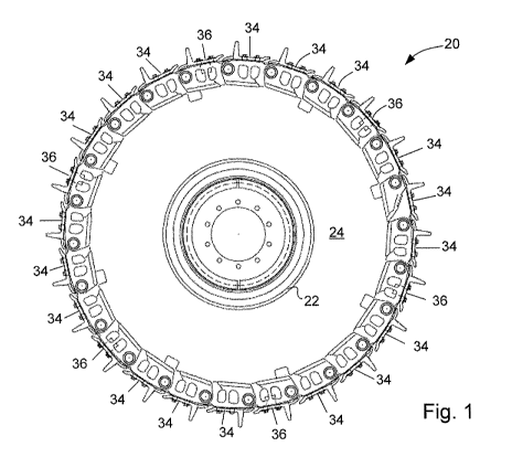
[0008] Fig. 1 is a side elevation of a preferred embodiment of an
armored tire and wheel assembly, in accordance with the principles of this
invention;
[0009] Fig. 2 is a top plan view of the armored tire and wheel
assembly in Fig. 1;
[0010] Fig. 3 is a vertical cross-sectional view of the armored tire and
wheel assembly taken along the plane of line 3-3 in Fig. 2;
[0011] Fig. 4 is a side elevation view of the armor belt for the armored
tire and wheel assembly;
[0012] Fig. 5 is a top plan view of six of the pivotally connected links
that form each of the annular support rails;
[0013] Fig. 6 is a partial plan view of a section of the armor for the
armored tire and wheel assembly;
[0014] Fig. 7A is a top plan view of a standard pad of the armor for
the armored tire and wheel assembly;
[0015] Fig. 7B is a bottom plan view of the standard pad;
3
CA 02740071 2011-04-08
WO 2010/042711 PCT/US2009/059990
[0016] Fig. 7C is a side elevation view of the standard pad;
[0017] Fig. 7D is an end elevation view of the standard pad;
[0018] Fig. 8A is a top plan view of a tire-engaging pad of the armor
for the armored tire and wheel assembly;
[0019] Fig. 8B is a bottom plan view of the tire-engaging pad;
[0020] Fig. 8C is a side elevation view of the tire-engaging pad;
[0021] Fig. 8D is an end elevation view of the tire-engaging pad;
[0022] Fig. 9A is a first side elevation view of the tire of the armored
tire and wheel assembly;
[0023] Fig. 9B is an edge elevation of the tire;
[0024] Fig, 9C is a side elevation view of the tire, on the side opposite
from that shown in Fig. 9A;
[0025] Fig. 10A is a side elevation view of the wheel;
[0026] Fig. 1 OB is top plan view of the wheel;
[0027] Fig. 10C is a vertical cross-sectional view taken along the
plane of line 1 OC-1 OC in Fig. 10B; and
[0028] Fig. 1 OD is a vertical cross-sectional view similar to Fig. IOC,
showing two hub centers.
[0029] Corresponding reference numerals indicate corresponding
parts throughout the several views of the drawings.
DETAILED DESCRIPTION
[0030] A preferred embodiment of an armored tire and wheel
assembly constructed according to the principles of this invention is
indicated
generally as 20 in Figs. 1 and 2. Generally, the assembly 20 comprises a
wheel 22 having a tire 24 thereon. The tire 24 is preferably a pneumatic tire,
4
CA 02740071 2011-04-08
WO 2010/042711 PCT/US2009/059990
but could be some other type of tire, such as a solid tire or foam-filled
tire. An
armored belt 26 is disposed over the tread and at least part of each of the
sidewalls of the tire 24. The armored belt 26 comprises first and second
annular support rails 28 and 30, connected by a track 32 comprising a
plurality of pads or shoes 34, 36 extending between the first and second
annular support rails.
[0031] As best shown in Figs. 5 and 6, each of the annular support
rails 28 and 30 comprises a plurality of links 38, each pivotally joined to
adjacent, similar links with pins 40. The pins can be solid, but are
preferably
hollow tubes to reduce weight and facilitate lubrication. The pivotally joined
links 38 are joined together in a continuous chain to form each of the annular
support rails 28 and 30. Figs. 1 and 4, show 24 links 38 pivotally joined
together to form one of the annular support rails 28 or 30, although fewer or
more links could be used depending upon the size of the tire 24 in the wheel
20. The links 38 can be custom made, but are preferably conventional links
used in conventional track drive equipment. Each of the links 38 has a
plurality of mounting holes 42, which are positioned so that the holes are on
the outer surface when the links are joined to form the rails 28 and 30.
[0032] The track 32 comprises a plurality of pads or shoes 34, 36
mounted on, and extending between, the annular support rails 28 and 30. As
shown best in Fig 3, these pads include a plurality of standard pads 34
(shown in Figs. 7A-7D) and a plurality of tire-engaging pads 36 (shown in
Figs. 8A-8D). Each of the pads 34, 36 is mounted on the mounting holes 42
on aligned links 38, in each of the first and second annular support rails 28,
30
with bolts 44.
CA 02740071 2011-04-08
WO 2010/042711 PCT/US2009/059990
[0033] As shown in Figs. 7A-7D, the standard pad 34 comprises a
generally flat panel section 46, having a plurality of mounting holes 48, and
pairs of cutouts 50 for accommodating movement of links 38. An upwardly
projecting grouser bar 52 extends across the flat panel section 46 of the pad
34. While one grouser bar 52 is shown in the Figures, the grouser bar could
be omitted, or more than one grouser bar could be provided on the pads. As
shown in Figs. 8A-8D, the tire-engaging pad 36 is similar to the standard pad
34, comprising a generally flat panel section 54, having a plurality of
mounting
holes 56, and pairs of cutouts 58 for accommodating movement of the links
38. An upwardly projecting ridge 60 extends across the flat panel section 54
of the pad 36. However, unlike the standard pads 34, the tire-engaging pads
36 have a tire-engaging spline 62 for engaging a transverse groove on the tire
24, as shown best in Fig. 3. As show in the Figures, the majority of the pads
are standard pads 34, but every fourth bar is a tire-engaging pad 36. Of
course, the relative proportions and relative positions of the standards pads
34 and the tire-engaging pads 36 could be varied.
[0034] The tire 24 can be any heavy duty tire appropriate for the
vehicle, but it is preferably adapted for use with the armor belt 26. As shown
in Figs 9A-9C, the tire 24 has first and second sidewalls 64 and 66, connected
by a tread 68. There are a plurality of elongate voids 70 forming lugs 72 on
the surface of the tread 68. These elongate voids 70 facilitate cooling of the
tires 24 when they are in service. There are also a plurality of transverse
grooves 74 for receiving the splines 62 from the tire-engaging pads 36. The
grooves 74 are spaced to accommodate the particular arrangement of splines
62 on the armor belt 26
6
CA 02740071 2011-04-08
WO 2010/042711 PCT/US2009/059990
[0035] The wheel 22 is shown in Figs. 1OA-10D, and is preferably a
conventional multi-part wheel for mounting tire 24. The wheel 22 can be
either a single or multiple mount, having one or more hub centers as
necessary, depending upon the size of the tire 24. With wider tires, it may be
desirable to secure the wheel at two or more locations to reduce bending
moments and torque on the mounting.
[0036] A preferred mounting of the wheel is shown in Fig. 11. As
shown in Fig. 11, the structure for mounting the wheel 22 on the hub of a
machine comprises a mounting ring 80 that is secured to the inside of the
wheel, such as by welding.
OPERATION
[0037] The armored tire and wheel assembly 20 is assembled by
mounting the tire 24 on a wheel 22. The armored belt 26. is then installed
over the tire by assembling the first and second annular support rails 28 and
30 adjacent either side wall of the tire 24, and connecting the links 38 of
each
of the annular support rails 28 and 30, with pads 34 and 36. The size of the
belt 26, will of course, depend on the size of the tires required by the
vehicle,
and be anywhere from 24 inches to 72 inches or more. The size of the tire 24
may need to be adjusted to accommodate the size of the outside diameter of
the annular support rails 28 and 30. This can be done by shaving the tread of
the tire, building up the treat of the tire, and to some extent, controlling
the
inflation of the tire. In at least some embodiments, it is preferred that the
diameter of the tire at the treat, match the inside diameter of the belt 26,
to
reduce or eliminate relative movement between the tread of the tire and the
inside of the belt. The splines 62 are aligned with the grooves 74 so that the
7
CA 02740071 2011-04-08
WO 2010/042711 PCT/US2009/059990
armored belt 26 turns with the tire 24 and wheel 22. The tire and wheel
assembly 20 can operate like a conventional tire and wheel, but the armored
belt 26 protects the tire 24 and extends its life. The assembly 20 can be used
with any type of wheeled vehicle, including construction equipment, mining
equipment, farming equipment, and military equipment. The assembly 20 can
be made in any size to accommodate different types and sizes of equipment.
S