Note: Descriptions are shown in the official language in which they were submitted.
CA 02740100 2011-05-10
BRASSIERE CUPS INCORPORATING PADDED UNDERWIRE ASSEMBLIES AND A
METHOD OF MAKING THE SAME
FIELD OF THE INVENTION
The present invention relates to brassiere cups, and more
particularly, to brassiere cups incorporating padded underwire
assemblies having gel pads and a method of making the same.
BACKGROUND OF THE INVENTION
Brassieres (commonly known as bras) are undergarments for
covering, restraining, shaping, and elevating the wearer's
breasts. Brassieres are designed for specific body types,
fashions, and activities. Common brassiere styles include full-
coverage, push-up, padded, demi cup, plunge, multi-way,
strapless, racerback, backless, and front closure. Regardless
of the styles and types, brassieres often contain cups with
underwires for added effects of shaping, lifting, and supporting
the breasts. In some instances, brassiere cups are integrally
attached to garments, such as tank tops, shirts, dresses, or
bathing suits.
Typically, the underwires in brassiere cups extend
partially or entirely along the lower periphery of the cups and
are positioned in a sleeve disposed about the lower periphery of
each brassiere cup. In more modern brassieres, underwires are
1
CA 02740100 2011-05-10
molded between layers of brassiere cup materials. Underwires
are generally formed of thin lengths of a fairly rigid material,
such as metal or polymeric material, having a rectangular or
rounded cross-section. The rigidity of the underwire material
is essential for lifting and holding the breasts in place. At
the same time, the materials must be flexible enough to curve
along the bottom contour of the breasts, which is a generally a
widened U-shape.
While underwires have achieved widespread usage, certain
disadvantages result from their use. During the use of a
brassiere, or other supporting garments containing underwires,
the underwires apply pressure to the wearer along the lower
periphery of the brassiere cups. Notably, the ends or tips of
the underwires create the greatest pressure on the wearer. Such
pressure points are located at areas on both sides of the
breasts proximate the wearer's armpits and areas in between the
cleavage portion of the breasts. The pressure results in
rubbing or pinching of the skin ¨ rendering prolonged use of the
brassiere uncomfortable or even painful. In a more serious
case, the underwire tips could tear through the brassiere
materials and partially expose the underwire as a result. If
the exposed underwire tips are hard or sharp, they could scrape
or puncture the clothing or skin of the wearer. Even if no such
damages occur, the exposed underwire could cause skin irritation
2
. CA 02740100 2011-05-10
to some wearers due to an allergic reaction, especially when the
underwire is made of metal.
Furthermore, the discomfort or pain accompanying the use of
underwires in brassieres often causes the wearer's movement to
be restricted. In fact, some wearers preemptively limit their
movements in order to lower their level of discomfort or chances
of getting injured. This defeats the purpose of wearing a
brassiere, because brassieres replaced corsets as a means to
free women from constricting garments.
A common practice for alleviating discomfort from brassiere
underwires is to provide a cushion along the entire length of
the underwire. Such cushions are often made of a soft foam,
cotton, or layers of fabric. Although this solution helps to
reduce the overall pressure, it does not effectively balance the
uneven pressure created by the underwire tips. Moreover, the
bulkiness of the cushion creates a space between the wearer's
breasts and the brassiere ¨ rendering the brassiere more prone
to being displaced with movements of the wearer. The cushions
may also cause brassiere to appear heavier and bulkier, which
may interfere with fashionable outer garments. Therefore, such
wearability problems are undesirable, both from practical and
aesthetic perspectives.
Another solution to the problem accompanying the use of
underwires is in a form of underwire end protectors. For
3
CA 02740100 2011-05-10
example, a cushion tip made of a relatively soft material, such
as plastic, can be attached at each end of the underwire.
However, this solution too encounters problems. Since the end
protectors are softer and more fragile than the underwire, there
comes a point where the end protector breaks. This occurs when
the brassiere is subjected to repeated use and wear created by
the movement of the wearer. When the end protector reaches its
stress threshold, it breaks and exposes a portion of the metal
underwire. Some manufacturers have tried to solve this problem
by completely encapsulating the underwire with more material
such as rubber or foam. Again, the added materials cause
displacement of the brassieres or undesirable bulkiness,
resulting in wearability problems.
There is therefore a need for underwire brassiere cups that
overcomes some or all of the previously delineated drawbacks of
prior underwire brassieres. Particularly, there is a need for
underwire brassiere cups that minimize wearability problems and
painful pressure points on the body of the wearer, while also
providing support and rigidity to the wearer.
4
CA 02740100 2013-09-10
SUMMARY OF THE INVENTION
An object of the invention is to overcome the drawbacks of
previous inventions.
Another object of the invention is to provide novel and
useful brassiere cups having gel tips that increase the comfort
and wearability to the user.
Another object of the invention is to provide novel and
useful brassiere cups having gel tips that are formed into
desired shapes.
Another object of the invention is to provide underwire gel
tips for reducing the pressure associated with the tips of the
underwire on the body of the user.
Another object of the invention is to provide novel and
useful underwire assembly comprising an underwire and gel pads
coupled thereto.
According to another aspect of the present invention, there
is provided a brassiere underwire assembly comprising: an arcuate
wire having an end; a wire casing covering at least the end of said
arcuate wire; and at least one gel pad having a center point, said
gel pad being attached to, without enclosing, said casing wherein
the end of said arcuate wire is approximately aligned with said
center point.
5
CA 02740100 2013-09-10
According to another aspect of the present invention, there is
provided an underwire brassiere cup comprising: an underwire
assembly comprising an arcuate wire having two opposing ends
and at least one gel pad disposed on at least one opposing end
of the arcuate wire; an inner layer integrally joined to the
underwire assembly such that the gel pad is substantially
disposed between the inner layer and the arcuate wire; and an
outer layer integrally joined to the inner layer and encasing
said underwire assembly.
According to another aspect of the present invention,
there is provided an underwire brassiere cup comprising: an
underwire assembly comprising an arcuate wire and at least one
gel pad, wherein said gel pad is disposed at a point of the
arcuate wire creating pressure to a wearer; an inner layer
integrally joined to an outer layer and encasing said underwire
assembly, said inner layer having a protrusion comprising said
at least one gel pad, said protrusion in the inner layer
configured to provide a cushion to protect the wearer against
the pressure created by said arcuate wire.
According to another aspect of the present invention,
there is provided a method of manufacturing a brassiere cup
having at least one gel tip comprising: providing an inner layer
and an outer layer; providing an underwire assembly comprising
5a
CA 02740100 2013-09-10
at least one gel pad attached to, without enclosing, an arcuate
wire; and molding said inner layer with said outer layer so as
to form an integrally molded composite brassiere cup, wherein
said underwire assembly is contained between said inner layer
and said outer layer.
In one embodiment, a brassiere cup for protecting a wearer
is provided, which includes gel tips. Gel tips are protrusions
formed by placing at least one gel pad between inner and outer
layers of materials. Preferably, the inner layer includes at
least one shaved gel area to house the at least one gel pad. The
gel tips are strategically placed on the brassiere to alleviate
pressure points created by the brassiere.
In another embodiment, an underwire assembly is provided
comprising an underwire having an arcuate wire coupled to at
20
5b
CA 02740100 2011-05-10
least one gel pad. Preferably, the arcuate wire is housed in a
wire casing before the at least one gel pad is attached.
Optionally, the tips of the arcuate wire may be covered with
protective paint or caps known in the art before it is housed in
the wire casing. The at least one gel pad is preferably
attached to either end of the arcuate wire. But the gel pad may
be attached anywhere along the length of the arcuate wire and
need not cover the entire length of the arcuate wire. Most
preferably, at least one gel pad is attached to each end of the
arcuate wire on a surface that faces the body of the wearer and
each end of the arcuate wire roughly corresponds with the center
of the at least one gel pad. The underwire assembly is then
incorporated into a brassiere.
In another embodiment, a protective brassiere cup is
provided comprising an underwire assembly and an inner layer
attached to an outer layer. The inner layer comprises an inner
foam material that is substantially laminated to an inner fabric
lining. The outer layer comprises an outer foam material that
is substantially laminated to an outer fabric lining. The
underwire assembly has an arcuate portion coupled to at least
two gel pads. Each of the gel pads are coupled to respective
ends of the arcuate portion. The underwire assembly is
preferably housed between the two foam layers at around a lower
peripheral area of each brassiere cup.
6
CA 02740100 2011-05-10
The properties of the material used to make the gel pads
allow the gel pads to absorb and redistribute the pressure from
the underwires. Thus, the gel pads according to the present
invention balance the uneven pressure exerted by brassiere cup
or underwires by providing maximum support and cushioning
effect. As a result, the wearer is able to enjoy the benefits
of a brassiere, including an underwire brassiere, without the
fear, discomfort and/or pain associated with it.
BRIEF DESCRIPTION OF THE DRAWINGS
A further understanding of the present invention can be
obtained by reference to preferred embodiments set forth in the
illustrations of the accompanying drawings. Although the
illustrated embodiments are merely exemplary of systems and
methods for carrying out the present invention, both the
organization and method of operation of the invention, in
general, together with further objectives and advantages
thereof, may be more easily understood by reference to the
drawings and the following description. The drawings are not
intended to limit the scope of this invention, which is set
forth with particularity in the claims as appended or as
subsequently amended, but merely to clarify and exemplify the
invention.
7
CA 02740100 2011-05-10
'
For a more complete understanding of the present invention,
reference is now made to the following drawings in which:
Figure lA is a back view of a brassiere cup assembly having
the gel tips according to the preferred embodiment of the
invention;
Figure 1B is a front view of the brassiere cup assembly
according to the preferred embodiment of the invention;
Figure 2A is a plan view of an underwire arcuate portion
housed in a wire casing in accordance with an embodiment of the
invention;
Figure 2B is a plan view of an underwire assembly
incorporated into the brassiere cup assembly of Figure 1
according to an embodiment of the invention;
Figure 3 is a perspective view of inner and outer layers of
the brassiere cup assembly of Figure 1 according to an
embodiment of the invention;
Figure 4 is a perspective view of a foam material of the
inner layer having shaved gel areas according to an embodiment
of the invention;
Figure 5 is a perspective view of a first molding process
of the inner layer according to an embodiment of the invention;
Figure 6 is a perspective view of a molded inner layer with
its foam material covered with glue according to an embodiment
of the invention;
8
CA 02740100 201105-10
Figure 7 is a perspective view of a composite inner layer
comprising the underwire assembly shown in Figure 2B according
to an embodiment of the invention;
Figure 8 is a perspective view of the outer layer
comprising a glue-covered foam material layer according to an
embodiment of the invention;
Figure 9 is a perspective view of a second molding process
of the composite inner layer shown in Figure 7 with the outer
layer according to an embodiment of the invention;
Figure 10 is a cross-sectional view illustrating one of the
shaved gel areas of the inner layer and a portion of the outer
layer having the underwire assembly therebetween according to an
embodiment of the invention;
Figure 11 is a perspective view of several shapes for the
gel tips according to alternate embodiments of the invention.
DETAILED DESCRIPTION OF THE INVENTION
The present invention may be understood more readily by
reference to the following detailed description of preferred
embodiments of the invention. However, techniques, systems and
operating structures in accordance with the present invention
may be embodied in a wide variety of forms and modes, some of
which may be quite different from those in the disclosed
embodiments. Consequently, the specific structural and
9
CA 02740100 2011-05-10
functional details disclosed herein are merely representative,
yet in that regard, they are deemed to afford the best
embodiments for purposes of disclosure and to provide a basis
for the claims herein, which define the scope of the present
invention. It must be noted that, as used in the specification
and the appended claims, the singular forms "a", "an", and "the"
include plural referents unless the context clearly indicates
otherwise. In the following description, for purposes of
explanation, numerous specific details are set forth in order to
provide a thorough understanding of the present invention. It
may be evident, however, that the present invention may be
practiced without these specific details. In other instances,
well-known structures and devices are shown in block diagram
form in order to facilitate describing the present invention.
As used herein, a "brassiere" refers not only to an
undergarment, but also an integral piece of a garment to support
and give contour to the breasts. Examples of such garments
include, but are not limited to, shirts, tank tops, camisoles,
other conventional tops, dresses, leotards, sportswear, bathing
suits, and the like.
As used herein, the term "inner layer" of a brassiere
refers to the layer that adjoins the body when a wearer wears
the brassiere. Accordingly, the term "outer layer" refers to
the layer that is further away from the body of the wearer.
CA 02740100 2011-05-10
As used herein, the term "back side" of a brassiere refers
to the side of the brassiere that immediately adjoins the body
when a wearer wears the brassiere. Accordingly, the term "front
side" of a brassiere refers to the side which is opposite the
back side and faces away from the wearer.
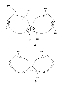
Referring initially to Figure 1A, there is shown a back
side of a brassiere cup assembly 100. According to a preferred
embodiment of the invention, the brassiere cup assembly 100
includes two brassiere cups 105 and 110 having an underwire
assembly (hidden) placed between inner and outer layers of each
brassiere cup, with the inner layer being closer to the wearer.
Optionally, additional layer(s) and/or padding material may be
present between the inner and outer layers.
Preferably, each of brassiere cups 105 and 110 bears novel
gel tips, 115, 120, 125, and 130. The gel tips according to the
present invention balance the uneven pressure applied by a
brassiere by providing support and cushioning effect at pressure
points created by the brassiere underwire. The gel tips 115 and
120 comprise gel pads that are integrally attached to an arcuate
wire, which is placed between the inner and outer layers.
Similarly, gel tips 125 and 130 include integrally placed gel
pads on an arcuate wire of the brassiere cup 110. Since gel
tips 115, 120, 125, and 130 do not cover the entire length of
the underwire, the brassiere cups 105 and 110 sit closer to the
11
CA 02740100 2011-05-10
body of the wearer. Therefore, the gel tips according to the
present invention minimize the chances of the brassiere cups
being displaced. Furthermore, while providing cushion, the less
bulky appearance of the brassiere cups of the present invention
allows the brassiere cups to be worn under many fashionable
outer garments. It must be noted that although Figure lA shows
a preferred embodiment with four gel tips 115, 120 125, and 130
placed at locations corresponding to all four ends of the
arcuate wire, not all ends of the arcuate wire need to have a
gel tip. Thus, it is conceivable that only one end of the
underwire has a gel tip according to the present invention.
Moreover, it should be appreciated that gel tips may be placed
on other parts of the underwire and/or other parts of the
brassiere to minimize pressure points from the brassiere.
Preferably, the gel pads are not visible from the back side
of the brassiere as they are covered by the inner layer.
However, the volume of gel pads may cause the formation of
protruded gel tips on the surface of a brassiere cup.
Alternatively, gel tips may be flat with respect to the surface
of the inner layer of the brassiere cups 105 and 110. According
to a preferred embodiment of the invention, gel tips protrude
from the back side of the brassiere cups toward the wearer to
create cushion-like bumps. More preferably, the protruding gel
tips have predetermined shapes formed through molding process as
12
CA 02740100 2011-05-10
described below. It is noted that although gel tips 115, 120,
125, and 130 bear a tear-drop shape in Figure 1A, it is
contemplated that gel tips, independently of one another, may
utilized different shapes. Nonlimiting examples of various
shapes for the gel tips are shown in Figure 11, which is
discussed in detail below. On the other hand, the front side of
the brassiere cups 105 and 110 is preferably smooth and bears no
apparent bumps from the gel pads as illustrated in Figure 1B.
Referring to Figures 2-9, there is shown a method of
constructing brassiere cup assembly 100 by utilizing various
assemblies of layers and underwires according to a preferred
embodiment of the invention.
Referring to Figure 2A, an underwire comprising an arcuate
wire 405 (shown as hidden) contained inside a wire casing 425 is
provided. It should be appreciated that it is not necessary for
the wire casing 425 to completely cover the arcuate wire 405.
The wire casing 425 may cover only a portion of the arcuate wire
405 for additional protection for the wearer. The arcuate wire
405 may be made of any conventional material known in the art,
including, but are not limited to, metal, polymeric material,
and a mixture thereof. The arcuate wire 405 and/or the wire
casing 425 generally has a flat cross-section such as oval or
rectangular and includes a first side 430 and an opposing second
side (not shown). However, it is also conceivable to use an
13
CA 02740100 2011-05-10
arcuate wire having non-flat cross sections including, but not
limited to, round, triangular, and other non-flat polygonal
shapes. The arcuate wire could also have varying cross-sections
and widths along its length. The tips of the arcuate wire 405
may be covered with protective paint, plastic caps, or any other
material known in the art. According to a preferred embodiment,
the arcuate portion 405 is inserted into a thin wire casing 425
and bar tacked 440 at both ends using a conventional method
known in the art.
Figure 2B illustrates an underwire assembly 420 which
comprises an underwire as shown in Figure 2A having gel pads 400
attached thereto according to a preferred embodiment of the
present invention. The gel pad may be made of polyurethane gel,
silicone gel, or the like. Preferably, the gel pad comprises a
gel disc sandwiched between two polyurethane films.
Specifically, the gel pad is made by first placing a first
polyurethane film on a flat surface and then a relatively
smaller gel disc on top of the film. A second polyurethane
film, which is preferably about the same size as the first
polyurethane film, is then placed on top of the gel disc. The
edges of the polyurethane films are sealed by a heat nozzle or
any other methods known in the art to envelop the polyurethane
gel disc. The gel pad is created by trimming the excess films
around the encased gel disc.
14
CA 02740100 2011-05-10
The gel disc is preferably made of polyurethane gel
comprising styrene thermoplastic elastomer, tackifier, and
phenolic antioxidant. Such polyurethane gel shows superior
pressure redistribution capability compared to a general memory
foam. The polyurethane gel is also thought to significantly
buffer shearing force between the wearer and the brassiere inner
layer, thereby rendering the prolonged use of the brassiere more
comfortable compared to a conventional brassiere. The preferred
polyurethane gel that may be utilized to make the gel pads
according to the present invention is Exgel , available from
Kaji Corporation in Japan. Exgel is an extremely flexible gel
having both solid and liquid properties. Its shape can be
easily distorted, but it always retains its original shape after
a period of time. Moreover, Exgel is resilient enough not be
completely flattened out by an exerted force and maintains it
functions. Exgel also has an exceptional impact absorbing
capability, which is 5 to 10 times greater than a general memory
foam.
For assembling the underwire assembly 420, one side of the
gel pad 400 is softened by applying heat thereto. The softened
surface of the gel pad 400 attaches to the first side 430 of the
wire casing 425 containing the arcuate wire 405. Preferably,
each gel pad 400 is attached to each end 410 and 415 of the
arcuate wire 405 and only partially covers the first side 430 of
CA 02740100 2011-05-10
the arcuate wire 405. More preferably, the underwire assembly
420 comprises the gel pad 400 attached substantially to the
first side 430 of the wire casing 425. If the arcuate wire 405
does not have a flat cross section, the side to which the gel
pad 400 is attached is designated as the first side 430.
Moreover, the center of the gel pad 400 roughly corresponds with
either end 410 and 415 of the arcuate wire 405. This preferred
placement of the gel pad 400 on either end 410 or 415 can be
also seen in Figure 10, where the end 410 of the arcuate wire
405 aligns with the center point C of the gel pad 400. In an
alternative embodiment, two or more gel pads may be used for
each end 410 and 415. Optionally, additional gel pads 400 may
be attached to the first side of the arcuate wire 405 at a
location in addition to ends 410 or 415. Preferably, the
underwire assembly 420 is incorporated into a lower peripheral
area of the brassiere cup.
As shown in Figure 3, brassiere cup assembly 100 (Figure 1)
comprises at least the inner layer 210 and the outer layer 205.
Preferably, the size of the outer layer 205 is about the same as
that of the inner layer 210. Each layer preferably comprises a
polyurethane foam material attached to a fabric lining.
However, it should be appreciated that either layer,
independently of one another, may comprise a polyurethane foam
material without the fabric lining. Furthermore, it is
16
CA 02740100 2011-05-10
conceivable that either layer is made of one or more of other
materials known in the art that are suitable for making
brassiere cups. According to a preferred embodiment, outer
layer 205 includes polyurethane foam material 215 laminated to a
substantially coextensive outer fabric lining 220. Similarly,
inner layer 210 preferably includes polyurethane foam material
225 laminated with a substantially coextensive fabric lining
230. The polyurethane foam materials 215 and 225 need not have
a same chemical composition. Similarly, the fabric lining 220
and 230 need not be made of a same material.
In one non-limiting example, the polyurethane material 215
and 225 are laminated to each fabric lining 220 and 230,
respectively, by loading a polyurethane foam roll and a fabric
roll on a lamination machine. After glue is applied to one
surface of the polyurethane foam roll, the fabric lining is
bonded thereto by using a pressing roller. The lamination may
preferably be rotary lamination. However, the surfaces may be
laminated through spray lamination, powder lamination, hot melt
lamination, or other methods of lamination known in the art.
Polyurethane foam materials 215 and 225 are formed through
polymerization of at least one monomer containing hydroxyl
groups and at least one monomer containing isocyanate functional
groups. In another non-limiting embodiment, fiberfill made of
polyester fiber may also be utilized to replace or supplement
17
CA 02740100 2011-05-10
the polyurethane foam material. Fabric linings 220 and 230 may
comprise 100% polyester interlock. Alternatively, fabric
linings 220 and 230 may comprise, independently of one another,
100% nylon or synthetic and/or natural fiber with elastane, such
as Spandex, LYCRA , ROICAO, CREORAO, DorlastanTM, FujiboTM or
similar types of materials.
As shown in Figure 4, the inner layer 210 has the exposed
polyurethane foam material 225 with four independent shaved gel
areas 305, 310, 315, and 320. The shaved gel areas are created
to accommodate the gel pads therewithin. In the finished
brassiere cup assembly 100, each shaved gel area preferably
corresponds to individual gel tips. Thus, it is also
conceivable to have less than or more than four shaved gel
areas, depending on the desired number of gel tips. Referring
specifically to Figure 4, each of the shaved gel areas 305, 310,
315, and 320 houses the corresponding gel pad 400 of the
underwire assembly 420. Thus, one can see that the brassiere
cup assembly 100 as shown in Figure 1 bears the gel tip 115
corresponding with the shaved gel area 320, the gel tip 120
corresponding with the shaved gel area 315, the gel tip 125
corresponding with the shaved gel area 310, and the gel tip 130
corresponding with the shaved gel area 305.
The shaved gel areas preferably are shaven in a shape that
roughly corresponds to the desired shape for the resulting gel
18
CA 02740100 2011-05-10
tips. For example, if tear-dropped shaped gel tips as shown in
Figure lA are desired, the corresponding shaved gel areas are
shaved in oval or similar circular shapes instead of squared or
rectangular shapes. The shaved gel areas may be created with a
blade or shaving board having engraved predetermined shapes to
partially remove polyurethane foam material. However, it should
also be appreciated that other methods of shaving polyurethane
foam material may be employed to create the shaved gel areas.
Preferably, shaved gel areas are not visible from the fabric
lining side 230 of the inner layer 210. Thus, the depth of
shaved areas should not exceed the width of the polyurethane
foam material 225. This is further illustrated in Figure 10.
Generally, the shaved gel areas, if they are roughly circular,
have a diameter of about 15 mm and a depth of about 4 mm.
However, other sized shaved areas may be utilized to accommodate
larger or smaller gel pads.
Referring now to Figure 5, the inner layer 210 with shaved
gel areas 305, 310, 315, and 320 is introduced into a first
molding press (not shown) and molded to form a molded inner
layer 620 having at least one brassiere cup portion 610 and 615.
Preferably, the first molding press comprises a top molding
panel and a bottom molding panel. The two panels are preferably
preheated at designated temperatures and comprise aluminum, but
other suitable material known in the art may be used to make the
19
CA 02740100 2011-05-10
panels of the first molding press. The inner layer 210 is
positioned into the molding press such that the polyurethane
foam material 225 abuts the top molding panel having concave
surfaces, and the fabric lining side 230 is positioned on the
bottom molding panel having convex surfaces. Preferably, the
top molding panel also contains bulged areas that fit inside the
shaved gel areas. Moreover, the bulged areas have shapes that
correspond to desired shapes for the resulting gel tips. The
bottom molding panel preferably contains recessed areas, also in
the shape desired for the resulting gel tips. For example, the
top and bottom molding panels in Figure 5 have corresponding
bulged and recessed areas in tear-dropped shapes.
During the first molding process, the top and bottom
molding panels sandwich the inner layer 210 such that the inner
layer 210 becomes a molded inner layer 620 having brassiere cup
portions 610 and 615, whose convex sides are on the same side as
the shaved gel areas 305, 310, 315, and 320. The bulged areas
of the top molding panel push the shaved gel areas 305, 310,
315, and 320 deeper into the inner layer 210 and form
protrusions on the fabric lining side 230. The recessed areas
of the bottom molding panel accommodate the formed protrusions.
Notably, the forces applied simultaneously by both the bulged
and recessed areas of the top and bottom molding panel,
respectively, function to shape the protrusions into tear-drop
CA 02740100 2011-05-10
shapes while the brassiere cup portions 610 and 615 are being
formed. Each of the brassiere cup portions 610 and 615 would
eventually become brassiere cups 110 and 105 (Figure 1),
respectively. It should be appreciated that various molding
press' shape and depth can be utilized to define the shape of
the resulting brassiere cups and/or their push-up levels.
Furthermore, it is possible to adjust the dimensions of the
inner layer and the design of the first molding press to create
only one breast cup portion or more than one set of breast cup
portions in one inner layer. Alternatively, one inner layer
could contain a plurality of only one of brassiere cup portions
610 and 615, so as to obtain a plurality of only one of
brassiere cups 110 and 105 (Figure 1).
With reference to Figure 6, after the three-dimensional
brassiere cup portions 610 and 615 are formed, glue is sprayed
or applied to the convex side (i.e., the side of polyurethane
foam material 225) of the molded inner layer 620. Preferably,
the glue is a solvent based glue and may be any one or more of
water-based glue, thermal plastic glue, Thermoplastic
Polyurethane (TPU) glue, Polyurethane (PU) glue, or the like.
As shown in Figure 7, two underwire assemblies 420 are
placed on the glue-covered side of the molded inner layer 620 at
around the lower regions of the brassiere cup portions 610 and
615. Notably, the underwire assemblies 420 are placed such that
21
CA 02740100 2011-05-10
the gel pads 400 face toward, not away from, the molded inner
layer 620. Furthermore, each of the gel pads 400 reside within
the shaved gel areas 305, 310, 315, and 320. The resulting
assembly is a composite inner layer 720 comprising the underwire
assemblies 420 and the molded inner layer 620. It should be
appreciated that the location of the underwire assemblies 420
within the composite inner layer 720 corresponds with the lower
contour region of the wearer's breasts. Thus, the resulting
brassiere cups 105 and 110 (Figure 1) will have the underwire
assemblies 420 at their lower peripheral areas so as to provide
support and lift to the wearer's breasts.
Figure 8 illustrates the outer layer 205 with polyurethane
foam material 215 in a substantially planar form and ready for
molding. Glue is applied to the exposed side of the
polyurethane foam material 215 of the outer layer 205, directly
opposite the side of the fabric lining 220. Preferably, the
glue is a solvent based glue and may be one or more of water-
based glue, thermal plastic glue, TPU glue, PU glue, or the
like.
As shown in Figure 9, the outer layer 205 is provided for
molding with the composite inner layer 720 so as to completely
encase the underwire assemblies 420 between the outer layer 205
and the composite inner layer 720. Notably, the outer layer 205
is positioned with respect to the composite inner layer 720 such
22
CA 02740100 2011-05-10
that the glue-covered side 215 of the outer layer 205 (i.e., the
side of the exposed polyurethane foam material) comes in contact
with the glue covered side 225 of the composite inner layer 720
during this second molding process. However, it should be
appreciated that one or more additional layer or a padding
material may be placed between the composite inner layer 720 and
the outer layer 205 without departing from the scope of the
invention. It is contemplated that a stabilizer tricot (not
shown) may be placed at the ends of the underwire assemblies 420
to hold the assemblies 420 in place during this second molding
process. The outer layer 205 is molded together with the
composite inner layer 720 to form a molded composite layer
having brassiere cup portions 610 and 615.
The second molding press used to integrally mold the
composite inner layer 720 and the outer layer 205 preferably
comprises a first molding panel and a second molding panel (not
shown). The two panels are preferably preheated at designated
temperatures and comprise aluminum, but other suitable material
known in the art may be used to make the panels of the second
molding press. The first molding panel comes in contact with
the fabric layer side 220 of the outer layer 205 and contains
concave surfaces for forming brassiere cup portions 610 and 615.
The second molding panel, having convex surfaces, comes in
contact with the fabric layer side 230 of the composite inner
23
CA 02740100 2011-05-10
layer 720. Additionally, the second molding panel preferably
contains recessed areas. These recessed areas are necessary in
order to accommodate the formed protrusions on the fabric lining
side 230 of the composite inner layer 720. Notably, the shapes
of the recessed areas correspond to the shapes of the
protrusions formed during the first molding process. Thus, the
recessed areas function to maintain the shapes of the
protrusions on the fabric lining side 230 as the gel pads 400
are being pushed into the shaved gel areas 305, 310, 315, and
320. The gel tips 115, 120, 125, and 130 as shown in Figure lA
all have tear-drop shapes, because the corresponding recessed
areas of the second molding panel also had indented tear-drop
shapes.
After the second molding process, the integrally molded
composite layer comprising the outer layer 205 and the composite
inner layer 720 is trimmed to remove the excess material and
create brassiere cups 105 and 110. The cups 105 and 110 are
preferably smooth with no apparent bumps visible on the front
side 220. However, as illustrated in Figure 1A, the back side
of the brassiere cups 110 and 105 preferably bear protruded gel
tips 115, 120, 125, and 130. Preferably, the bulk of the gel
pad material 400 is present on the first side 430 of the arcuate
wire 405, so that the wearer of the brassiere cups will have a
maximum support from the gel tips by having more gel pad
24
CA 02740100 2011-05-10
material 400 closer to her than on the opposing second side of
the arcuate wire 405. The brassiere cup assembly according to
the present invention may be further incorporated into brassiere
products known in the art including undergarments, garments such
as tank tops, camisoles, other conventional tops, dresses,
leotards, sportswear, bathing suits, and the like. As such,
the brassiere cup assembly may be attached to conventional
brassiere components such as hooks, straps, fabric, or other
auxiliary components to produce a final brassiere product.
A cross-sectional view of the shaved gel area 320 as shown
in Figure 10 provides a clear view of the configuration of
various components in the area proximal to the shaved gel area
320. However, it should be appreciated that the configuration
is also applicable to other shaved gel areas according to the
present invention. According to a preferred embodiment of the
invention, the wire casing 425 contains the arcuate wire 405,
whose end 410 aligns approximately with center point C of the
gel pad 400. The underwire assembly 420 rests on the
polyurethane foam material side 225 of inner layer 210. More
specifically, the underwire assembly is placed such that the gel
pad 400 is housed within the shaved gel area 320. The
polyurethane foam material 225 of inner layer 210 faces the
polyurethane foam material 215 of the outer layer 205. This
ensures that after the second molding process the brassiere cup
CA 02740100 2011-05-10
portions 610 and 615, which correspond to brassiere cups 110 and
105, respectively, will have the back and front sides bearing
fabric linings 230 and 220, respectively.
Referring to Figure 11, there are shown alternate
embodiments of the invention. Particularly, the gel tips
according to the present invention, independently of one
another, may be formed of various shapes. Examples of such
shapes include, but are not limited to, a circle 1005, an oval
1010, a triangle 1015, a heart 1020, a small triangle 1025, a
half-circle 1030, a half-oval 1035, a tear-drop 1040, and a
small heart 1045. It should be appreciated that the shape of
shaved gel areas as well as bulged and recessed areas of the
molding panels may be modified to form the desired shapes for
the gel tips. All other aspects of the invention may remain the
same as the embodiment shown and described in Figures 1-9,
without departing from the scope of the invention.
It should also be appreciated that other similar methods,
components, and equipments may be utilized to manufacture the
brassiere cup assembly without departing from the spirit of the
present invention. While the present invention has been
described with reference to the preferred embodiment and
alternative embodiments, which embodiments have been set forth
in considerable detail for the purposes of making a complete
disclosure of the invention, such embodiments are merely
26
CA 02740100 2013-09-10
exemplary and are not intended to be limiting or represent an
exhaustive enumeration of all aspects of the invention.
10
20
27