Language selection

Search

Patent 2740132 Summary

Third-party information liability

Some of the information on this Web page has been provided by external sources. The Government of Canada is not responsible for the accuracy, reliability or currency of the information supplied by external sources. Users wishing to rely upon this information should consult directly with the source of the information. Content provided by external sources is not subject to official languages, privacy and accessibility requirements.

Claims and Abstract availability

Any discrepancies in the text and image of the Claims and Abstract are due to differing posting times. Text of the Claims and Abstract are posted:

  • At the time the application is open to public inspection;
  • At the time of issue of the patent (grant).
(12) Patent Application: (11) CA 2740132
(54) English Title: WATER MANIFOLD
(54) French Title: COLLECTEUR D'EAU
Status: Deemed Abandoned and Beyond the Period of Reinstatement - Pending Response to Notice of Disregarded Communication
Bibliographic Data
(51) International Patent Classification (IPC):
  • F16L 47/32 (2006.01)
  • E03C 1/02 (2006.01)
  • F16L 3/02 (2006.01)
  • F16L 3/13 (2006.01)
  • F16L 41/02 (2006.01)
(72) Inventors :
  • MCKENZIE, DANIEL (Canada)
(73) Owners :
  • DIE MOLD TOOL LIMITED
(71) Applicants :
  • DIE MOLD TOOL LIMITED (Canada)
(74) Agent: VALERIE G. EDWARDEDWARD, VALERIE G.
(74) Associate agent:
(45) Issued:
(22) Filed Date: 2011-05-11
(41) Open to Public Inspection: 2012-11-11
Availability of licence: N/A
Dedicated to the Public: N/A
(25) Language of filing: English

Patent Cooperation Treaty (PCT): No

(30) Application Priority Data: None

Abstracts

English Abstract


A manifold housing which includes an inlet end for receiving fluid in
communication with a main channel defined within the housing. The housing
includes a series of outlets in fluid communication with the main channel. The
outlets are for connecting outlet pipes thereto, wherein the inlet end having
inlet threads for receiving standard pipe threaded fittings therein.
Preferably
the outlets of the manifold housing includes upwardly projecting lugs attached
at one end to a bottom of the outlet, wherein the lugs for abutting with a lug
end of a crimp ring used to secure an outlet pipe to the outlet.


Claims

Note: Claims are shown in the official language in which they were submitted.

THE EMBODIMENTS OF THE INVENTION IN WHICH AN EXCLUSIVE
PROPERTY OR PRIVILEGE IS CLAIMED IS DEFINED AS FOLLOWS:
1. A manifold housing comprising:
a) a housing which includes an inlet end for receiving fluid in
communication with a main channel defined within the
housing;
b) a series of outlets in fluid communication with the main
channel, the outlets for connecting outlet pipes thereto;
c) the inlet end having inlet threads for receiving standard pipe
threaded fittings therein.
2. The manifold housing claimed in claim 1 wherein the outlets include
upwardly projecting lugs attached at one end to a bottom of the outlet, the
lug for abutting with a lug end of a crimp ring used to secure an outlet pipe
to the outlet.
3. The manifold housing claimed in claim 1 wherein the main channel tapered
along the longitudinal axis such that the main channel larger at the inlet
end.
4. The manifold housing claimed in claim 1 wherein the housing further
includes an exit end having exit threads for receiving standard pipe
threaded fittings therein

5. The manifold housing claimed in claim 1 wherein the housing further
includes a tapping port which includes a tapping lug and a taping hole.
6. The manifold housing claimed in claim 1 further includes a manifold clip
for co-operatively clipping onto the manifold.
7. The manifold housing claimed in claim 6 wherein the body further includes
side ribs for co-operatively engaging with the manifold clip.
8. The manifold housing claimed in claim 7 wherein the clip further includes
a base and a right finger which includes a right indent and a left finger
which includes a left indent, the indents for co-operatively engaging onto
the side ribs.
9. The manifold housing claimed in claim 5 wherein the body further includes
a top rib and a bottom rib for co-operatively engaging with the manifold
clip.
11

Description

Note: Descriptions are shown in the official language in which they were submitted.


CA 02740132 2011-05-11
WATER MANIFOLD
Field of the Invention
[0001] The present invention relates to water manifolds and in particular
relates
to pressurized water manifolds manufactured from poly phenyl sulphone.
Background of the Invention
[0002] There is a shift in materials used for distributing potable water in
buildings across North America. Currently most plumbing and potable water
fittings are made from copper and/or brass. Due to California and other state
legislation there is a shift from copper and brass fittings to the use of poly
phenyl
sulphone fittings. In addition traditional copper piping is moving towards PEX
flexible tubing for applications in the distribution of potable water in
residential
and commercial buildings. PEX stands for cross linked poly ethylene and is a
very durable tubing especially under hot and cold water extremes. PEX is used
to
replace copper tubing and allows for a significant savings both in cost as it
relates
copper and it's ease in installation, which converts to time saved.
[0003] There is a need for fittings and specifically manifolds, which can be
used
in conjunction with the PEX tubing. To date the only suitable material, which
has
been identified is poly phenyl sulphone and there is little experience and/or
technology in the market place currently in regard to the manufacture of
fittings
from poly phenyl sulphone.
2

CA 02740132 2011-05-11
Brief Description of the Drawings
[0004] The present concept will now be described by way of example only with
reference to the following drawings in which;
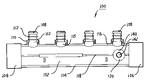
Figure 1 is a side elevational view of a four outlet manifold.
Figure 2 is an end plan view of the manifold shown in Figure 1.
Figure 3 is a schematic cross sectional view of the manifold shown in
Figure 1.
Figure 4 is a schematic cross sectional view of the manifold shown in
Figure 1 together with an outlet pipe deployed thereon showing the use of a
crimp ring.
Figure 5 is a side perspective view of the manifold shown in Figure 1.
Figure 6 is a top side perspective view of the manifold shown in Figure 1.
Figure 7 is a side elevational view of a manifold clip.
Figure 8 is a top side perspective view of the manifold clip shown in Figure
1.
Figure 9 is a top perspective view of the manifold shown in Figure 1
together with two manifold clips, which are shown in Figure 7 wherein the
manifold is deployed with the manifold clips.
3

CA 02740132 2011-05-11
Figure 10 is an alternate embodiment of the present invention a six outlet
manifold with a closed end.
Figure 11 is a end plan view of the manifold shown in Figure 12.
Figure 12 is a side cross sectional view of the six outlet manifold shown in
figure 10.
Detailed Description of the Preferred Embodiments
[0005] The present concept is shown generally as manifold 100 in Figure 1 and
manifold 300 in Figure 10.
[0006] There further is an accessory to both manifold 100 shown in Figure 1
and manifold 300 shown in Figure 10 namely a manifold clip shown generally as
200 in Figures 7 and 8.
[0007] Referring first of all to Figure 1 manifold shown generally as 100
includes the following major components namely housing 102, inlet end 104,
exit
end 106, four outlets 108 having lugs 110 and bands 112. Lugs 110 emanate from
a bottom 115 of outlet 108 and project upwardly. There may be one or more lugs
surrounding each outlet 108 but preferably there are two as depicted.
4

CA 02740132 2011-05-11
[0008] Manifold 100 further includes a bottom rib 114, a top rib 116, two side
ribs 118 a tapping port 120 which includes a tapping lug 140 and a tapping
hole
142.
[0009] Referring now to Figure 3 which is a schematic diagram of manifold 100
shown in cross sectional view. Manifold 100 includes inlet threads 126 and
exit
threads 128 which are standard pipe threads adapted to receive male threaded
pipe
fittings. Manifold 100 has a longitudinally oriented main channel 122 which is
slightly larger at inlet end 104 than at exit end 106 which is shown as taper
124.
In practice it is found that the angle subtended by taper 124 is between 3 and
8
degrees. Preferably the angle is 5 degrees over the length of main channel
122.
[00010] Referring now to Figure 4 manifold 100 is shown together with an
outlet
pipe 132 deployed on one of the outlets 108.
[00011] The reader will note that each outlet 108 includes a lug 110 which
acts as
a stop for the lug end 136 of crimp ring 134. The reader will also note that
each
outlet 108 includes two bands 112 which aid in the sealing of outlet pipe 132
around outlet 108 by using crimp ring 134.
[00012] Housing 102 is generally cylindrical in shape and includes an inlet
end
104 which includes a standard pipe threaded inlet thread 126 and standard pipe

CA 02740132 2011-05-11
threaded exit threads 128. Commercially available standard pipe fittings
having
standard pipe threads can be threaded into either inlet end 104 or exit end
106.
Therefore manifold 100 can be adapted to fit almost any incoming sized piping
that is presently available for industrial and commercial potable water
installations
in buildings.
[00013] Referring now to Figures 7 and 8 which depicts a manifold clip shown
generally as 200 which includes a base 202, right arm 204, a left arm 206, a
right
finger 208 which includes a right indent 210 and chamfered portion 230.
Manifold clip 200 further includes a left finger 212 having a left indent 214
and an
upper rib 215. Left arm 206 includes a first upright 216 and a second upright
218
which are connected near the top by left finger 212 and is interconnected with
right arm 204 with cross member 220.
[00014] As best shown in Figure 8 manifold clip 200 further includes a right
aperture 224 and a left aperture 226 for fastening the base 202 to any
suitable sub-
strait.
[00015] Figure 9 shows two manifold clips 200 deployed together with manifold
100. The reader will note that the side ribs 118 of manifold 100 engage with
right
indent 210 and left indent 214 of manifold clip 200 thereby placing manifold
100
in the clipped position 221. The right indent 210 and left indent 214 of
manifold
6

CA 02740132 2011-05-11
clip 200 may also engage with the top rib 116 and bottom rib 114 in similar
fashion as with the side ribs 118.
[00016] In order to put manifold 100 into clip position 221 firstly a side rib
118
is placed into left indent 214 and then the other side rib 118 is slideably
urged
along chamfered portion 230 of right finger 208 until the side rib 118 engages
with
right indent 210.
[00017] Referring now to Figures 10, 11 and 12 which shows manifold 300
which includes the following major components namely housing 302 and inlet end
304, a closed end 306, six outlets 308 each having lugs 310 and bands 312.
[00018] Housing 302 further includes a bottom rib 314 and a top rib 316.
Referring now to Figure 12 which shows manifold 300 in schematic cross
sectional view and includes a housing 302 having a main channel 322 which is
larger at inlet end 304 and slightly smaller at closed end 306. The main
channel
322 therefore is tapered which is depicted as taper 324 in Figure 12. This
taper
preferably is anywhere from 3 to 8 degrees and preferably is 5 degrees.
[00019] Manifold 300 further includes inlet threads 326 for receiving any
standard pipe fittings therein.
7

CA 02740132 2011-05-11
[00020] Bottom ribs 314 and top ribs 316 are designed to engage with right
indent 210 and left indent 214 of manifold clip 200 therefore although not
shown
manifold clips 200 can be used either with manifold 100 and/or with manifold
300.
[00021] In most respects manifold 300 is very similar if not the same as
manifold
100 with the exception that manifold 100 includes both a threaded inlet end
104
and a threaded exit end 106 wherein manifold 300 only includes a threaded
inlet
end 304 and a closed end 306.
[00022] Manifold 100 could also be fitted with outlets 108 projecting from the
top and bottom of housing 102. Likewise manifold 300 could be fitted with only
outlets 308 projecting from the top of housing 302 rather than the top and
bottom
as shown in the Figures.
[00023] The reader will note that the manifolds 100 could be made larger or
smaller with fewer or more outlets 108 which are normally evenly spaced along
the housing 102 in the case of manifold 100 or the housing 302 in the case of
manifold 300. In addition outlets can be fitted to extend out of the top
portion of
housing 102 as shown in the examples of manifold 100 or outlets could be shown
to extend out of the top and bottom portions of housing 302 as shown for
manifold
300.
8

CA 02740132 2011-05-11
[00024] It should be apparent to persons skilled in the arts that various
modifications and adaptation of this structure described above are possible
without
departure from the spirit of the invention the scope of which defined in the
appended claim.
9

Representative Drawing
A single figure which represents the drawing illustrating the invention.
Administrative Status

2024-08-01:As part of the Next Generation Patents (NGP) transition, the Canadian Patents Database (CPD) now contains a more detailed Event History, which replicates the Event Log of our new back-office solution.

Please note that "Inactive:" events refers to events no longer in use in our new back-office solution.

For a clearer understanding of the status of the application/patent presented on this page, the site Disclaimer , as well as the definitions for Patent , Event History , Maintenance Fee  and Payment History  should be consulted.

Event History

Description Date
Inactive: Adhoc Request Documented 2016-11-28
Revocation of Agent Request 2016-11-03
Appointment of Agent Request 2016-11-03
Application Not Reinstated by Deadline 2016-05-11
Time Limit for Reversal Expired 2016-05-11
Deemed Abandoned - Failure to Respond to Maintenance Fee Notice 2015-05-11
Letter Sent 2014-05-13
Reinstatement Requirements Deemed Compliant for All Abandonment Reasons 2014-05-13
Deemed Abandoned - Failure to Respond to Maintenance Fee Notice 2014-05-12
Inactive: Office letter 2013-11-28
Letter Sent 2013-10-30
Reinstatement Requirements Deemed Compliant for All Abandonment Reasons 2013-10-29
Revocation of Agent Requirements Determined Compliant 2013-10-21
Inactive: Office letter 2013-10-21
Appointment of Agent Requirements Determined Compliant 2013-10-21
Appointment of Agent Request 2013-10-07
Revocation of Agent Request 2013-10-07
Letter Sent 2013-07-11
Inactive: Single transfer 2013-06-12
Letter Sent 2013-05-30
Inactive: Single transfer 2013-05-13
Deemed Abandoned - Failure to Respond to Maintenance Fee Notice 2013-05-13
Application Published (Open to Public Inspection) 2012-11-11
Inactive: Cover page published 2012-11-11
Inactive: IPC assigned 2011-07-18
Inactive: IPC assigned 2011-07-12
Inactive: First IPC assigned 2011-07-12
Inactive: IPC assigned 2011-07-12
Application Received - Regular National 2011-05-30
Filing Requirements Determined Compliant 2011-05-30
Inactive: Filing certificate - No RFE (English) 2011-05-30
Small Entity Declaration Determined Compliant 2011-05-11

Abandonment History

Abandonment Date Reason Reinstatement Date
2015-05-11
2014-05-12
2013-05-13

Maintenance Fee

The last payment was received on 2014-05-13

Note : If the full payment has not been received on or before the date indicated, a further fee may be required which may be one of the following

  • the reinstatement fee;
  • the late payment fee; or
  • additional fee to reverse deemed expiry.

Please refer to the CIPO Patent Fees web page to see all current fee amounts.

Fee History

Fee Type Anniversary Year Due Date Paid Date
Application fee - small 2011-05-11
Registration of a document 2013-05-13
Registration of a document 2013-06-12
Reinstatement 2013-10-29
MF (application, 2nd anniv.) - small 02 2013-05-13 2013-10-29
MF (application, 3rd anniv.) - small 03 2014-05-12 2014-05-13
Reinstatement 2014-05-13
Owners on Record

Note: Records showing the ownership history in alphabetical order.

Current Owners on Record
DIE MOLD TOOL LIMITED
Past Owners on Record
DANIEL MCKENZIE
Past Owners that do not appear in the "Owners on Record" listing will appear in other documentation within the application.
Documents

To view selected files, please enter reCAPTCHA code :


To view images, click a link in the Document Description column. To download the documents, select one or more checkboxes in the first column and then click the "Download Selected in PDF format (Zip Archive)" or the "Download Selected as Single PDF" button.

List of published and non-published patent-specific documents on the CPD .

If you have any difficulty accessing content, you can call the Client Service Centre at 1-866-997-1936 or send them an e-mail at CIPO Client Service Centre.


Document
Description 
Date
(yyyy-mm-dd) 
Number of pages   Size of Image (KB) 
Description 2011-05-11 8 214
Drawings 2011-05-11 9 183
Claims 2011-05-11 2 47
Abstract 2011-05-11 1 17
Representative drawing 2011-11-24 1 8
Cover Page 2012-10-30 1 34
Filing Certificate (English) 2011-05-30 1 156
Reminder of maintenance fee due 2013-01-14 1 111
Courtesy - Certificate of registration (related document(s)) 2013-05-30 1 126
Courtesy - Abandonment Letter (Maintenance Fee) 2013-07-08 1 172
Courtesy - Certificate of registration (related document(s)) 2013-07-11 1 102
Notice of Reinstatement 2013-10-30 1 163
Courtesy - Abandonment Letter (Maintenance Fee) 2014-05-13 1 172
Notice of Reinstatement 2014-05-13 1 163
Courtesy - Abandonment Letter (Maintenance Fee) 2015-07-06 1 175
Reminder - Request for Examination 2016-01-12 1 116
Correspondence 2013-10-07 3 77
Correspondence 2013-10-21 1 15
Correspondence 2013-10-21 1 19
Fees 2013-10-29 1 22
Fees 2014-05-13 1 22
Correspondence 2016-11-03 3 125
Courtesy - Office Letter 2013-11-28 138 5,840