Note: Descriptions are shown in the official language in which they were submitted.
CA 02740212 2011-04-11
1
A Method for Manufacturing a Hearing Aid Having a Custom Fitted Resilient
Component, and a Hearing Aid
Field of the Invention
The present invention relates to hearing aids and to methods of making hearing
aids. The invention more specifically concerns a method for manufacturing a
hearing aid component adapted for fitting in the auditory canal of a hearing
aid
user, said hearing aid component being provided with a resilient material on
at
least its outside surface, the method comprising acquiring data representing
the
shape of the auditory canal of a hearing aid user.
Background of the Invention
It is known to manufacture custom fitted ear plugs for hearing aids, or custom
fitted in-the-ear hearing aids in hard non-resilient materials. These are
typically
manufactured by making an impression of the ear, including the auditory canal,
of the hearing impaired person. From this impression the ear plug or hearing
aid may be manufactured by different techniques. See e.g. WO 02/078233.
When ear plugs are manufactured in resilient material it is known to make a
mould directly from the impression of the ear and ear canal. The resilient ear
plug is then cast in this mould. It is also known to make an impression in
silicone directly from the ear, and then apply this silicone impression with
some
modifications as an ear plug, e.g. after providing space for arranging the
receiver.
One of the more commonly used techniques comprises performing a scanning
of the ear impression or a direct scan of the auditory canal in order to
obtain
data for a three dimensional computer model of the auditory canal. This model
can be used when designing e.g. a custom fitted ear plug or a shell for an in-
the-ear hearing aid. Such ear plugs or shells can be manufactured by the rapid
prototyping processes. In such processes the three dimensional shape of e.g.
an ear plug is divided into a number of thin cross-sectional layers (typically
CA 02740212 2011-04-11
2
about 0.1 mm). The ear plug or hearing aid shell is then built up layer by
layer
in an additive process. One example of a rapid prototyping process is Stereo
Lithography (SLA), where a container of photosensitive resin contains a
vertically-moving platform. The ear plug or hearing aid shell under
preparation
is supported by the platform that moves down by decrements that determine
the layer thickness for each layer. A laser beam traces out the shape of the
intended specimen in a respective layer to harden the photosensitive resin
along the trace. The process repeats until the ear plug or hearing aid shell
is
complete.
Another example of a rapid prototyping process is Selective Laser Sintering
(SLS), where two powder magazines are placed on either side of a work area.
A leveling roller moves powder over from one magazine, crossing over the
work area to the other magazine. The laser then traces out the shape of the
specimen. The work platform moves down by the thickness of one layer and
the roller then moves in the opposite direction, thereby moving powder over
the
work area from a different magazine. Also this process repeats until the ear
plug or hearing aid shell is complete.
One problem with rapid prototyping is that this method is only suited for
relatively hard and non-resilient materials. The material in which hearing aid
components are manufactured by this technique is often acrylic or something
with an equivalent hardness. Resilient or soft materials for hearing aid plugs
are only known from standard, not custom fitted, ear plugs.
It is known from WO 2007/000160 to shape a tube for conveying sound into a
given shape. The tube is shaped by placing it in a tool manufactured using a
rapid prototyping process. The tool will form the tube in the preferred shape,
and when heating and afterwards cooling the tube this shape is maintained
when the tube is removed from the tool.
CA 02740212 2011-04-11
52966-45
3
Often there is a need for custom fitted ear moulds or custom fitted in-the-ear
hearing aids with a soft or resilient outer surface, where this surface is
intended
for contacting the auditory canal. A soft'and resilient outer surface of the
component of the hearing aid in contact with the auditory canal wall will more
s easily adapt to the shape of the auditory canal wall, and thereby be more
comfortable to the hearing aid user. Furthermore, a soft and resilient outer
surface will make continuous adaptation to changes in the geometry of the ear
canal feasible. Such changes in geometry may be caused when the hearing aid
user is chewing or yawning.
For many users a soft, pliable and resilient ear plug which is custom fitted
to
the individual shape of the auditory canal will be the optimum solution as
this
will avoid localized mechanical pressure in the auditory canal. The problem is
that this type of ear plug is relatively time consuming to manufacture with
the
existing methods, since these methods are more or less manual.
Summary of the Invention
It is, therefore, a feature of some embodiments of the present invention, to
provide a method for manufacturing custom fitted ear molds with a soft,
pliable and resilient surface in an automated computer controlled process.
The invention, in a first aspect, provides a method for manufacturing a
hearing
aid component adapted for fitting in the auditory canal of a hearing aid user,
said hearing aid component having a covering of resilient material on at least
part of its outside surface and said hearing aid component having an inner
sound conveying part, said method comprising the steps of,
acquiring data representing the shape of the auditory canal of a hearing aid
user, forming a three-dimensional computer model of the shape of the hearing
aid component based on the acquired data, forming a three-dimensional
computer model of a mould for casting the covering, manufacturing said mould
in a rapid prototyping process based on said three-dimensional computer
model of the mould, casting the covering in the mould, removing the mould.
CA 02740212 2011-04-11
52966-45
4
from the covering, and forming said hearing aid component by joining the
covering with the inner sound conveying part, wherein said mould is provided
with a wall thickness of 0.4 mm or less.
The inner sound conveying part may be any canal or opening in the hearing aid
component prepared for conveying sound from the receiver to the inner space
of the ear canal in from of the ear drum.
This method has the advantage of providing a method for manufacturing
1o custom fitted hearing aid components with resilient material in a fast
process.
Another advantage is that the component provided by this method can be
directly applied as a hearing aid component without the need for e.g. removing
material in order to provide space for the receiver or to make a ventilation
canal. Furthermore, it is easy to provide an extra identical hearing aid
component without disturbing the hearing aid user again. It will also be
possible
to provide a hearing aid component with a more complicated shape compared
to the possibilities of known methods.
In a further embodiment of the invention the hearing aid component is an ear
plug. The ear plug is provided with resilient material at least on its outside
surface, but in some embodiments, is preferably made from resilient material
alone. In some embodiments, the ear plug is provided with an opening
extending from the back end side to the front end side of the ear plug, thus
providing space for a receiver which will be able to transmit sound into the
space between the earplug and the eardrum when the hearing aid is in use.
In a further embodiment of the invention the hearing aid component is a part
of
an in-the-ear hearing aid adapted for placement in the ear canal. An in-the-
ear
hearing aid is one compact unit as opposed to a behind-the-ear hearing aid
where at least the signal processing unit, the microphone and the battery are
placed in a housing behind the ear from where either an electrical signal is
sent
through leads to a receiver placed in an ear plug, or, the sound is conveyed
CA 02740212 2011-04-11
'52966-45
from a receiver in the housing through a tube to the ear plug. The unit of the
in-the-ear hearing aid is usually placed partly inserted in the ear canal and
partly right
outside the ear canal. Typically the shell comprising the in-the-ear hearing
aid is
custom fitted, e.g. manufactured by a rapid prototyping process.
5 In a further embodiment of the invention the resilient material is injected
into the
mould before casting the resilient material. This is performed by use of an
injector.
In a further embodiment of the invention the resilient material has a hardness
below
Shore 60A, when the resilient material is in its final form, i.e. after
casting and
hardening. Such hardness has been found to be pleasant to most hearing aid
users,
and to offer the benefits of a resilient material as described above.
In some embodiments, the resilient material is silicone, and in some
embodiments,
this silicone is a two component material vulcanizing or setting at room
temperature
after mixing. The mixing of the two components may be performed in the
injector.
The setting at room temperature has the advantage of avoiding a further
process
step, such as treatment with heat or UV light.
The invention, in a second aspect, provides a hearing aid comprising a hearing
aid
component adapted for being placed in the auditory canal of a hearing aid
user, said
hearing aid component having a covering of a resilient material, on at least
part of its
outside surface, and having an inner sound conveying part, said hearing aid
component
being made by way of, acquiring data representing the shape of the auditory
canal of a
hearing aid user, forming a three-dimensional computer model of the shape of
the
hearing aid component based on the acquired data, forming a three-dimensional
computer model of a mould for casting the covering, manufacturing said mould
in a
rapid prototyping process based on said three-dimensional computer model of
the
mould, casting the covering in the mould, removing the mould from the
covering, and
forming said hearing aid component by joining the covering with the inner
sound
conveying part, wherein said mould is provided with a wall thickness of 0.4 mm
or less.
CA 02740212 2011-04-11
52966-45
6
Brief Description of The Drawings
Examples of embodiments of the invention will now be explained in further
detail with reference to the figures.
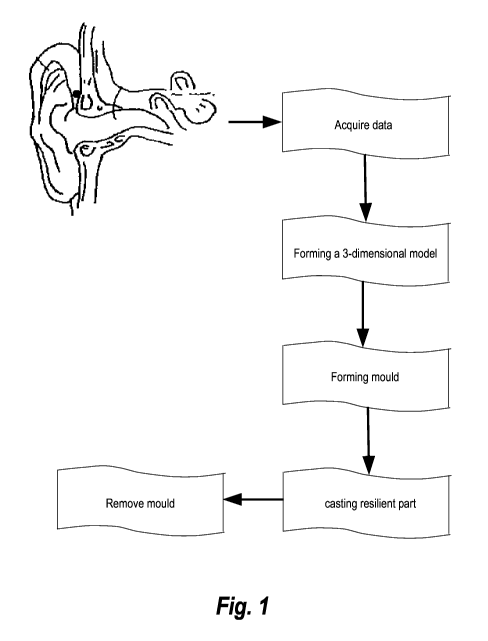
Fig. 1 illustrates schematically process steps in an embodiment of the
invention for manufacturing a resilient ear mould.
Fig. 2 illustrates two views of a prior art ear plug manufactured by a rapid
1o prototyping process.
Fig. 3 illustrates two views of a mould for casting a resilient ear plug.
Fig. 4 illustrates two views of an ear plug made in a resilient material.
Fig. 5,illustrates two views of an ear plug with a receiver.
Fig. 6 illustrates two views of a prior art shell of an in-the-ear hearing
aid.
Fig. 7 illustrates two views of the shell of Fig. 6 where a part has been
recessed.
Fig. 8 illustrates two views of a mould for casting a resilient part for the
shell in
fig. 7.
Fig. 9 illustrates two views of a resilient part cast in the mould of fig. 8.
CA 02740212 2011-04-11
52966-45
7
Fig. 10 illustrates two views of the shell of fig. 7 provided with a resilient
hearing aid part.
Detailed Description of Embodiments
An example of the method according to the invention is given in figure 1. Data
representing the shape of the auditory canal are acquired and stored in a
computer. These data can be acquired in several ways, e.g. by making an
impression of the ear of a hearing aid user including the auditory canal and
then scanning and digitizing the outer contour of this impression. Commercial
scanners are available for this- purpose. Data representing the shape of the
auditory canal may also be obtained by other means such as direct scanning of
the auditory canal by laser, X-rays, ultrasound etc. Three dimensional laser
scanners for this purpose are known.
Once the data representing the shape of the auditory canal have been stored in
a computer, these data can be applied for producing a three-dimensional
computer model of an ear plug or an in-the-ear hearing aid fitting the
auditory
canal of the hearing aid user. .
In a method according to the invention a mould for casting an ear plug is
established in the form of a three dimensional computer model. This mould is
designed to be manufactured in a rapid prototyping process, and the mould is
typically prepared for easy removal from the cast ear plug.
The mould is designed such that its inner dimensions will fit the wanted outer
dimensions of the cast ear plug. However, any predictable changes in material
dimensions, such as shrinkage, of the ear plug material during or after
casting
should be accounted for, i.e. the mould should be produced correspondingly
larger in order to take shrinkage into account, such that the size of the
finished
ear plug will fit the ear. Also when designing the mould, shrinkage of the
hard
material, such as acrylic or polyamide, applied for the mould should be taken
into account.
CA 02740212 2011-04-11
8
When manufacturing hollow hard ear plugs of e.g. acrylic by an SLA rapid
prototyping process the wall thickness of the shell is often selected to be in
the
range 0.4 - 0.8 mm, preferably about 0.7 mm. However, it has been found that
when applying the rapid prototyped mould for casting the ear plug in a
resilient
material, a wall thickness of the relatively hard material of 0.3 - 0.4 mm,
preferably 0.3 mm or less, has the advantage that this relatively hard
material is
easy to crush and remove from the finished resilient ear mold. Other methods
for removing the finished ear plug from the mould are also possible. This
could
1o e.g. be introduction of crack initiation lines in the mould along which
separation
into two or more parts would be easily accomplished. When applying an SLS
rapid prototyping process polyamide could be used instead of acrylic.
Traditionally, the material for a rapid prototyping process manufactured hard
ear plug is limited by the necessity of the material to be biocompatible,
meaning
that humans can tolerate exposure to specimens of the material in their
auditory canal for extended time periods without any harmful effect and
without
any undesired skin reactions, such as allergy, irritation or toxic reactions.
Biocompatibility is further defined in the standard ISO 10993. Acrylic has
often
been preferred for the purpose. However, when the rapid prototyping process
manufactured hard material is applied as a mould for casting, the hard
material
will not come into contact with the skin of the hearing aid user. Therefore,
other
materials, such as epoxy or other traditional materials for a rapid
prototyping
process could be used for forming the mould.
In general the resilient hearing aid component should be manufactured from a
biocompatible material, and this material should not absorb any compounds
from the harder mould material, which compounds could be releasable during
use of the hearing aid component.
CA 02740212 2011-04-11
9
A resilient material will be understood as being a material resuming its
original
shape after compression, i.e. energy may be absorbed when deforming the
material, and this energy is recovered when the deformation is removed.
Furthermore, the resilient hearing aid component should preferably be
manufactured from a material having a hardness which is below 80 measured
on the Shore durometer type A scale (see the standard ASTM D2240 for
description of the test). This is often written as Shore 80A. Preferably, the
hardness is below Shore 60A, and more preferably the hardness is in the range
from Shore 20A to Shore 45A.
One material in which the resilient hearing aid component could preferably be
manufactured is silicone. A preferred silicone is the Biopor, which is
biocompatible. However, other resilient materials, such as soft acrylic may
also
be applied. Preferably the material is injected into the finished mould. When
silicone is applied this may be in the form of a hot vulcanization silicone
which
often has to be vulcanized at a temperature of e.g. 220 C. The silicone may
also set by application of ultraviolet light. In a preferred embodiment the
silicone is in the form of a two component silicone where the two components
may be mixed in the injector just before injecting the material into the
mould.
After mixing the two components, the silicone will vulcanize or harden at room
temperature in approximately 20 minutes. A pressure may be applied while the
silicone is hardening. Such a pressure may have the advantage of increasing
the diffusion of air bubbles such that these are removed from the liquid
silicone.
Thereby the number of air bubbles in the finished hearing aid component can
be significantly reduced. An example of a pressure applied to the silicone in
the
mould is approximately 5 bar.
Other examples of materials which could be applied for the resilient hearing
aid
component are thermoplastic elastomers (TPE) and liquid silicone rubber
(LSR).
CA 02740212 2011-04-11
One advantage with the method according to the invention is that grinding of
the resilient hearing aid component in any form is usually not necessary. A
finished ear plug or hearing aid component may be lacquered with a layer of
e.g. vulcanizing lacquer. Different types of lacquer exist; these may provide
the
5 surface with different properties, such as a specific frictional
coefficient,
improved cleaning ability or improved resistance to microbiological growth.
Also, more than one layer of lacquer may be applied in order to obtain
specific
surface properties. However, many ear plugs manufactured according to the
method of the invention will be applied directly without any layer of lacquer.
The
10 hardened lacquer would also have to be biocompatible.
Often a manufactured ear plug will have to encase the receiver of the hearing
aid. Therefore, in this situation space for the receiver and preferably
holding
means for holding the receiver should be included in the manufacturing of the
ear mould. Such holding means should therefore also be part of the three
dimensional model of the ear plug. The holding means for holding the receiver
may also be a separate component adapted to the receiver and fitting into the
space in the earplug where the receiver is to be arranged.
The space for the receiver is designed with shape and dimensions such that
the specific receiver for the hearing aid selected for the hearing aid user
will fit
into the earplug. Furthermore, an open canal should connect the sound
generating part of the receiver with the part of the ear plug arranged to face
the
ear drum of the hearing aid user. There will thus be direct access for the
sound
from the receiver to the ear drum. Means for holding e.g. a grid for
preventing
earwax in getting into the receiver may also be arranged as part of the ear
plug.
In a number of situations the ear plug will extend not only in the ear canal
but
also in part of the concha. The receiver could e.g. be arranged in the part of
the
ear plug extending in the concha, where the space will be less limited
compared to the ear canal. This is especially the situation for children. When
CA 02740212 2011-04-11
11
the receiver is placed in the concha part of the ear plug, the canal conveying
sound from the receiver to the space in front of the ear drum may be bended.
Often the ear plug will have to be applied with a behind-the-ear hearing aid
where the receiver is arranged in the behind-the-ear part, and where a tube is
guiding the sound from the receiver to the ear plug and through the ear plug.
In
this case the ear plug will be provided with means for holding the tube.
In one embodiment according to the invention, the resilient hearing aid
component manufactured is a resilient ear plug. Figure 2 illustrates a prior
art
ear plug 5 manufactured by a rapid prototyping process. This ear plug is
manufactured in a relatively hard non-resilient material and will often be
ready
to use, maybe after grinding or polishing. This ear plug cannot be applied as
mould for a resilient earplug, partly because the outer dimensions of the
resilient ear plug will have to be equivalent with the outer dimensions of the
hard ear plug in figure 2, which is not possible if applying the hard ear plug
as
mould for the resilient ear plug. Also, the known ear plug 5 is usually
provided
with means for holding the receiver. However, it has been found that the
software for designing the hard ear plug can also be applied for designing the
mould for casting the resilient earplug.
Figure 3 illustrates such a mould 10 for casting a resilient ear plug in e.g.
silicone. The mould 10 has been modeled as a three dimensional model on a
computer and has been manufactured by a rapid prototyping process. The
mould 10 in this example comprises an outer shell 11 and an inner core 12.
The outer shell 11 will be applied for casting the earplug with an outer
surface.
The inner core 12 can be removed from the finished earplug, whereby a space
will be created inside the earplug into which the receiver can be inserted.
This
space may also be provided with means for holding the receiver and preferably
locking the receiver or a tube into the correct position. These holding means
can be in the form of a recess or an edge, fitting with corresponding means on
the receiver. The inner core 12 may be provided with any shape necessary for
CA 02740212 2011-04-11
12
fitting the shape of the receiver. When a ventilation canal is needed in the
ear
plug, a second inner core needs to be arranged as part of the mould. This
second inner core also has to be arranged inside the outer shell 11.
Figure 4 illustrates an ear plug 15 made in a resilient material cast in the
mould
in figure 3. The resilient material may be transparent or translucent or it
may be
opaque given any color. The cylindrical opening 16 extending from the back
end 17 to the front end 18 of the ear plug 15 is for placement of the
receiver. If
a canal for ventilation is needed, a further opening (not shown) from the back
end 17 to the front end 18 of the ear plug should be arranged.
In figure 5 the ear plug 15 of figure 4 has been mounted with a receiver which
has been arranged in the cylindrical opening 16. A first plug 21 is engaged in
a
socket (not shown) in contact with the receiver. This first plug 21 connects
the
receiver through a lead 22 to a second plug 23 adapted for engaging a socket
in a casing housing electronics of the hearing aid. This casing will typically
be
of the behind-the-ear type.
In an embodiment according to the invention a resilient hearing aid component,
being part of an in-the-ear hearing aid, is manufactured. Figure 6 illustrates
a
shell 30 of a known in-the-ear hearing aid with a hearing aid part 31 adapted
for
fitting closely into the ear canal of the hearing aid user. Such shells are
typically
made directly by a rapid prototyping process based on a three dimensional
computer model of the hearing aid user's ear and ear canal. Traditionally, the
hard material, e.g. acrylic, from which the shell is made, has been arranged
to
be in direct contact with the ear canal. However, with the method according to
the invention it is possible to manufacture a custom fitted hearing aid where
the
part in contact with the ear canal, can be manufactured from a resilient
material, thereby obtaining the advantage of such a material.
In order to manufacture such a hearing aid shell a two phase process is
preferred, where the hard part of the shell is manufactured in one phase and
CA 02740212 2011-04-11
13
the resilient hearing aid component is manufactured in a different phase. The
two parts are then integrated into the hearing aid shell.
Figure 7 illustrates a result of a phase manufacturing the hard part of the
shell.
In this phase a part 31 of the shell, arranged to be inserted deepest into the
ear
canal of the hearing aid user, has been contracted or recessed to exhibit a
reduced cross-section. This recessed part 35 is made when forming the three
dimensional computer model of the shape of the shell. The recessed part will
be covered in a way to be explained below by a covering in the form of a cup-
shaped sheath, covering or envelope of a resilient material. The hard part of
the shell could have a material thickness in the range 0.4 - 0.8 mm,
preferably
approximately 0.7 mm. This thickness will preferably also apply for the
recessed part 35. The distance of the recess is the step between the non-
recessed and the recessed part which equals the distance between the surface
of the hard material and the outer surface of the resilient hearing aid
component. The step therefore equals the thickness of the resilient part to be
placed around the recessed part. Two opposing needs should be balanced
when selecting this step. With a larger step more resilient material will be
present between the hard surface and the wall of the ear canal. This will make
the resilient hearing aid component more flexible. However, since the
dimensions of a hearing aid user's ear canal are approximately constant, a
larger step will lead to smaller dimensions and less space inside the hearing
aid shell. This may be a problem when arranging the placement of the receiver.
Often a step of the recess in the range 0.5 - 1 mm is preferred.
Figure 8 illustrates a mould 40 for casting a resilient hearing aid component
50
(see figure 9) which will fit the recessed shell part 35 in figure 7. The
mould 40
is designed by forming a three dimensional computer model of the hearing aid
shell 30 including the resilient component 50. During this modeling step the
shape and the dimensions of the resilient hearing aid component 50 will also
be
decided. Based on the shape and dimensions of the resilient hearing aid
component the mould 40 for casting the resilient hearing aid component 50 can
CA 02740212 2011-04-11
14
be formed as a three dimensional computer model. From this model the mould
40 is manufactured in a rapid prototyping process. The mould 40 will typically
comprise an outer layer 41 and an inner core 42 between which there is an
open space 45 in which the resilient hearing aid component 50 can be cast.
The dimensions of the inner core 42 equals the dimensions of the recessed
hard part 35 of the hearing aid shell.
Figure 9 illustrates a resilient hearing aid component 50 cast in the mould of
figure 8. The resilient component 50 in this embodiment is to some extent cup
shaped with a wall 55 having a thickness defining the thickness of the
resilient
layer, and an outer surface which, in the finished hearing aid component, will
be in contact with the ear canal of the hearing aid user. Furthermore, an
opening 56 is provided in the bottom of this cup shape. This opening 56 is
often
circular or substantially circular in shape, and has the purpose of allowing
sound from the receiver to reach the space between the part of the hearing aid
inserted in the ear canal and the ear drum. The opening 56 is made during
casting the resilient hearing aid component 50 by having means 46 for forming
the opening as part of the mould 40.
Figure 10 illustrates the shell 30 of figure 7 provided with the resilient
hearing
aid component 50 of figure 9. The resilient component could be glued or press
fitted to the hard recessed part 35 of the shell.
In a first example according to one embodiment of the invention an impression
(e.g. in silicone) is made of the hearing aid user's ear and ear canal. This
impression is scanned in a three dimensional scanner, thereby creating a set
of
data describing the shape of the auditory canal of the hearing aid user. These
data are applied in a software package for building a model of an ear plug for
a
behind-the-ear hearing aid. Based on this model, a model of the mould for
casting the hearing aid component is designed. This model will define the
outer
surface of the ear plug as well as the inner cavity for holding a receiver or
a
sound tube. Also any ventilation canal will be part of this design and must be
CA 02740212 2011-04-11
part of the mould. The mould is now manufactured by an SLA rapid prototyping
process. The mould is made in acrylic and the outer shell of the mould will be
made in a thickness of 0.3 mm, while the inner part for defining the cavity
for
the receiver is often solid. A two component silicone is now mixed and
injected
5 into the mould. The silicone is hardening at room temperature and at a
pressure of 5 bar for approximately 20 minutes. Following this the ear plug
can
be removed from the mould by crushing the outer shell of the mould and
drawing the inner part of the mould out of the ear plug, thereby leaving the
space in the ear plug for the receiver. Finally, the receiver can be mounted
in
10 the ear plug.
In a second example according to a second embodiment of the invention an
impression (e.g. in silicone) is made of the hearing aid user's ear and ear
canal.
This impression is scanned in a three dimensional scanner, thereby creating a
15 set of data describing the shape of the auditory canal of the hearing aid
user.
These data are applied in a software package for building a model of an in-the-
ear hearing aid. This model will comprise one hard part forming the shell of
the
hearing aid, and one resilient part to be arranged on the outside of the hard
part, where the resilient part is arranged such that it will be in touch with
the
wall of the hearing aid users ear canal. The hard part 30 of the shell is
manufactured in approximately 0.7 mm acrylic, directly by an SLA rapid
prototyping process. Based on the model of the resilient hearing aid component
50, a model of the mould 40 for casting the resilient component 50 is
designed.
The mould 40 is then manufactured by an SLA rapid prototyping process. The
mould is made in acrylic and the outer layer 41 is made in a thickness of
approximately 0.3 mm, while the inner core 42 for defining the inner
dimensions
of the resilient component will be made solid. The resilient hearing aid
component 50 is now cast in the mould, by mixing a two component silicone
and injecting this into the mould. The silicone sets at room temperature and
at
a pressure of 5 bar for approximately 20 minutes. Following this, first the
inner
core 42 of the mould is withdrawn, and then the outer layer 41 of the mould is
crushed. The resilient material is now arranged on the recessed part 35 of the
CA 02740212 2011-04-11
16
hard part 30 of the shell. The resilient material is fastened by glue to the
recessed part. The other components of the hearing aid such as the electronic
module, the battery compartment, the receiver and the microphone are
arranged in the shell, whereupon a cover is placed over the opening 32 of the
shell as shown in e.g. WO 98/47319. Thereby the hearing aid is finished.