Note: Descriptions are shown in the official language in which they were submitted.
CA 02740224 2011-04-11
BLOOD PRESSURE STABILIZATION SYSTEM
USING TRANSDERMAL STIMULATION
CROSS REFERENCE TO RELATED APPLICATIONS
[00011 The present application claims priority under Article 4 of the Paris
Convention
(and corresponding stipulations of other countries) based upon U.S.
Provisional Patent
Application Serial No. 60/998,979, filed on October 15, 2007. The entire
disclosure of
the aforesaid applications is incorporated herein by reference.
FIELD OF THE INVENTION
[00021 The present invention relates to an electric stimulation apparatus for
treating
hypotension and a method for treating hypotension, and more specifically
relates to an
electric stimulation apparatus and a method used for treating patients with
spinal cord
injury.
BACKGROUND OF THE INVENTION
[00031 Patients with spinal cord injury are known to have hypotension due to
autonomic dysreflexia caused by the damage to the spinal cord, which is an
autonomic
nerve pathway. The spinal cord is an important nerve pathway and its failure
due to, for
example, a trauma blocks the neural transmission channels, resulting in motor
paralysis,
sensory paralysis, autonomic disorder or the like in downstream from the
injury site. In
Japan, about 5,000 people suffer spinal cord injuries annually and most of
them occur in
the higher level, thus 68% of these patients, 35% of which require
vasopressor. develop
hypotension
[00041 For patients with spinal cord injury, hypotension is a serious
condition.
Particularly orthostatic hypotension causes a sudden fall in blood pressure
when the
patient stands up, or sits up from the supine position, resulting in
dizziness,
lightheadedness or in severe cases unconsciousness. In order to control
hypotension,
various drug treatments have been performed, but with great difficulties since
this type
of hypotension is caused by the autonomic dysreflexia.
1/17
CA 02740224 2011-04-11
[0005] On the other hand, it is empirically known that mechanical or
electrical
stimulation increases the blood pressure, but this phenomenon has not been
taken
advantage of in the hypotension treatment application.
[0006] Although there is a method for directly and electrically stimulating
the spinal
cord in order to prevent the blood pressure decrease during a surgery, this
method
requires an invasive procedure for positioning a catheter near the spinal cord
by a
surgical technique, adding undesirable burden to the patient's body. In
addition, this
method requires to keep the invasive catheter attached to the patient on the
daily basis,
compromising the quality of life (QOL) of the patient with spinal cord injury.
SUMMARY OF THE INVENTION
[0007] Considering the above situation, the purpose of the present invention
is to
provide an apparatus capable of preventing and treating orthostatic
hypotension with
electric stimulation using a non-invasive method.
[0008] In order to address the aforementioned problems, according to a first
principal
aspect of the present invention, there is provided an electric stimulation
apparatus for
treating hypotension, comprising: a blood pressure measuring means for
continuously
measuring a blood pressure of a subject; an electric current application means
for
intermittently applying an electric current with a predetermined frequency to
skin of the
subject to thereby stimulate the subject skin; and a control means for
controlling the
electric current application means so as to maintain the blood pressure at a
predetermined
target blood pressure value by activating the electric current application
means to
stimulate the subject skin when the subject blood pressure is equal to or less
than the
target blood pressure value.
[0009] According to such a structure, a decrease in blood pressure may be
prevented
using a non-invasive method in which an electric current is applied to the
patient skin. In
other words, the present inventors found that the electric stimulation applied
to the skin
may provide a stable blood pressure increase response. Also, since these
response
characteristics are generally consistent for any patient, an apparatus can be
made with a
relatively simple structure capable of stabilizing the patient blood pressure
using, for
example, a feedback control.
2/17
CA 02740224 2011-04-11
[0010] According to one embodiment of the present invention, the electric
current
intermittently applied by the electric current application means has an
application period
shorter than a non-application period, and it is preferred that the
application period is 1-3
seconds and the non-application period is 4-10 seconds.
[0011] By applying such an intermittent electric current, stable effect of
blood pressure
increase may be provided continuously over an extended period.
[0012] According to another embodiment of the present invention, the electric
current
application means comprises an electrode positioned within inguinal, femoral,
lumbar
and lower abdominal regions of the subject.
[0013] According to such a structure, a maximum effect may be achieved with
minimum electric power or amperage.
[0014] According to yet another embodiment, the control means maintains the
blood
pressure of the subject at the target blood pressure value with a feedback
control. In this
case, the control means preferably controls the applied electric current at a
predetermined
frequency.
[0015] According to still another embodiment, this apparatus preferably
further
comprises an operation means for entering the target blood pressure value. In
addition,
the electric stimulation apparatus is preferably secured to a wheelchair.
[0016] According to a second principal aspect of the present invention, there
is
provided an electric stimulation method for treating hypotension, comprising
the steps
of. continuously measuring a blood pressure of a subject; intermittently
applying an
electric current with a predetermined frequency to skin of the subject to
thereby stimulate
the subject skin; and controlling an electric current application means so as
to maintain
the blood pressure at a predetermined target blood pressure value by
activating the
electric current application means to stimulate the subject skin when the
subject blood
pressure is equal to or less than the target blood pressure value.
[0017] The above and other characteristics of the present invention will be
readily
appreciated by those skilled in the art by referring to the following Detailed
Description
of the Preferred Embodiments and the accompanying drawings.
3/17
CA 02740224 2011-04-11
BRIEF DESCRIPTION OF THE DRAWINGS
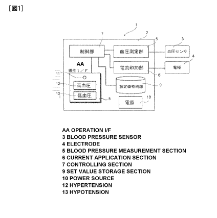
[0018] Fig. 1 is a schematic structural view showing an electric stimulation
apparatus
of the present invention;
[0019] Fig. 2 is a graph showing changes in (a) heart rate and (b) blood
pressure
measured when (c) bed inclination angle is changed for a patient with
orthostatic
hypotension in the supine position;
[0020] Fig. 3A is a graph showing the systolic blood pressure change for
patients with
severe hypotension due to cervical and thoracic spinal cord injuries (10
patients with
various injury levels in C4A-C5A), wherein the each patient in the supine
position on a
tilt table was raised to a 30 degree and to a 60 degree angle;
[0021] Fig. 3B is a graph showing the mean blood pressure change for patients
with
severe hypotension due to cervical and thoracic spinal cord injuries (10
patients with
various injury levels in C4A-C5A), wherein the each patient in the supine
position on a
tilt table was raised to a 30 degree and to a 60 degree angle;
[0022] Fig. 4A is a graph showing the observed blood pressure change due to
the
stimulus applied to a patient, wherein each of the inguinal, femoral, lower
leg, near
umbilicus and subclavian regions of the patient was stimulated by pinching;
[0023] Fig. 4B is a graph showing the observed systolic blood pressure change
due to
the stimulus applied to a patient, wherein each of the lower leg, knee,
femoral, inguinal,
abdominal and subclavian regions of four patients was stimulated by pinching;
[0024] Fig. 5A is a diagram showing the heart rate and blood pressure change
measured when intermittent electric stimulation was applied within the lumbar
(1) and
lower leg (6) regions of the patient, where in the stimulation had settings of
40 mA, 40
Hz and 0.3 msec and intervals of 2 sec. ON and 6 sec. OFF;
[0025] Fig. 5B is a diagram showing the mean blood pressure increase measured
when
electric stimulation of 5 mA/cm2, 10 Hz, 0.3 msec was applied to each of the
lower leg,
femoral, inguinal and lower abdominal regions of patients;
[0026] Fig. 6A is a graph showing the blood pressure change observed
continuously
when attaching an electrode 4 to the patient inguinal region; and applying the
electric
4/17
CA 02740224 2011-04-11
current with a constant frequency at 10 Hz, square wave stimulations of 0.3
msec
interval and different amperage values 10 mA, 20mA, 40mA and 60mA;
[0027] Fig. 6B is a graph showing the changes in systolic blood pressure
(SBP), mean
blood pressure (MBP) and diastolic blood pressure (DBP) measured when an
electrode 4
was attached to the patient inguinal region; and an electric current was
applied with a
constant frequency at 10 Hz, square wave stimulations of 0.3 msec interval and
different
current values 1.3 mA/cm2, 2.5 mA/cm2, 5 mA/cm2 and 7.5mA/cm2;
[0028] Fig. 7A is a graph showing the blood pressure change measured when an
electric current was applied with a constant amperage 40 mA, square wave
stimulations
of 0.3 msec interval and varying the frequency from 0 Hz to 10 Hz;
[0029] Fig. 7B is a graph showing the changes in systolic blood pressure
(SBP), mean
blood pressure (MBP) and diastolic blood pressure (DBP) measured when an
electric
current was applied with a constant amperage 40 mA, square wave stimulations
of 0.3
msec interval and different frequencies of 5 Hz, 10 Hz, 20 Hz and 40 Hz;
[0030] Fig. 8 is a graph showing the blood pressure increase in response to
the electric
current applied to a patient with various intermittent time intervals
(continuous; 2 sec.
ON and 2 sec. OFF; 2 sec. ON and 4 sec. OFF; 2 sec. ON and 6 sec. OFF; and 2
sec. and
sec. OFF);
[0031] Fig. 9A is a diagram showing electric current-blood pressure dynamic
characteristics measured when an electric current with a constant frequency
was applied
to patients;
[0032] Fig. 9B is a diagram showing electric current-blood pressure dynamic
characteristics measured when an electric current with a constant frequency
was applied
to patients;
[0033] Fig. 10 are a block schematic diagram for designing a feedback-based
controller (a); and a graph showing the response characteristics for different
sets of the
coefficients Kp and Ki (b);
[0034] Fig. 11 shows the results of the blood pressure change in an actual
study
patient, wherein the varying electric stimulation was applied to the patient
under the
condition that the maximum amperage was 60 mA, target blood pressure value
5/17
CA 02740224 2011-04-11
85mmHg, frequency 10 Hz, stimulation interval 0.3 msec, 2 sec. on / 6 sec.
off, and
electrode area 8 cm2;
[0035] Fig. 12 is a graph showing the blood pressure change measured when the
target
blood pressure value was set to 85 mmHg, the frequency was kept constant and
the
electric current (amperage) was controlled;
[0036] Fig. 13 is a graph showing the blood pressure change measured when the
target
blood pressure value was set to 65 mmHg, the electric current (amperage) was
kept
constant and the frequency was controlled; and
[0037] Fig. 14 is a diagram showing the average blood pressure change for 7
cases
when the frequency was kept constant at 10 Hz, the maximum electric current
(amperage) was set to 60 mA, and the current was controlled.
DETAILED DESCRIPTION OF THE INVENTION
[0038] One preferred embodiment of the present invention will be described in
detail
below.
[0039] Fig. 1 is a schematic structural view illustrating an electric
stimulation
apparatus 1 according to this embodiment.
[0040] This apparatus 1 is defined by an apparatus main body 2 connected to a
blood
pressure sensor 3 and an electrode 4. The apparatus main body 2 is provided
with a blood
pressure measuring section 5, an electric current application section 6, a
control section
7, an interface 8, a set value storage section 9 and a power source 10.
[0041] The electric current application section 6 is connected to the
electrode 4 and has
a function to intermittently apply an electric current with a predetermined
frequency to
human skin through the electrode 4. The electrode 4 has an area of about 5 cm2
to 10 cm2
for applying the effective electric current and is preferably placed on the
patient skin
within the inguinal, femoral, lumbar and lower abdominal regions.
[0042] Also the blood pressure measuring section 5 has a function to
continuously
measure the patient blood pressure with the blood pressure sensor 3. This
blood pressure
sensor 3 may be an existing one and may be a non-invasive sensor, for example,
an
6/17
CA 02740224 2011-04-11
optical sensor or a wired/wireless blood pressure sensor using techniques such
as the
pulse wave velocity measurement method.
[0043] The control section 7 has a function to activate the electric current
application
section 6 to stimulate the patient skin when the patient blood pressure is
equal to or less
than a predetermined target blood pressure value, and control the electric
current
application section 6 so as to maintain the blood pressure at (or greater
than) the target
blood pressure value. This control section 7 is adapted to dynamically control
the electric
current applied to the electrode 4 using a feedback control as discussed
below.
[0044] The interface 8 is for setting the target blood pressure value and has,
for
example, a pilot lamp (indicator light) 11, a high blood pressure button 12
and a low
blood pressure button 13 so as to configure a standard target blood pressure
value and
other target blood pressure values corresponding to each of these buttons, as
shown in
Fig. 1. In addition, this operation interface 8 may be provided with a digital
blood
pressure display section (not shown) for displaying the target blood pressure
value and/or
measurements or, for example, a up and down buttons for performing fine
adjustments.
[0045] The set value storage section 9 stores the target blood pressure value
configured
at the operation interface 8; an amperage, a frequency and other operational
characteristics of the electrode 4; measurement characteristics of the blood
pressure
sensor 3; and other settings. These settings are adapted to be retrieval by
the control
section 7 and used for the feedback control. This set value storage section 9
also stores a
time interval for activating the electrode 4 (or electric current application
section 6). As
will be described below, the electrode activation is intermittent and the time
intervals are
preferably configured so that the current is applied for a range of 1-3
seconds and
stopped for a range of 4-10 seconds.
[0046] Configuration and operation of this apparatus and an exemplary method
for
treating hypotension using this apparatus will be described in detail below.
[0047] Blood Pressure Change in Patients with Cervical Spinal Cord Injury
[0048] Fig. 2 is a graph describing orthostatic hypotension treated with the
apparatus
according to the present embodiment. In this figure, (a) is the patient heart
rate; (b) is the
patient blood pressure; and (c) is bed inclination angle for a patient with
severe
7/17
CA 02740224 2011-04-11
hypotension. As shown in (b), the blood pressure decreases significantly as
the bed
inclination angle increases from 0 degree to 60 degree.
[0049] Figs. 3A and 3B are graphs showing the blood pressure change for
patients
with severe hypotension due to cervical and thoracic spinal cord injuries (10
patients
with various injury levels in C4A-C5A). In both graphs, each patient in the
supine
position on a tilt table was raised to a 30 degree and to a 60 degree angle
and his or her
electrocardiogram and blood pressure were continuously recorded to measure the
decrease in blood pressure. As a result, blood pressure decreases correlated
to the bed
inclination angle were observed for all of the patients.
[0050] The apparatus and method of the present embodiment prevent the
orthostatic
blood pressure decline in such patients with orthostatic hypotension due to
spinal cord
injury.
[0051] Electrode Positioning
[0052] Figs. 4 and 5 are various graphs showing an optimal position to attach
the
electrode 4.
[0053] In this embodiment, in order to first identify the optimal attachment
position,
each of the lower leg, knee, femoral, inguinal, lower abdominal and subclavian
regions
of patients was stimulated by pinching, and the blood pressure increase due to
the
stimulus was observed, as shown in Figs. 4A and 4B. An electrode 4 was
attached to
each of the identified sites of the patient body and the elevation in systolic
and average
blood pressures were determined for the each site, resulting in relatively
higher responses
in the femoral, inguinal and lower abdominal regions, as shown in Figs. 5A and
5B.
[0054] As can be seen from these results, the optimal position to attach the
electrode 4
is within the inguinal, femoral and lower abdominal regions although the
electrode 4
may be attached to sites other than those identified as above depending on the
patient
body position or other reasons. Although the above results merely indicate the
specific
electrode attachment positions, the electrode may be attached to other sites
such as
lumbar region within the inguinal, femoral and lower abdominal regions. If the
characteristics of the blood pressure increase response vary depending on the
electrode
attachment position, electrode characteristics may be adjusted accordingly in
the set
8/17
CA 02740224 2011-04-11
value storage section 9 and the electrode may be attached to the lower leg
region or
upper body as well.
[0055] Electric Current and Frequency Setting
[0056] The present apparatus may start its operation after the electrode 4 and
blood
pressure sensor 3 are attached to the patient skin and the power source 10 is
connected.
During its operation, when the patient blood pressure falls equal to or under
the
predetermined target value, it compensates the blood pressure decrease by
applying an
electric current with the predetermined frequency and amperage to the patient
skin via
the electrode 4.
[0057] The results are shown below. The electrode 4 was attached to a
desirable
position within the inguinal and lower abdominal regions which had been
identified to
produce high responses in the above electrode positioning experiment. Figs. 6A
and 6B
are graphs showing the results of the blood pressure change obtained by
attaching the
electrode 4 to the desirable position within the inguinal and lower abdominal
regions of
the patient; and applying the electric current with a constant frequency at 10
Hz, square
wave stimulations of 0.3 msec interval and varying amperage 0-7.5 mA/cm2 with
0.5
mA/cm2 steps. These graphs indicated that the patient blood pressure responded
to the
applied electric current and increased at any amperage and the responses
positively
correlated with the increase of the electric current. It should be noted that
patients with
spinal cord injury do not feel pain, and therefore it is possible and
effective to raise the
amperage of the applied electric current to an extent which does not damage
the patient
skin.
[0058] Figs. 7A and 7B are graphs showing the results of the blood pressure
change
obtained by attaching the electrode 4 to the desirable position within the
inguinal and
lower abdominal regions of the patient; and applying the electric current with
a constant
amperage 40 mA, square wave stimulations of 0.3 msec interval and different
frequencies of 5 Hz, 10 Hz, 20 Hz and 40 Hz. These graphs indicate that the
patient
blood pressure responded to all of the frequencies of the applied electric
current and the
responses positively correlated with the frequency increase. At higher
frequencies,
however, patients experience discomfort due to the tonic muscle contraction
and it is
preferable to apply relatively lower frequencies and increase the electric
current
9/17
CA 02740224 2011-04-11
(amperage). For example, the muscle contraction discomfort caused at
frequencies of
about 10 Hz or higher is significant, but that caused below 10 Hz is
considered small.
[0059] Electrode Size Setting
[0060] In this embodiment, the blood pressure change was examined in relation
to
different sizes of the electrode 4 in order to determine the size of the
electrode 4 for
optimal electric stimulation. As previously discussed, the electric
stimulation was
applied through the electrode attached to the inguinal region of the patients.
As a result,
the response increased with relatively smaller electrodes and with a plurality
of
electrodes rather than one. This suggests that the electric current density at
the skin
stimulation position governs the blood pressure response. This finding, in
comparison
with previous study reports, may be taken advantage of to achieve higher blood
pressure
responses with lower electric stimulation
[0061] According to this result, the optimal electrode size was determined to
be 5 cm2-
cm2 in this embodiment, but sizes smaller or larger than this range may also
be used,
needless to say.
[00621 In addition, the number of the electrode is not limited to one and a
plurality of
electrodes may be used. In that case, the same or different sizes may be used
for the
plurality of electrodes. For example, when using two electrodes, they are
preferably
placed within the same region of the patient body at bilaterally symmetrical
positions.
[0063] Intermittent Stimulation Conditions
[0064] As previously discussed, the present embodiment intermittently applies
the
electric current to the patient.
[0065] This intermittency is based on the fact that the blood pressure
response declines
to no effect in several minutes when the electric current stimulation is
continuously
applied to the patient skin. Fig. 8 is a graph showing the blood pressure
increase response
observed when the electrode 4 was attached to the desirable position within
the patient's
inguinal and lower abdominal regions and the electric current was applied with
various
intermittent time intervals (continuous; 2 sec. ON and 2 sec. OFF; 2 sec. ON
and 4 sec.
OFF; 2 sec. ON and 6 sec. OFF; and 2 sec. and 10 sec. OFF) in order to
determine an
appropriate time interval for the intermittent stimulation. As shown in Fig.
8, during the
10/17
CA 02740224 2011-04-11
continuous stimulation, a tendency of gradual decrease in blood pressure was
observed.
It is effective to provide a non-stimulating interval (OFF period) longer than
a
stimulating interval, wherein an appropriate OFF period length needs to be
evaluated
since the blood pressure starts declining during prolonged non-stimulation. As
optimal
intermittent conditions, the stimulating interval is 1-3 sec. and non-
stimulating interval 4-
sec., and most preferably, the stimulating interval is 2 sec. and non-
stimulating
interval 6 sec.
[0066] Feedback Control
[0067] As discussed above, the.control section prevents the patient blood
pressure
decrease and performs the feedback control to stabilize the blood pressure at
the target
value. In order to configure this feedback control, electric current-blood
pressure
dynamic characteristics were examined, as shown in Figs. 9A and 9B. From these
results, generally common dynamic characteristics were found regardless of the
severity
of patient injury. These results indicate that the blood pressure decrease may
be
controlled by performing a certain electric control for any subject of
treatment.
[0068] In order to estimate the transfer function and design a controller
based on the
above identified dynamic characteristics, the blood pressure dynamic response
against
the electric skin stimulation was identified using the white noise method or
the step
response, and an exemplary feedback-based controller was designed as shown in
the
block schematic diagram of Fig. I OA. Fig. I OB is a graph showing the
response
characteristics for different sets of the coefficients Kp and Ki. Although the
example of
Fig. 10 used the PID control scheme, the present invention is not limited to
this scheme.
[0069] It should be noted that, when a plurality of electrodes are used, this
control
section may be provided depending on specific needs of the respective
electrodes
(electric current application sections), or a single control section may be
control the
plurality of electrodes.
[0070] Operational Examples
[0071] Fig. 11 shows the results of the blood pressure change in an actual
study
patient, wherein the varying electric stimulation was applied to the patient
under the
condition that the maximum amperage was 60 mA, target blood pressure value
11/17
CA 02740224 2011-04-11
85mmHg, frequency 10 Hz, stimulation interval 0.3 msec, 2 sec. on / 6 sec.
off, and
electrode area 8 cm2. As evidenced by this figure, the blood pressure of the
treated
patient was maintained at the target blood pressure value of 85 mmHg by the
intermittently applied electric stimulation.
[0072] Also as another example of using the same apparatus, Fig. 12 shows the
blood
pressure change when the target blood pressure value was set to 85 mmHg, the
frequency
was kept constant and the electric current (amperage) was controlled. As a
further
example of using the same apparatus, Fig. 13 shows the blood pressure change
when the
target blood pressure value was set to 65 mmHg, the electric current
(amperage) was
kept constant and the frequency was controlled.
[0073] Thus, according to the apparatus of the present embodiment, the patient
blood
pressure may be stabilized at the target blood pressure value in a short
period of time
regardless of the severity of patient injury or other attributes by simply
setting the target
blood pressure value. In this embodiment, for example, the patient blood
pressure can be
increased to and maintained at the target blood pressure value within about 20
seconds.
[0074] Moreover, Fig. 14 shows the average blood pressure change for 7 cases
when
the frequency was kept constant at 10 Hz, the maximum electric current
(amperage) was
set to 60 mA, and the current was controlled. In any of these cases, sustained
blood
pressure increase was observed with application of the intermittent electric
stimulation
and the blood pressure was found to be maintained near the target blood
pressure value.
[0075] Apparatus Usage Example
[0076] Although the above described the case of patients in bed raised from
the supine
position, in the most typical usage example, the present apparatus may be
secured to a
wheelchair and attached to the patient in the wheelchair.
[0077] While the invention has been described, the present invention is not
limited to
the aforesaid examples and various changes and modifications can be made
without
departing from the spirit and scope of the invention.
[0078] For example, hypotension cases due to spinal cord injury have been
discussed
in the above embodiment, but the application of the present apparatus is not
limited to
12/17
CA 02740224 2011-04-11
hypotension and may also be applied to patients with systolic blood pressure
lower than
100 mmHg.
[0079] In addition, the above one embodiment is provided with various
components in
the apparatus main body 2, but not limited to such a implementation and may be
composed of a plurality of cases.
13/17