Note: Descriptions are shown in the official language in which they were submitted.
CA 02740563 2011-04-14
WO 2010/057309 PCT/CA2009/001681
1
TITLE OF THE INVENTION: REMOVABLE SEATS SYSTEM
CROSS-REFERENCE DATA
The present patent application claims priority under the Paris Convention of
United States provisional patent application No. 61/199,969 filed on November
21, 2008.
FIELD OF THE INVENTION
The present invention relates to a removable seats system, and more
particularly to a removable seats system for use in a multipurpose room.
BACKGROUND OF THE INVENTION
It is known to provide removable seats in multipurpose rooms. For example,
some rooms are used both in a theatre room configuration wherein rows of seats
that are
releasably fixed to the ground are provided, and in a free floor room
configuration wherein
the seats are removed to allow the floor to be used differently for trade
shows, conferences,
dinners, stage extensions (see figure 2 of the annexed drawings for example)
or the like. To
accommodate such a hybrid room, a removable seats system can be incorporated
into the
room to allow the seats to be removed and installed according to the daily
purpose of the
room.
In theatre room configuration, fixed seats are preferable over loose seats
that
may move over ground for numerous reasons, including the fact that loose seats
can be
noisy during theatre room shows. Consequently, it is desirable for
multipurpose rooms to
have their removable seats be releasably fixed to the ground when in their
theatre room
configuration. Furthermore, it is preferable that the fixed seats be easy to
stow when they are
removed, for example in the multipurpose room itself. It has been found that
stowing the
seats underneath floor platforms is both easy and practical, since the seats
remain readily
accessible for installation while being concealed when not in use.
It is also desirable for the multipurpose rooms to have a segmented floor
comprising a number of vertically movable platforms to configure the floor
either in a
gradually ascendant configuration away from the theatre scene when in theatre
room
configuration, or in a flat floor configuration when in free floor
configuration.
One challenge in having movable floor platforms is to have the floor remain
very stable when attendees walk on it, both in theatre room configuration and
in free floor
CA 02740563 2011-04-14
WO 2010/057309 PCT/CA2009/001681
2
configuration. Indeed, even very small movements of the floor can be detected
by attendees
and these can be disturbing. Likewise, the seats must also be very stable when
installed in
theatre room configuration. Again, very small movements of the seats are
disturbing for
those seated on them.
Some prior art multipurpose rooms propose removable seats systems wherein
seats are stowed underneath the floor platforms when they are not required,
while being
raised or installed on the floor when the theatre room configuration is
required. However,
the prior art systems fail to properly address the problem of both the floor
platforms and the
seats being stable and unmoving while providing a simple and practical
removable seats
system by which it is easy to install and remove the seats. To address the
practicality issue,
some prior art systems propose automated systems wherein the seats may be
moved from
underneath the floor platforms to an operative position above. Notwithstanding
very
complex, expensive or impractical prior art solutions, one particular problem
with some
prior art systems is that the floor platforms are either significantly spaced
apart, which yields
possible movement of the platforms and/or aesthetically undesirable results
and/or gaps that
can be accidentally engaged by high heels; or provided with non-trivial
openings in the
platforms themselves that allow the seats to be raised into their operative
position which
structurally weakens the platforms. These solutions make for unstable floors
even once the
seats are entirely installed or removed, which is disturbing for the attendees
that walk on
them. Most prior systems also provide seats that engage the floor platforms in
an unstable
manner, which yields seats that are allowed to move and again this is
disturbing for the
persons sitting on the seats.
SUMMARY OF THE INVENTION
The present invention relates to a removable seats system comprising:
- a first vertically movable platform defining opposite upper and
lower sides;
- a seat member comprising at least one seat; and
- first and second complementary male-female engagement members
respectively
provided on said first platform and on said seat member;
wherein said seat member may be removably installed in an operative position
on said upper
side of said first platform through a releasable engagement of said first and
second male-
female engagement members with one another.
CA 02740563 2011-04-14
WO 2010/057309 PCT/CA2009/001681
3
In one embodiment, said first and second male-female engagement members
respectively comprise first and second complementary male-female wedge
members,
whereby said seat member may be removably installed in said operative position
on said
upper side of said first platform through the releasable engagement of said
first and second
male-female wedge members with one another in a wedging relationship.
In one embodiment, one of said first and second male-female wedge members
comprises a pin member having a tapering outer wall and the other of said
first and second
male-female wedge members comprises a socket having a tapering bore for
receiving said
pin member in releasable wedging relationship.
1 o In one embodiment, said seat member comprises a number of pin
members
having a tapering outer wall and said platform comprises a number of sockets
having a
tapering bore, each said socket capable of receiving one of said pin members
in releasable
wedging relationship.
In one embodiment, each said socket comprises a cap movable between an
opened position in which access to said tapering bore is allowed and a closed
position in
which it covers said tapering bore, whereby one of said pin members may be
received in a
corresponding said socket when said socket cap is in said opened position.
In one embodiment, the removable seats system further comprises a second
platform defining upper and lower sides and which is horizontally adjacent and
vertically
movable with respect to said first platform, and a seat stowing structure
installed on said
lower side of said second platform wherein said seat member may be stowed on
said
stowing structure in a stowed position when it is not in said operative
position.
In one embodiment, the removable seats system further comprises a first
horizontal seat displacer provided on said second platform and capable of
moving said seat
member along a horizontal direction, wherein through the combined vertical
relative
movement of said first and second platforms and horizontal movement of said
first
horizontal seat displacer, said seat member can be moved between said stowed
position and
said operative position.
In one embodiment, said first horizontal seat displacer comprises a first rail
member on which a first carriage is movable and a first carriage actuator
capable of moving
said first carriage along said horizontal direction, whereby said seat member
resting on said
carriage may be moved along said horizontal direction.
CA 02740563 2011-04-14
WO 2010/057309 PCT/CA2009/001681
4
In one embodiment, the removable seats system further comprises a second
horizontal seat displacer comprising a second rail member on which a second
carriage is
movable and a second carriage actuator capable of moving said second carriage
along said
horizontal direction, whereby said seat member resting on said first and
second carriage may
be moved along said horizontal direction.
In one embodiment, the removable seats system further comprises a
releasable locking mechanism for releasably locking said first and second male-
female
engagement members with one another.
The present invention further relates to a method of removably installing a
seat member having at least one seat in an operative position on a first
platform having
upper and lower sides, comprising the steps of:
- providing first and second complementary male-female engagement
members
respectively on said first platform and on said seat member; and
- moving said seat member spacedly over and relative to said first
platform upper side
until said first and second male-female engagement members releasably engage
one another,
said first platform thereby supporting said seat member through the inter-
engagement of said
first and second male-female engagement members.
In one embodiment, the step of moving said seat member spacedly over and
relative to said first platform upper side until said first and second male-
female engagement
members releasably engage one another comprises the following steps:
- positioning said seat member spacedly over said first platform upper
side for said
first and second male-female engagement members to become aligned with one
another; and
- lowering said seat member relative to said first platform upper side
until said first
and second male-female engagement members releasably engage one another, said
first
platform thereby supporting said seat member through the inter-engagement of
said first and
second male-female engagement members.
In one embodiment, the step of providing first and second complementary
male-female engagement members respectively on said first platform upper side
and on said
seat member comprises providing complementary first and second male-female
wedge
members respectively on said first platform and on said seat member whereby in
the step of
lowering said seat member relative to said first platform upper side until
said first and
second male-female engagement members releasably engage one another, said
first and
second male-female wedge members releasably engage one another in wedging
relationship.
CA 02740563 2011-04-14
WO 2010/057309 PCT/CA2009/001681
In one embodiment, the step of providing first and second male-female wedge
members respectively on said first platform upper side and on said seat member
comprises
providing pin members having a tapering outer wall on said seat members and
sockets
having a tapering bore on said platforms whereby in the step of lowering said
seat member
5 relative to said first platform upper side until said first and second
male-female wedge
members releasably engage one another, said pin members are received in said
socket bores
in releasable wedging relationship.
In one embodiment, the method further comprises the following steps:
providing caps covering said sockets tapering bores; and
- before the step of lowering said seat member relative to said first
platform upper side
until said first and second male-female wedge members releasably engage one
another,
moving said caps towards an opened position in which access to said tapering
bores is
allowed.
In one embodiment, the method further comprises the following steps:
- providing a second platform having upper and lower sides and which is
horizontally
adjacent and vertically movable with respect to said first platform, said
second platform
comprising a seat stowing structure installed on its lower side; and
before the step of positioning said seat member spacedly over said first
platform
upper side for said second male-female engagement members to become aligned
with said
first male-female engagement members, providing said seat member on said
stowing
structures in a stowed position.
In one embodiment, the method further comprises the step of providing a
horizontal seat displacer on said second platform capable of moving said seat
member along
a horizontal direction, wherein the step of positioning said seat member
spacedly over said
first platform upper side for said second male-female engagement members to
become
aligned with said first male-female engagement members is accomplished by
relatively
positioning said first and second platforms vertically to have said seat
member vertically
clear said first platform above said first platform upper side when it is in
said stowed
position and by thereafter moving said seat member along said horizontal
direction by
means of said horizontal seat displacer, and wherein the step of lowering said
seat member
relative to said first platform upper side until said first and second male-
female engagement
members releasably engage one another is accomplished by vertically moving
said first and
second platforms with respect to one another.
CA 02740563 2011-04-14
WO 2010/057309 PCT/CA2009/001681
6
In one embodiment, said horizontal seat displacer comprises a rail member on
which a carriage is movable and a carriage actuator capable of moving said
carriage along
said horizontal direction, with said seat member resting on said carriage when
in said stowed
position, the step of moving said seat member along said horizontal direction
by means of
said horizontal seat displacer comprising moving said carriage along said
horizontal
direction while said seat member rests on said carriage.
In one embodiment, the step of providing first and second complementary
male-female engagement members respectively on said first platform upper side
and on said
seat member comprises providing complementary first and second male-female
wedge
members respectively on said first platform and on said seat member whereby
the step of
lowering said seat member relative to said first platform upper side until
said first and
second male-female engagement members releasably engage one another is
accomplished
by vertically moving said first and second platforms with respect to one
another until said
first and second male-female wedge members releasably engage one another in
wedging
relationship.
In one embodiment, the method further comprises the following step during
or after the step of lowering said seat member relative to said first platform
upper side until
said first and second male-female engagement members releasably engage one
another:
- releasably locking said first and second engagement members to one
another.
DESCRIPTION OF THE DRAWINGS
In the annexed drawings:
Figure 1 is a schematic top plan view of a multipurpose room equipped with a
removable seats system according to the present invention, showing a speaker
using the
room and with the room in its theatre room configuration;
Figure 2 is a partial schematic side elevation, at an enlarged scale, of the
room of figure 1, with the platform lifting mechanisms being omitted and
showing a few
attendees and a speaker using the room;
Figure 3 is a perspective view of a pair of platforms and one seat member of
the removable seats system of the present invention with the seat member in
its stowed
position;
CA 02740563 2011-04-14
WO 2010/057309 PCT/CA2009/001681
7
Figure 3A is similar to figure 3, but shows the seat member removed from its
stowed position;
Figure 4 is an enlarged perspective view of the area circumscribed by line IV
in figure 3;
Figure 5 is a cross-sectional side elevation, at an enlarged scale, of the
removable seats system of figure 3 with the bottom portion of the platform
actuators being
removed;
Figure 6 is an enlarged perspective view of a seat displacer of the removable
seats system of figure 3, also showing the adjacent portions of the platforms;
Figure 7 is a perspective view of a socket of the removable seats system;
Figures 8 and 9 are cross-sectional side elevations of the socket of figure 7
sequentially showing the socket cap in closed and opened positions, with
figure 9 further
showing a seat member pin member overhanging the socket;
Figures 10-15 are cross-sectional side elevations of the removable seats
is system of figure 3, taken from the opposite side, with the bottom
portion of the platform
actuators being removed, sequentially showing how a seat member may be
installed in its
operative position on a first platform from its stowed position under a second
platform;
Figure 16 is a view similar to figure 10, but showing how a seat member to be
installed on a rearmost platform may be stowed in a niche in a fixed
structure; and
Figures 17-20 are perspective views, at an enlarged scale, of a seat member
pin member engaging a platform socket that sequentially show how the seat
member
carriage may retrieve the seat member to disengage the pin member from the
socket when
the seat member is moved away from its operative position towards its stowed
position.
DETAILED DESCRIPTION OF THE EMBODIMENTS
Figures 1 and 2 schematically show a multipurpose room 40 which can be
configured either in a theatre room configuration to accommodate a seated
attendance (as
illustrated in figures 1-2) or alternately in a free floor configuration
(figure 10) wherein all
theatre seats are stowed away to allow the room to be used for dinners, shows
or any other
desired event wherein the theatre seats are not required.
Room 40 comprises a front stage portion 42 and a main room portion 44
which is provided with a removable seats system 46 according to the present
invention. As
CA 02740563 2011-04-14
WO 2010/057309 PCT/CA2009/001681
8
will be detailed hereinafter, removable seats system 46 comprises a number of
vertically
movable platforms 48 which collectively form a floor for people in main room
portion 44.
Platforms 48 can be installed at selected elevations and a number of seat
members 50 can be
selectively installed on the platforms. If seat members 50 are installed on
platforms 48, then
room 40 is said to be in its theatre room configuration wherein attendees may
be seated on
seat members 50. If seat members 50 are removed from the platforms and stowed
under
platforms 48 as detailed hereinafter, then room 40 is said to be in its free
floor configuration
and may then be used to receive a standing attendance or to install tables and
chairs on the
floor formed by the platforms 48, or for any other desired purpose wherein
seat members 50
1 o are not required.
Each seat member 50 includes a number of seats 82. For example, one seat
member 50 of removable seats system 46 shown in figure 1 may include a single
seat, an
entire row of seats or a fraction of a row of seats including several seats.
It is shown in
figure 1 that the rows of seats are arcuate; removable seats system 46 is
designed to
accommodate not only arcuate rows of seats, but also straight linear rows of
seats (not
shown) or segmented rows of seats (not shown) comprising two or more straight
or arcuate
segments that are not parallel. Thus, although platforms 48 are shown in
figure 1 to extend
for substantially the entire width of main room portion 44 such that one
platform 48 forms
one aisle in main room portion 44, they could alternately extend for a
fraction of the width
of main room portion 44, for example two, three or more coextensive platforms
could be
installed to form each aisle in main room portion 44.
Figures 3-6 show a first and a second platform 48, 48' that are part of
removable seats system 46. Herein, primed numbers on the second platform 48'
refer to like
structures on the first platform 48 and will not be described distinctly as
they are similar.
First and second platforms 48, 48' can thus have a same configuration.
Removable seats system 46 comprises vertical platform displacement means
in the form of platform actuators 52, 52' that rest on and are fixed to the
ground (not shown)
at their bottom end. Platform actuators 52, 52' may comprise any suitable
actuating
mechanism allowing selective vertical displacement of platforms 48, 48'. In
one
embodiment, each platform actuator 52, 52' is in the form of a telescopic
intertwined bands
column such as the one described in United States Patent No. 7,213,796 granted
in 2007 to
Gestion Laforest Inc. Removable seats system 46 may further include guide
means (not
CA 02740563 2011-04-14
WO 2010/057309 PCT/CA2009/001681
9
shown) to help guide platforms 48 in their vertical movement. These guide
means may for
example be in the form of rails installed along the walls of room 40.
Each vertically movable platform 48 defines opposite upper and lower sides
48a, 48b and comprises a flat wall 54 fixedly carried on lower side 48b by a
platform
support structure that includes a hollow cross-sectionally rectangular
longitudinal beam 56,
longitudinal edgewise reinforcement tubular rods 58 and crossbars 59 (figure
5) that extend
transversely between reinforcement rods 58. Platform actuator 52 engages and
is fixedly
attached to beam 56 at its top end. Consequently, platform 48 is capable of
selective vertical
displacement as controlled by platform actuator 52.
Flat wall 54 is usable as a partial floor surface on upper side 48a. When
several platforms 48 are disposed side-by-side, the upper sides 48a of flat
walls 54
collectively form the usable floor of room 40.
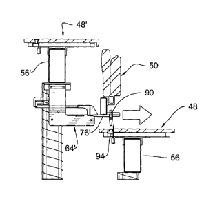
Each platform 48, for example second platform 48' as shown in figures 3-6,
comprises a seat stowing structure, generally identified with numeral 60'.
Seat stowing
structure 60' is more particularly attached to the lower side 48b' of second
platform 48'
wherein seat member 50 may be stowed on stowing structure 60' in a stowed
position when
it is not in its operative position.
Although first platform 48 in figures 3-6 is not illustrated as equipped with
a
seat stowing structure for clarity purposes, it is understood that most if not
all platforms,
including first platform 48, could be equipped with a seat stowing structure.
Seat stowing structure 60' comprises a pair of rail members 62', 64'. Each
rail member, for example rail member 62', comprises a pair of spaced-apart,
parallel L-
shaped rail plates 66', 68' fixedly attached to the underside of beam 56' that
carry three
rollers 70', 72', 74' (figure 5) therebetween. A flat rod-like carriage 76' is
carried by and
between rollers 70', 72', 74' so as to be movable along a horizontal
direction. A carriage
actuator 78' is capable of moving carriage 76' along said horizontal
direction. Carriage
actuator 78' can be a screw jack as shown in the drawings, or alternately any
other suitable
actuator such as a hydraulic cylinder or the like.
A seat member 50, stowed underneath second platform 48', is destined to be
selectively installed on first platform 48 as detailed hereinafter. Although
first platform 48 in
figures 3-6 is not illustrated as equipped with a stowed seat member for
clarity purposes, it is
understood that most if not all platforms, including first platform 48, could
be equipped with
a stowed seat member on its seat stowing structure.
CA 02740563 2011-04-14
WO 2010/057309 PCT/CA2009/001681
Seat member 50 comprises a seat support structure in the form of a beam 80
that carries a number of seats 82. Seat member 50 also has a pair of support
feet 84, 86
fixedly attached to the underside of beam 80 and extending perpendicularly
away from beam
80.
5
Seat member 50 may consequently rest on seat stowing structure 60' in its
stowed position. More particularly, the seat member's support feet 84 and 86
may rest on the
carriages 76' of rail members 62' and 64', respectively, as shown in figures 3
and 5.
Furthermore, upon activation of carriage actuators 78', carriages 76' may be
moved along
said horizontal direction thereby carrying seat member 50 in a horizontal
displacement along
1 o
said horizontal direction as further detailed hereinafter. Rail member 62',
carriage 76' and
carriage actuator 78' are herein considered to collectively form a horizontal
seat displacer.
According to one alternate embodiment of the invention (not shown), the seat
member could be pivoted from its stowed position either directly into its
operative position
or first in a position above the first platform, to then move the platform
relative to the seat
member until the seat member is in its operative position. This pivotal
displacement would
be accomplished by providing suitable pivotal seat displacement means such as
a pivotable
carriage that is pivotally carried by the second platform, instead of the
linearly displaceable
carriage 76' shown in the annexed drawings. It is understood that the
horizontal seat
displacer referred to in the present specification includes such alternate
seat displacement
means such as a pivotal displacer that includes a horizontal displacement
component, and
not just those seat displacers that include exclusively a horizontal
component.
Removable seats system 46 further comprises first and second
complementary male-female wedge members respectively provided on platforms 48,
48'
and on seat members 50. More particularly, seat members 50 comprise male wedge
members in the form of pin members 88, 90 that are fixedly attached to and
downwardly
depend from support feet 84, 86. Each pin member, for example pin member 88
shown in
figure 9, comprises a generally cylindrical outer wall that tapers towards its
lower extremity.
Platform 48 in turn comprises female wedge members in the form of sockets
92, 94 fitted in holes of corresponding shape made in platform 48 . Each
socket, for example
socket 92 shown in figures 7-9, comprises a sleeve or main body 96 fitted in
the platform
hole and an inner bore 98 in main body 96, with the inner bore 98 tapering
towards its lower
extremity.
CA 02740563 2011-04-14
WO 2010/057309 PCT/CA2009/001681
11
The size and configuration of pin member 88 and socket 92 are such that the
releasable engagement or insertion of pin member 88 within socket 92 along
their axes, as
suggested in figure 9, will result in a releasable wedging relationship
between the two as the
tapering wall of pin member 88 slides along and engages the complementary
tapering wall
of socket bore 98. To obtain an optimal wedging relationship, the taper angle
on pin member
88, 90 is preferably similar, if not identical, to the taper angle of bore 98.
It is understood that the relative position of the pin members and sockets
could be inverted, namely the pin members could be provided on the platforms
and the
sockets on the seat members, with only marginal design modifications
(including,
presumably, arranging the pin members so that they would not protrude from the
platform
upper side 48a). Considering that the pin members and sockets are thus
theoretically
interchangeable, each pin member with its corresponding socket are herein said
to form a
pair of complementary male-female wedge members.
It is further understood that sockets 92, 94 could be formed integrally in
platform 48. That is to say, sockets 92, 94 are shown in the drawings to have
a cylindrical
main body 96 fitted in a hole in platform 48; while alternately, the socket
bore could be
made directly in platform 48. One advantage of having a distinct socket body
however, is
that the hardness of the socket main body 96 is desirably more important than
that of
platform 48 itself to resist the load of pin member 88 therein (as seen
hereinafter, the
combined load of seat member 50 and attendees is transferred through pin
member 88 to
socket 92), without having to provide the entire platform flat wall 54 with a
material having
a similar hardness. In any event, the expression socket as used herein
generally refers to a
female member having a receiving end for receiving a complementary male member
such a
pin members 88, 90.
As shown in the drawings and in particular in figures 7-9, socket 92
comprises a cap 100 pivotally connected to main body 96 and movable between an
opened
position (figures 7 and 9) in which access to tapering bore 98 is allowed and
a closed
position (figure 8) in which bore 98 is covered. A cap actuator 102 is
provided to selectively
control the position of cap 100 and a biasing member in the form of a coil
spring 104 is also
provided to continuously force cap 100 towards its closed position.
In use, in the case where all seat members 50 in room 40 are in their stowed
position as shown in figures 3 and 10, all platforms 48 of room 40 may be
positioned at a
same vertical height to collectively form a uniformly flat floor surface where
attendees in
CA 02740563 2011-04-14
WO 2010/057309 PCT/CA2009/001681
12
room 40 may stand or where other furniture such as tables and chairs may be
installed. To
change the configuration of room 40 from its free floor configuration to its
theatre room
configuration wherein seat members 50 are provided in their operative position
for the
attendees, removable seats system 46 allows a transformation in room 40 during
which
platforms 48 and seat members 50 are moved as follows.
Figures 10-15 sequentially show how a seat member 50 may be moved from
its stowed and concealed position underneath second platform 48' to its
operative position
whereby seat member 50 will rest atop first platform 48.
Initially, seat member 50 is carried by rail members 62', 64' underneath
o second platform 48' in its stowed position as shown in figure 10. More
particularly, the seat
member support feet 84, 86 rest on the rail member carriages 76' (see also
figure 4). As
suggested in figure 10, each seat 82 may be folded upon itself to occupy less
space. The caps
100 of sockets 92, 94 are in their closed position to cover bores 98.
With seat member 50 in its stowed position, platform top surface 48a is free
and platform 48 participates in the so-called free floor configuration of room
40. All
platforms 48 in room 40 can be positioned adjacent one another to form a
continuous, free
and flat floor surface as mentioned above. As shown in figure 10, the gap or
play between
first and second adjacent platforms 48, 48' is small or inexistent: in other
words, adjacent
first and second platforms 48, 48' may abut one another along their
longitudinal edges or
may include platform stabilizing means (not shown) that bridge across first
and second
platforms 48, 48' to prevent relative movement thereof. This provides a stable
engagement
of platforms 48, 48' against each other, helping to prevent or reduce
perceptible movements
and vibrations.
To move seat member 50 from its stowed position to its operative position,
second platform 48' is first raised relative to first platform 48 as shown in
figure 11. This
vertical displacement is accomplished by means of platform actuator 52'
raising second
platform 48' to a selected vertical position in which seat member 50
vertically clears first
platform 48, or by lowering first platform 48, or both raising second platform
48' and
lowering first platform 48.
Socket caps 100 are opened to allow access into sockets 92, 94.
Then, as shown in figure 12, the carriage actuators 78' move carriages 76'
horizontally over first platform 48, concurrently carrying seat member 50 over
first platform
CA 02740563 2011-04-14
WO 2010/057309 PCT/CA2009/001681
13
48. More particularly, seat member 50 will be moved over first platform 48
until pin
members 88, 90 become vertically aligned with corresponding sockets 92, 94.
Figure 13 shows that platform actuator 52' then lowers second platform 48'
until seat member 50 comes to rest on second platform 48. The load of seat
member 50 is
consequently transferred from carriages 76' to second platform 48, still
through support feet
84, 86 albeit through the instrumentality of pin members 88, 90 engaging
sockets 92, 94.
More particularly, pin members 88, 90 of seat member 50 will be inserted and
wedged into
their corresponding sockets 92, 94 of first platform 48 due to the
complementary tapered
shapes of pin members 88, 90 and sockets 92, 94. These complementary tapered
shapes of
pin members 88, 90 and sockets 92, 94 allow a stable, releasable, wedged inter-
engagement
of pin members 88, 90 and sockets 92, 94 which in turn allows seat member 50
to stably rest
on platform 48. Seat member 50 does not contact first platform 48 at any other
point than
between pin members 88, 90 and sockets 92, 94 when it is in its operative
position.
Even very small relative movements between seat member 50 and first
platform 48 would be perceptible by a person sitting in seat member 50.
Consequently, the
complementary tapered shape of pins 88, 90 and sockets 92, 94 are very
advantageous in
preventing a loose engagement while still allowing pins 88, 90 from easily
engaging and
then releasing and disengaging sockets 92, 94 when seat member 50 is being
removed (as
detailed hereinafter). Furthermore, the complementary tapered shape of pin
members 88, 90
and sockets 92, 94 further allows for an auto-alignment of seat member 50
during
installation. Indeed, small positional deviations may exist between the axes
of pint members
88, 90 and that of the bores 98 of sockets 92, 94 when they are being aligned
before seat
member is lowered for the wedged engagement of pins 88, 90 into sockets 92,
94. The
complementary tapered shapes of pin members 88, 90 and sockets 92, 94 allows
to correct
small misalignments by the sloping peripheral wall of pin members 88, 90
sliding against
and into the sloping peripheral wall of sockets 92, 94.
The installation of seat member 50 according to the present invention is
further advantageous in that seat member 50 is not moved along the platform
top surface,
either in sliding or rolling engagement as in some prior art systems, avoiding
the platform
top surface 48a from being damaged. Not only that, but the seat member tapered
pin
members 88, 90 being lowered into sockets 92, 94 allows for very punctual
contact points
between the seat member and the platform. By providing pin members 88, 90 and
sockets
92, 94 with an inherent hardness which is much greater than that of the
platform 48 top
CA 02740563 2011-04-14
WO 2010/057309 PCT/CA2009/001681
14
surface, production costs are limited to a minimum while the hardness at these
contact points
will remain sufficiently high.
As a consequence, the actual visible top surface 48a of platform 48 is never
contacted, either dynamically or statically, by seat member 50, which prevents
it from being
damaged by seat member 50 aesthetically or structurally. This significantly
limits the wear
of platform top surface 48a.
As mentioned hereinabove, seat member 50 could alternately be moved from
its stowed position to its operative position through a displacement that is
not exclusively
linearly horizontal, such as a pivotal displacement (not shown) of seat member
50. This
1 o pivotal displacement could first position pin members 88, 90 spacedly
above sockets 92, 94
similarly to what carriages 76' accomplish; or they could even pivot seat
member 50 from
its stowed position directly into its operative position. Generally, any
displacement that
includes at least a horizontal component is considered to be included within
the scope of the
present invention's horizontal displacement. Even in such alternate
displacements of seat
member 50, seat member 50 remains positioned spacedly over platform 48 during
this
displacement to maintain a single contact point between seat member 50 and
platform 48 at
pin members 88, 90 and sockets 92, 94.
As shown in figure 14, once seat member 50 rests on first platform 48,
carriages 76', now relieved of the load of seat member 50, may be retrieved by
activating
carriage actuators 78' to move carriages 76' rearwardly underneath second
platform 48'.
Next, as shown in figure 15, platform actuator 52' is activated to lower
second
platform 48' at a desired height, for example coplanar to first platform 48.
An attendee may
now sit on seat member 50. The wedged relationship between tapered pins 88, 90
and the
complementary tapered sockets 92, 94 prevents any horizontal or pivotal
movement of seat
member 50 relative to first platform 48. Indeed, the load of seat member 50
and of any
attendees seated thereon contribute to stabilize seat member 50 by applying a
downward
force in the direction of the axes of pin members 88, 90 and sockets 92, 94,
thereby stably
maintaining the wedged engagement of pins 88, 90 into sockets 92, 94.
The above explanations with reference to figures 10-15 have shown how one
seat member 50 may be installed on one platform 48. This procedure may be
repeated to
install numerous seat members in room 40, for example one seat member on each
platform,
to form a number of aisles each comprising one or more coextensive platforms
one which
one or more seat members are installed. So in the example of figures 10-15, a
third platform
CA 02740563 2011-04-14
WO 2010/057309 PCT/CA2009/001681
(not shown) could be located rearwardly adjacent to second platform 48' and be
provided
with a second seat member in a stowed position underneath this third platform.
Following
the above-described steps to install a seat member, this second seat member
would be
moved from its stowed position to an operative position on second platform
48'. Likewise, a
5
third seat member (not shown) could be provided in a stowed position
underneath first
platform 48, to install this third seat member in an operative position on a
fourth platform
(not shown) that would be located frontwardly adjacent to first platform 48.
Thus, each
platform 48 in room 40 may have a stowed seat member 50 underneath it to
install the seat
member atop a frontwardly adjacent platform 48. The rows of platforms 48 will
simply be
o
sequentially vertically moved to allow each seat member 50 to be sequentially
installed on
its frontwardly adjacent platform 48. In the end, platforms 48 may be
positioned at a desired
elevation for the rows of seats to be either coplanar or sloping, for example
they may
gradually rise towards the back of room 40 if a gradually rising seat
configuration is desired
as is usual in theatre rooms and as suggested in figure 2.
15 To
remove a seat member 50 from its operative position on first platform 48,
the above-mentioned steps are accomplished in the opposite order: second
platform 48' is
raised; the carriages 76' are moved forwardly until they extend underneath the
seat member
support feet 84, 86; second platform 48' is raised again with carriages 76'
engaging seat
member support feat 84, 86 to allow seat member 50 to be vertically lifted
spacedly over
first platform 48 until pin members 88, 90 disengage and vertically clear
sockets 92, 94; and
carriages 76' are then moved rearwardly, carrying seat member 50 underneath
second
platform 48' to its stowed position. Second platform 48' may be moved to a
desired vertical
height, for example so as to be coplanar with first platform 48. Socket caps
100 are finally
closed to conceal the socket inner bores 98.
Figures 17-20 focus on the engagement of one carriage 76' with its
corresponding support foot 84 during the steps of moving seat member 50 from
its operative
to its stowed position. In figures 17 and 18, the forward movement of carriage
76'
underneath support foot 84 is sequentially suggested. Figures 19 and 20 in
turn sequentially
show the vertical displacement of carriage 76' as it is lifted concurrently
with second
platform 48' to engage foot member 84 and lift seat member 50.
It is noted again that vertical movement of second platform 48' is made
relatively to first platform 48 and that consequently this vertical movement
could be
accomplished by moving either one of second platform 48' or first platform 48
or both, as
CA 02740563 2015-12-17
16
long as the desired relative movement between the two is obtained. This is
true even though in
the present description it may occasionally be mentioned that one or the other
platform is
being moved independently from the other.
Figure 16 shows that a second seat member 50' can be concealed in a stored
position in a niche 110 formed in the fixed structure of room 40, for
installation on the second
platform 48' when the latter is in the rearmost row of platforms in room 40. A
seat stowing
structure 60" and a horizontal seat displacer are installed in niche 110,
similar to the seat
stowing structure 60' and the horizontal seat stowing structure provided on
the movable
platforms. Second platform 48' is vertically lowered for seat member 50' to be
installed
thereon.
It is noted that each seat member could be stowed under the rearwardly
adjacent (second) platform with respect to the platform on which it is to be
installed, under the
same (first) platform on which it is to be installed or under the frontwardly
adjacent platform
with respect to the platform on which it is to be installed. In the case where
it is stowed under
the frontwardly adjacent or rearwardly adjacent platform with respect to the
platform on
which it is to be installed, horizontal seat displacers such as the ones
disclosed hereinabove
may be used to horizontally move the seat away from and towards its stowed
position. If the
seat member is stowed under the same platform on which it is to be installed,
a different type
of seat displacer (not shown) should then be used, for example a seat
displacer that pivots the
seat member away from and towards its stowed position to bring it towards its
operative
position.
Figure 2 shows that platforms 48 may be provided with optional skirts 120
which
prevent access underneath platforms 48 when platforms 48 are vertically
offset.
Generally, removable seats system 46 of the present invention could be fully
automated or at least partly manual. For example, seat members SO could be
moved
horizontally along seat rails 36 either through the instrumentality of
automated carriage
actuators 78' as described hereinabove or alternately by manually pulling or
pushing on seat
member 50 to force carriages 76' to roll along rail members 62', 64'.
Likewise, the socket caps
100 could be opened and closed either automatically through electronic
controls or manually.
The manual approach is of course less expensive.
In one alternate embodiment of the invention (not shown), the seat member pin
members are cylindrical and engage complementary cylindrical socket bores. The
pin
members then preferably have very little play between them and their
corresponding sockets
to avoid or minimize movement of the seat relative to the platform.
CA 02740563 2011-04-14
WO 2010/057309 PCT/CA2009/001681
17
One way to avoid or minimize movement between the pin members and the
sockets is to include a locking mechanism for releasably locking the pins
within their socket
bores, in the operative position of the seat member. The wedging relationship
of the tapering
pin members in the complementary tapering bores is considered one embodiment
of a
locking mechanism in itself since it helps avoid accidental release of the pin
members from
the sockets. Indeed, once wedged into place, the pin members are likely to
require a
significant upward force to disengage their corresponding sockets, especially
if the seat
members are heavy. Other locking mechanisms (not shown) are also envisioned
such as a
transverse locking rod that would releasably engage both the socket and the
pin member
when the pin member engages the socket. Such other locking mechanisms could be
used if
the pin members and socket bores are of cylindrical shape or tapering.
In the alternate embodiment where the pin members are cylindrical, they might
be provided with a tapering tip to self-align with the bores when the seat
members are
lowered in the socket bores, even if the pin member peripheral wall portion
that engages the
socket bore is cylindrical.
Generally, it is understood that any suitable pair of complementary male-
female engagement members would be acceptable (although the embodiment
including
wedge members as engagement members as described hereinabove is particularly
advantageous). Indeed, one particular advantage of the present invention is to
provide male-
female inter-engagement between the seat member and the platform at designated
areas,
namely at a first male-female engagement member on the platform and at a
second male-
female engagement member on the seat member. This allows to control where the
load of
the seat member will be supported by the platform (namely, through the first
and second
male-female engagement member) to reinforce that particular area, for example
by
providing a socket and a pin member with suitable mechanical properties. It
also allows to
avoid compromising the structure of the platform to accommodate the seat
members and
damaging the platform by engaging the seat member on important regions
thereon. The
essentially punctual engagement and support of the seat member on the platform
at each pin
member-socket assembly is how this advantage is achieved. It is understood
however that
other elements than pin members as second engagement members could be used to
obtain
that advantage, including support plates or the like.