Note: Descriptions are shown in the official language in which they were submitted.
CA 02740778 2011-04-14
WO 2010/045418 PCT/US2009/060771
1
FLUID DISPENSING HAIR REMOVAL DEVICE
FIELD OF THE INVENTION
The present invention concerns hair removal devices, such as razors, which are
capable of
dispensing a fluid during use.
BACKGROUND OF THE INVENTION
Shaving devices capable of dispensing a fluid, such as a shaving preparation
or a lubricant are
known, but have a number of shortcomings.
A problem associated with some prior art fluid-dispensing razors is that the
fluid is loaded
directly into a reservoir disposed within the razor such that, on dispensing,
it may be replaced by
and come into contact with ambient air or, alternatively, it may directly
contact the dispensing
mechanism. These kinds of executions raise the prospect of contamination,
which, for a device
such as a razor, is a problem that must be avoided, especially if fluid
remains in the razor
between shaves, allowing microbial build-up. Such an execution is known from
WO 05/058560
A 1 .
FR-A-2 629 385 discloses a razor having an aerosol cartridge. Such devices are
complex and
expensive to produce. They also pollute the atmosphere with propellants and,
in addition, aerosol
canisters are generally not reusable, so must also be disposed of as well.
This patent application
also suggests replacing the pressurized cartridge with a liquid pump, but
provides no details of
either how to achieve that, or how to do so in a manner that maintains the
product to be dispensed
sterile.
WO 05/058560 Al discloses a fluid dispensing razor having a flexible bladder
filled with
shaving aid located in the handle. On actuating a button in the handle, a
ratchet mechanism
advances a piston which compresses the bladder to expel shaving aid through
holes located
around the shaving blades. This execution is mechanically complex to
manufacture and has the
disadvantage that the non-uniform application of pressure on the bladder may
result in the
accumulation of shaving aid in volumes where the pressure is lower, thereby
resulting in
incomplete emptying of the bladder during use.
CA 02740778 2011-04-14
WO 2010/045418 PCT/US2009/060771
WO 05/065897 discloses an arrangement comprising a bladder filled with shaving
aid. A pinch
roller driven by a drive mechanism serves to compress the bladder and expel
the shaving aid.
This arrangement is technically very complex.
Reference can also be made to GB 2 246 314 A, which teaches a razor in which a
tubular sack of
soap is disposed in the handle. Upon squeezing pressure plates in the handle,
spring plates are, in
turn, pressurized which squeeze the sack to force soap through holes in the
shaving head. Once
again, the non-uniform application of pressure to the external surface of the
sack, may cause soap
to accumulate in volumes of lower pressure such that it may not be not
possible completely to
empty the sack during use.
US 2006/0150386 A1 teaches a similar arrangement to that disclosed in the
preceding patent
application. According to this patent application, a razor is taught in which
a flexible bladder
comprising shaving agent is located within the handle. Dispensing takes place
by squeezing
flexible regions of the handle which act directly on the bladder to compress
it and expel shaving
agent. Once again, dispensing in this manner may result in incomplete emptying
of the bladder
and a concomitant waste of shaving agent.
It would be desirable to provide a fluid-dispensing hair removal device, which
is mechanically
simple to construct, which does not allow the fluid to come into contact with
ambient air or the
dispensing mechanism and which permits a more complete dispensing of fluid
during use than
traditional fluid-dispensing hair removal devices.
SUMMARY OF THE INVENTION
According to the invention, a hair removal device is provided, comprising a
handle and a
collapsible reservoir suitable for containing a fluid to be dispensed during
use of the hair removal
device, the hair removal device additionally comprising a deformably rigid
container enclosing
the collapsible reservoir, a fluid outlet adapted to allow fluid to exit both
the collapsible reservoir
and the deformably rigid container, a first one-way valve adapted to allow air
to enter but not exit
the deformably rigid container, and a pressure applicator, adapted to
pressurize air in the
deformably rigid container, thereby collapsing the collapsible reservoir and
causing fluid to be
expelled through fluid outlet.
CA 02740778 2011-04-14
WO 2010/045418 PCT/US2009/060771
3
BRIEF DESCRIPTION OF THE DRAWINGS
Figure 1 is a perspective view of a razor according to the present invention.
Figure 2A is a schematic view of a razor according to the present invention,
illustrating valves in
fluid dispensing mode.
Figure 2B is a schematic view of a razor according to the present invention,
illustrating valves in
air intake mode.
Figures 3A and 3B represent a detailed view of a particular embodiment of the
present invention,
illustrating how fluid may flow out of the hair removal device and air may
flow in.
DETAILED DESCRIPTION OF THE INVENTION
Hair removal devices according to the present invention comprise fluid
disposed within a
collapsible reservoir which reservoir is, itself, enclosed within a deformably
rigid container. The
deformably rigid container which encloses the collapsible reservoir must be
sufficiently rigid not
to collapse at the same time as the collapsible reservoir, although, as
discussed below, it can
comprise defoimable, non-rigid portion(s) as pressure applicator(s). Suitably
deformably rigid
materials of construction of the defomably rigid container include
polyethylene, polypropylene,
PET, PVC, and mixtures thereof. The deformably rigid container may be
comprised within the
handle of the fluid-dispensing hair removal device or, indeed, the handle of
the fluid-dispensing
hair removal device may itself define the deformably rigid container. If the
handle defines the
deformably rigid container, then the handle must be sufficiently deformably
rigid not only to
retain its shape as the collapsible reservoir collapses, but also to function
as a handle.
The collapsible reservoir may be manufactured separately from and then
introduced into the
deformably rigid container or the two may be manufactured together in a single
process.
In a preferred manufacturing process, the two are manufactured together in a
single process, such
that, following manufacture and prior to use, the collapsible reservoir is
removably laminated to
the deformably rigid container. An exemplary process includes extrusion blow
molding of a
multi-layer parison comprising an outer layer, which will become the
deformably rigid container,
an inner layer, which will become the collapsible reservoir and an
intermediate layer, between
the inner layer and the outer layer, which serves to prevent the inner and
outer layers from
peimanently adhering to one another. The intermediate layer may extend over
the entire
CA 02740778 2011-04-14
WO 2010/045418 PCT/US2009/060771
4
interfacial surface between the inner and outer layers, or may be left out at
some important
locations at the interface, such as at a fluid outlet, in order to effect
bonding between the inner
and outer layers at that or those locations and thereby prevent delamination
in those locations.
During the manufacturing process, the multi-layer parison is extruded and then
blown. In
subsequent use, air forced between the inner and outer layers acts to
"delaminate" or peel away
the inner layer forming the collapsible reservoir. The collapsible reservoir
thereby becomes
separated from the outer layer forming the defomably rigid container, while
the outer layer
enclosing the collapsible reservoir essentially retains its shape.
In an alternative, preferred manufacturing process, injection-moulded inner
and outer pre-forms
are assembled together and then subsequently blow-moulded to form the
collapsible reservoir
and the deformably rigid container.
Typical materials of construction of the collapsible reservoir include nylon,
PET, PVC, LDPE
polypropylene, and mixtures thereof. Evidently, if the collapsible reservoir
and the deformably
rigid container enclosing it are made of similar or identical materials, then
the necessary
differences in rigidity will be achieved in ways known to the skilled person,
such as via
differences in wall thicknesses. Reference may be made to the following
documents which
discuss technologies for making so-called "delaminating" or "multi-layer"
containers: US
5,316,135; US 5,447,687; US 5,501,625; US 6,244,852; US 6,109,468; US
5,435,452; US
5,513,761; US 5,567,377; US 5,711,454; US 5,921,438; US 6,691,494; US
6,266,943; US
6,691,494; US 6,266,943; US 6,670,007.
The collapsible reservoir must be contained within the deformably rigid
container in such a
fashion that any air introduced into the deformably rigid container will serve
to pressurize it and
collapse the collapsible reservoir, rather than flowing out again. It is
desired that air introduced
into the defollnably rigid container acts to pressurize the contents of the
container, as such, in one
embodiment the container does not contain any air outlets. As a result in one
embodiment, the air
inlet comprises a first one-way valve that allows air in but not out. Suitable
one-way valves
include umbrella or flapper valves and are known to the person skilled in the
art.
The fluid comprised within the collapsible reservoir must be allowed to exit
the collapsible
reservoir and the deformably rigid container for use during the hair removal
process. To facilitate
CA 02740778 2011-04-14
WO 2010/045418 PCT/US2009/060771
this, an opening is provided in the collapsible reservoir and a further
opening is provided within
the deformably rigid container and these openings are aligned with one another
and connected
together during the manufacturing process to provide a fluid outlet.
The collapsible reservoir must be connected to the deformably rigid container
in such a way at
the fluid outlet that air cannot escape from the container. This seal may be
effected in a number
of ways known by the skilled person. One such way is described above and
involves the
collapsible reservoir and the deformably rigid container being bonded together
during the
manufacturing process by virtue of their comprising materials which naturally
bond and by virtue
of omitting any intermediate layer in the vicinity of the fluid outlet to
prevent such bonding.
More typically, the collapsible reservoir and the deformably rigid container
are arranged such as
to be mechanically sealed together at the fluid outlet. For example, the
relative sizes of the
deformably rigid container and the collapsible reservoir at the fluid outlet
may be such that they
are forced together. If the collapsible reservoir and the deformably rigid
container are
manufactured together in a single manufacturing process, then an air-tight
seal, such as a
mechanical seal, may automatically result from that manufacturing process.
Advantageously, the fluid outlet is provided with a second one-way valve to
allow fluid to exit
but not enter the collapsible reservoir. This has the advantage of reducing
the possibility of
contamination of the fluid by contaminated air or by contaminated fluid being
drawn back into
the collapsible reservoir. Suitable one-way valves include duck-bill valves,
flapper valves, slit
valves and umbrella valves.
In order to pressurize the air in the deformably rigid container and cause the
collapsible reservoir
to collapse, the hair removal device must comprise a pressure applicator. In a
simple form, when
the collapsible reservoir is comprised within the handle, such a pressure
applicator may simply
comprise deformable portions of the handle, Such deformable portions may
suitably be made of
plastic or elastomeric material having memory, such that, following
deformation from its rest
position, it will tend to return to that rest position after removal of the
depression force. In use, on
depressing such a deformable portion, the air within the deformably rigid
container is
compressed, serving to collapse the collapsible reservoir and force fluid out
of the reservoir for
use during the hair removal process. As soon as the user ceases to depress the
deformable
portion, it returns to its rest position giving rise to an under-pressure
within the deformably rigid
CA 02740778 2013-05-15
6
container, which is compensated by air flowing into the container through the
first one-way
valve. Hair removal devices according to the invention may comprise one or
more pressure
applicators. In the event that the hair removal device comprises a plurality
of pressure
applicators, then the pressure applicators may have different capacities for
applying pressure. For
example, one pressure applicator may only apply a small pressure, thereby
effecting the
dispensing of a small amount of fluid, whereas another applicator may apply a
larger pressure
and effect the dispensing of a larger amount of fluid. The different
applicators may also comprise
information for the consumer to inform them of the different dispensing
capacities.
Ideally, the pressure applicator facilitates the displacement of an accurately
repeatable amount of
air that ideally corresponds to an accurately repeatable dispensed dosage of
fluid from the hair
removal device. Such a dosage may be at any desirable level, but is
advantageously from 0.001
to 4m1. A suitable device for displacing the same amount of air each time is a
so-called "mono-
stable button". As used herein, a mono-stable button is a button which, when
depressed from its
rest position, displaces a fixed volume of air, but then returns to its rest
position immediately
thereafter. In displacing a fixed amount of air, it causes essentially the
same amount of fluid to be
displaced from the hair removal device. Mono-stable buttons are frequently
used on telephone
key pads and for pumping fluid and priming liquid systems, such as in petrol
engines. Suitable
mono-stable buttons are known to those skilled in the art.
In one embodiment the pressure applicator comprises a dosing mechanism, to
ensure that the
same amount of air is displaced and a dose of fluid is dispensed every time
pressure is
applied.
In one embodiment the pressure applicator comprises one or more mono-stable
buttons,
whereby depressing a mono-stable button acts to pressurize the air by a
defined amount to
ensure that a dose of fluid is dispensed every time that the mono-stable
button is depressed
and releasing the mono-stable button causes it to return to its rest position
and draw air
through the first one-way valve into the deformably rigid container.
Preferably, the pressure applicator(s) will give a signal, such as a tactile
signal, for example a
click, to the user, that they have been actuated and, therefore, that
dispensing shall occur.
CA 02740778 2013-05-15
6a
In a further advantageous embodiment, the hair removal device may comprise a
plurality of
pressure applicators disposed at different locations on the handle, to allow
the user to grip the
handle in a plurality of different ways and yet still facilitate fluid
dispensing. For example, a user
may grip the handle in an entirely different way if he or she is holding the
device vertically or
horizontally, or making a long shaving stroke along a leg, or a short one on
an under-arm or the
face. In order to facilitate simple fluid dispensing in both orientations, the
hair removal device
may comprise a plurality of pressure applicators at situated different
locations, such as on
different parts of the handle, so that at least one is always within
comfortable range of a user's
finger.
CA 02740778 2011-04-14
WO 2010/045418 PCT/US2009/060771
7
Once fluid leaves the fluid outlet it enters the head of the hair removal
device to be distributed
onto the skin of the user. This may take place through one or more holes or
slits in the skin-
facing surface of the head.
In one embodiment, the head of the hair removal device comprises an applicator
for dispensing
the fluid. In one embodiment, the applicator is flat and wide for dispensing a
thin but wide
ribbon of the fluid. In one embodiment, the applicator forms a dispensing
orifice comprising a
smaller orifice dimension having a length of from about 0.5 mm to about 10 mm,
alternatively
from about 1 mm to about 3 mm, and a larger orifice dimension having a length
of from about 20
mm to about 80 mm, alternatively from about 30 mm to about 70 mm,
alternatively from about
40 mm to about 50 mm. Preferably, the smaller orifice dimension is a vertical
dimension and the
larger orifice dimension is a horizontal dimension. The smaller and larger
orifice dimensions are
measured as the vertical and horizontal distances, respectively between
opposing edges of the
applicator which foriris the orifice. This type of applicator is particularly
suitable when the
device contains a depilatory, a lubricating fluid, a moisturizer, or any other
suitable hair removal
composition. In one embodiment, the applicator has a spreading member which is
separate from
the dispensing orifice. When a spreading member is used, the device can
dispense the fluid via
one or more holes or slits which can be positioned proximally towards the
handle (where the
spreading member is positioned distally away from the deformably rigid
container) such that
when the user is pulling the device in a direction towards the handle, fluid
can be dispersed and
the spreading member can be used to spread the fluid onto the skin surface. In
one embodiment,
the spreading member has a length of from about 20 mm to about 80 mm,
alternatively from
about 30 mm to about 70 mm, alternatively from about 40 mm to about 50 mm.
In one embodiment, the applicator has a skin contacting edge which is flat,
concave or convex.
Those of skill in the art will understand that different shapes for the skin
contacting edge can be
preferred based on the desired part of the body upon which the device is
intended for use. For
example, a hair removal device intended for use on the face may have an
applicator having a
straight edge. A hair removal device intended for use on legs may have an
applicator having a
concave edge. Non-limiting examples of suitable head configurations are
disclosed in U.S.
Design Patent Nos. D399,601 to Desnos, D203,892 to Muscatiello, and 651,420 to
Haglock; U.S.
Patent Nos. 3,088,470 to Hall, 3,858,985 to Fiveash, 2004 0168743A1 to
Garwood; WO Publ.
No. 97/18043A1 to Weiss; and GB 1 390 153 to Laboratorio Guidotti & C. S.p.A.
CA 02740778 2011-04-14
WO 2010/045418 PCT/US2009/060771
8
Those of skill in the art will understand that the applicator can also serve
as a dispensing member
for a second fluid. In one embodiment, the applicator would include a slit
type orifice which
could remain in a closed orientation until pressure is applied, opening the
slit type orifice and
allowing fluid to dispense.
The handle of the hair removal device may be permanently or removably fixed to
the hair
removal device. Advantageously, the handle is detachable from the hair removal
device. If the
handle comprises the deformably rigid container enclosing the collapsible
reservoir, then such an
arrangement facilitates replacement of the collapsible reservoir. In such a
case, if the reservoir is
empty, then the handle, comprising the deformably rigid container and
collapsible reservoir are
simply removed and replaced by a new handle comprising a deformably rigid
container enclosing
a new collapsible reservoir which is full of fluid. The empty handle can then
be recycled.
The fluid-dispensing hair removal device according to the invention may be a
shaving device,
such as a razor, but is not limited to such devices and may instead be a
device which employs
other means, such as light, especially laser light, or even depilatories (as
disclosed in US Patents
4618344. 5645825A, 6743419, and US Patent Publication US2004/0228820A1), to
remove hair.
In one embodiment, the hair removal device comprises at least one of a razor,
a scraping edge or
scraper, a light, and a depilatory, optionally more than one. Like the
spreading edge, the scraper
or scaping edge can be straight, concave or convex shaped.
For the event that the hair removal device is a razor, then the razor
cartridge comprising the
blades may be permanently or removably fixed to hair removal device.
Advantageously, the
cartridge is detachable from the hair removal device, such that it may be
replaced, as needed.
The fluid comprised within the reservoir of the hair removal device is
advantageously a cosmetic
fluid, more preferably a shaving preparation. Examples of such fluids include,
but are not limited
to; oil-in-water emulsions, water-in-oil emulsions, single phase aqueous
polymer solutions, high
level surfactant based solutions. Within such fluids, additional ingredients
may be incorporated,
examples of which include: high molecular weight polymers, cationically
charged polymers,
lipid based materials, silicone based compounds, surfactants, vitamins and
vitamin derivatives,
skin conditioning agents, hair removal waxes, other hair removal compositions,
and depilatories.
CA 02740778 2011-04-14
WO 2010/045418 PCT/US2009/060771
9
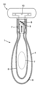
Reference is made to the figures, which disclose a non-limiting embodiment of
the invention.
Figure 1 illustrates a hair removal device (1) is disclosed in the form of a
razor, having a shaving
cartridge (10) comprising blades (not shown). The razor comprises a handle (2)
which acts as the
deformably rigid container (4) enclosing a collapsible reservoir, which, in
turn, contains fluid,
such as shaving aid, to be dispensed. Pressure applicators (7) may also be
seen, which are
configured as flexible portions of the handle (2). These pressure applicators
(7) may be depressed
by a user to pressurize the air space in the handle and thereby also the
collapsible reservoir (3),
thereby forcing fluid out of the collapsible reservoir (3).
Figures 2A and 2B are schematic drawings, illustrating some important
functional aspects of the
hair removal device (1) of figure 1.
Figure 2A illustrates the deformably rigid container (4), which may also be
the handle, which
encloses the collapsible reservoir (3). Pressure applicators (7) may also be
seen. These are
configured as flexible portions of the handle which have memory. In use they
may be depressed
on application of force by a user. Following removal of the applied force,
they return to their rest
state. Importantly, first one-way valve (6) is also shown, which functions to
allow air to enter the
deformably rigid container (4) but not exit. In Figure 2A, this valve is shut,
because the device is
in fluid-dispensing mode. As a result, fluid contained within the collapsible
reservoir is being
expelled (as indicated by the arrow) through fluid outlet (5) via second one-
way valve (8), which
is open. This has been effected by depressing, one or more of the pressure
applicators (7) to
compress the air in deformably rigid container (4) and thereby also compress
the collapsible
reservoir (3). This, in turn, causes fluid contained within the collapsible
reservoir to be expelled
via fluid outlet (5).
The features shown in Figure 2B are identical to those shown in Figure 2A,
except that this figure
illustrates the valves in air-intake mode: following release of the force
applied by the user, the
pressure applicator (7) returns to its rest state, thereby generating an under-
pressure in the
deformably rigid container (4), which, in turn, serves to draw air in via
first one-way valve (6), as
shown by the arrow, to allow the pressure to equilibrate within the deformably
rigid container
(4). As a result, first one-way valve (6) is shown open in this figure,
whereas the absence of
pressure on second one-way valve (8) has caused it to close, as shown.
CA 02740778 2013-05-15
Figures 3A and 3B illustrate a working embodiment of a valve system shown
schematically in
Figure. 2, Once again, The collapsible reservoir (3) and the defonnably rigid
container (4) are
shown. With reference to Figure 3A, in response to a pressure increase in the
defomiably rigid
container (4), fluid flows in the direction shown by the arrows through the
fluid outlet (5), which
is equipped with second one-way valve (8) to prevent fluid re-entry. Air may
not flow into the
deformably rigid container (4), because first one-way valve (6) is forced shut
by the increased
pressure. With reference to figure 3B, in response to a pressure decrease in
the deformably rigid
container (4), second one-way valve (8) is forced shut, but first one-way
valve (6) opens to allow
air to flow in the direction of the arrows, There is an air gap (not shown)
through threaded
portion (11) to allow air to flow through an opening (12) and thereby into the
space between the
collapsible reservoir (3) and the deformably rigid container (4).
The dimensions and values disclosed herein are not to be understood as being
strictly limited to
the exact numerical values recited, Instead, unless otherwise specified, each
such dimension is
intended to mean both the recited value and a functionally equivalent range
surrounding that
value. For example, a dimension disclosed as "40 mm" is intended to mean
"about 40 mm."
The citation of any document is not an admission that it is prior art with
respect to any
invention disclosed or claimed herein or that it alone, or in any combination
with any other
reference or references, teaches, suggests or discloses any such invention.
Futther, to the extent
that any meaning or definition of a term in this document conflicts with any
meaning or
definition of the same term in a document cited herein, the meaning or
definition
assigned to that term in this document shall govern.
While particular embodiments of the present invention have been illustrated
and described,
the scope of the claims should not be limited by the preferred embodiments set
forth in the
drawings, but should be given the broadest interpretation consistent with the
description as a
whole.