Note: Descriptions are shown in the official language in which they were submitted.
CA 02741158 2016-04-19
WO 2010/046356 PCT/EP2009/063723
Multifocal Intraocular Lens
FIELD OF THE INVENTION
The present application generally relates to lenses and related methods that
can replace or
supplement the lens of a human eye, more particularly to multifocal lenses and
related methods
that provide two or more optical powers within a single optic or optical zone.
BACKGROUND OF THE INVENTION
Intraocular lenses (IOLs) and other ophthalmic lenses have been configured to
provide
multiple foci, for example, to provide both distant vision and near vision to
a subject, thus at
least approximating the accommodative ability of the natural lens in a younger
subject.
Examples of such lenses are disclosed in United States Patent Number (USPN )
6,536,899 to
Fiala; 1JSPNs 5,225,858; 6,557,998; 6,814,439; 7,073,906 to Portney; USPN
7,188,949 to
Bandhauer; and USPN 7,093,938 to Morris.
Such multifocal or bifocal ophthalmic lenses may generally be classified as
multifocal
diffractive lenses or multifocal refractive lenses. Various advantages and
disadvantages have
been associated with each class or type of multifocal lens. One approach for
incorporating the
benefits of each class of multifocal lens is to use a multifocal diffractive
lens in one eye and a
multifocal refractive lens in the other eye.
A common problem with multifocal 10Ls is that of halo pattems or images that
can occur
when an out-of-focus image associated with one of the foci is superimposed
with an in-focus
image associated with another focus of the lens. For example, a distant
automobile headlight,
when seen through a typical diffractive bifocal lens, appears as an in-focus
spot on the retina of
the eye and an out-of-focus blur spot surrounding the in-focus spot and having
a distinct outer
border. This distinct outer border has been found to be annoying to users and
various efforts
have been made to soften this border so that the halo spot is less noticeable.
Multifocal ophthalmic lenses are needed that incorporate the advantages of
both
multifocal diffractive and multifocal refractive intraocular lenses within a
single optic in
synergistic ways that enhance the optical performance over traditional
multifocal lenses and/or
CA 02741158 2011-04-19
WO 2010/046356
PCT/EP2009/063723
reduce the effects of halo images.
BRIEF DESCRIPTION OF THE DRAWINGS
FIG. 1 is a side view of an eye containing a natural crystalline lens.
FIG. 2 is a side view of the eye in FIG. 1 with an intraocular lens according
to an
embodiment of the present invention.
FIG. 3 is a side view of a cross-section of the intraocular lens shown in FIG.
2 showing
diffractive and refractive profiles and their associated base shapes or
curvatures.
FIG. 4 is a side view of a cross-section of the intraocular lens shown in FIG.
2.
FIG. 5 is a plan view of the posterior surface of the intraocular lens shown
in FIG. 4.
FIG. 6 is a plot of the refractive add power of a multifocal refractive
profile for the
intraocular lens shown in FIG. 5.
FIG. 7 is side =view of a cross-section of a multifocal lens according another
embodiment
of the present invention.
FIG. 8 is a side view of a cross-section of a multifocal lens according to yet
another
embodiment of the present invention.
FIG. 9 is a plot of refractive and diffractive characteristics of the
multifocal lens shown in
FIG. 8.
DETAILED DESCRIPTION OF THE DRAWINGS
The present invention is directed to multifocal lenses, lens systems, and
associated
methods of making or use thereof. Embodiments discussed herein are generally
directed to
= intraocular lenses; however, other types of lenses are anticipated,
especially other types of
ophthalmic lenses, such as contact lenses, corneal implants, spectacles, and
the like. In some
embodiments, a corneal surgical procedure, such as a LASIK or PRK procedure,
are conducted to
provide optical aspects of the lenses discussed below.
In certain embodiments, an optic provides multifocal and/or extended focus
performance
through the use of a multifocal refractive element or profile in combination
with a diffractive
element or profile. The diffractive element may be a bifocal or multifocal
diffractive element,
wherein light within the visible range of the electromagnetic spectrum is
directed two or more
2
CA 02741158 2011-04-19
WO 2010/046356 PCT/EP2009/063723
diffraction orders and/or foci. Alternatively, the diffractive element may be
a monofocal
diffractive element, wherein light within the visible range of the
electromagnetic spectrum is
directed completely or substantially completely to a single diffraction order
and/or focus. In
certain embodiments, a multifocal diffractive profile is provided on all or
part of one surface of
an optic, while a multifocal refractive profile is provided on all or part of
an opposite surface of
the optic. Alternatively, the multifocal diffractive profile and the
multifocal refractive profile
may be provided on a common surface. In some embodiments, multifocal
diffractive and the
multifocal refractive profiles are disposed on different, distinct, or non-
overlapping portions or
apertures of the optic. Alternatively, portions of the multifocal diffractive
profiles and the
multi focal refractive profiles may overlap within a common aperture or zone
of the optic. In any
of these embodiments, combinations of a multifocal refractive element with a
diffractive element
may be configured to offer a design or designer more flexibility in providing
a predetermined
balance between near and distant vision as a function of pupil size or
lighting conditions. Such
combinations also be configured to soften halo images by providing more
flexibility and design
parameters for adjusting the distribution of light within a halo cross-
section.
As used herein, the terms "about" or "approximately", when used in reference
to a
Diopter value of an optical power, mean within plus or minus 0.5 Diopter of
the referenced
optical power(s). As used herein, the terms "about" or "approximately", when
used in reference
to a percentage (%), mean within plus or minus one percent ( 1%). As used
herein, the terms
"about" or "approximately", when used in reference to a linear dimension
(e.g., length, width,
thickness, distance, etc.) mean within plus or minus one percent (1%) of the
value of the
referenced linear dimension.
As used herein, the terms "light" or "visible light" mean electromagnetic
radiation within
the visible waveband, for example, electromagnetic radiation with a wavelength
in a vacuum that
is between 390 nanometers and 780 nanorneters. As used herein, the term
"optical power" of a
lens or optic means the ability of the lens or optic to converge or diverge
light to provide a focus
(real or virtual) when disposed within a media having a refractive index of
1.336 (generally
considered to be the refractive index of the aqueous and vitreous humors of
the human eye), and
is specified in reciprocal meters or Diopters (D). See 1S0 11979-2. As used
herein the terms
"focus" or "focal length" of a lens or optic is the reciprocal of the optical
power. As used herein
3
CA 02741158 2011-04-19
WO 2010/046356 PCT/EP2009/063723
the term "power" of a lens or optic means optical power. As used herein, the
term "refractive
power" or "refractive optical power" means the power of a lens or optic, or
portion thereof,
attributable to refraction of incident fight. As used herein, the term
"diffractive power" or
"diffractive optical power" means the power of a lens or optic, or portion
thereof, attributable to
the diffraction or constructive interference of incident light into one or
more diffraction orders.
Except where noted otherwise, optical power (either absolute or add power) of
an intraocular lens
or associated optic is from a reference plane associated with the lens or
optic (e.g., a principal
plane of an optic). In this respect, an intraocular lens with a base or add
power of 4.0 Diopters is
approximately equal to an optical power of about 3.2 Diopters in a spectacle
lens.
As used herein, the term "clear aperture" means the opening of a lens or optic
that
restricts the extent of a bundle of light rays from a distant source that can
be imaged or focused
by the lens or optic. The clear aperture is typically circular and specified
by its diameter,
although other shapes are acceptable, for example, oval, square, or
rectangular. Thus, the clear
aperture represents the full extent of the lens or optic usable for forming a
conjugate image of an
object or for focusing light from a distant point source to a single focus, or
to a plurality of
predetermined foci in the case of a multifocal optic or lens. It will be
appreciated that the term
clear aperture does not limit the transmittance of the lens or optic to be at
or near 100%, but also
includes lenses or optics having a lower transmittance at particular
wavelengths or bands of
wavelengths at or near the visible range of the electromagnetic radiation
spectrum. ln some
embodiments, the clear aperture has the same or substantially the same
diameter as the optic.
Alternatively, the diameter of the clear aperture may be smaller than the
diameter of the optic, for
example, due to the presence of a glare or posterior capsular pacification
(PCO) reducing
structure disposed about a peripheral region of the optic.
As used herein, the term "diffraction efficiency" is defined as the light
energy, power, or
intensity at a particular wavelength that is diffracted into a particular
diffraction order of a
diffractive optic, element, or portion divided by the total light energy,
power, or intensity at the
particular wavelength that is useful in providing vision or that is contained
in all diffractive
orders configured to provide near, intermediate, or distant vision when placed
in a model eye
(real or mathematical) or in an eye of a patient or mammalian subject. By this
definition, a
monofocal diffractive optic, element, or portion has a diffraction efficiency
of 100%, while a
4
CA 02741158 2011-04-19
WO 2010/046356 PCT/EP2009/063723
multifocal diffractive optic, element, or portion with blazed profile
configured to produce zeroth
and first diffraction orders in the visible range has a diffraction efficiency
of 50% for each of two
foci in the visible.
A multifocal optic, lens, refractive profile or structure, or diffractive
profile or structure is
generally characterized by base power and at least one add power. As used
herein the term "base
power", when used in reference to an optic or lens, means a power (in
Diopters) of an optic or
lens required to provide distant vision at the retina of a subject eye. As
used herein the term
"base power", when specifically applied to a refractive profile or diffractive
profile, means a
reference power (e.g., zero or about zero Diopters, or the power of a lower
diffraction order of
the diffractive profile used to provide more distant vision) from which one or
more add powers
of the profile or structure may be measured or compared. As used herein, the
term "add power"
means a difference in optical power (in Diopters) between a base power and a
second power of
an optic, lens, profile, or structure. When the add power is positive, the sum
of the add power
and the base power corresponds to a total optical power suitable for imaging
an object at some
finite distance from an eye onto the retina. A typical maximum add power for
an optic or lens is
the range of about 3 Diopter to about 4 Diopters in the plane of the lens;
however, this number
may be as high as 6 Diopters or more. An add power in Diopters may be directly
related to an
object distance from an eye by the relationship d = 1 / D, where d is the
object distance in meters
and D is the add power in Diopters. For example, an add power of 1 Diopter is
suitable for
focusing an object onto the retina that is located at a distance of I meter
from an ernmetropic eye
in a disaccommodative state (e.g., with a relaxed ciliary muscle), while add
powers of 0.5
Diopter, 2 Diopters, 3 Diopters, and 4 Diopters are suitable for focusing an
object onto the retina
that is located at a distance of 2 meters, 50 cm, 33 cm, and 25 cm,
respectively, from an
emmetropic eye in a disaccommodative state.
As used herein, the term "near vision" means vision produced by an eye that
allows a
subject to focus on objects that are at a distance of 40 cm or closer to a
subject (i.e., at least 2.5
Diopters of add power), typically within a range of 25 cm to 33 cm from the
subject (i.e., 3
Diopters to 4 Diopters of add power), which corresponds to a distance at which
a subject would
generally place printed material for the purpose of reading. As used herein,
the term
"intermediate vision" means vision produced by an eye that allows a subject to
focus on objects
CA 02741158 2011-04-19
WO 2010/046356 PCT/EP2009/063723
that are located between 40 cm and 2 meters from the subject (i.e., having an
add power between
2.5 Diopters and 0.5 Diopters). As used herein, the term "distant vision"
means vision produced
by an eye that allows a subject to focus on objects that are at a distance
that is greater than 2
meters, typically at a distance of about 5 meters from the subject, or at a
distance of about 6
meters from the subject, or greater.
Referring to HG. 1, a cross-sectional view of a phakie eye containing the
natural
crystalline lens is shown in which an eye 10 includes a retina 12 that
receives light in the form of
an image produced when light from an object is focused by the combination of
the optical powers
of a cornea 14 and a natural crystalline lens 16. The cornea 14 and lens 16
are generally disposed
about an optical axis OA. As a general convention, an anterior side is
considered to be a side
closer to the cornea 14, while a posterior side is considered to be a side
closer to the retina 12.
The natural lens 16 is enclosed within a capsular bag 20, which is a thin
membrane
attached to a ciliary muscle 22 via zonules 24. An iris 26, disposed between
the cornea 14 and
the natural lens 16, provides a variable pupil that dilates under lower
lighting conditions
(mesopic or scotopic vision) and constricts under brighter lighting conditions
(photopic vision).
The ciliary muscle 24, via the zonules 24, controls the shape and position of
the natural lens 16,
allowing the eye 10 to focus on both distant and near objects. It is generally
understood that
distant vision is provided when the ciliary muscle 22 is relaxed, wherein the
zonules 24 pull the
natural lens 16 so that the capsular bag 20 and lens 16 are generally flatter
and provide a longer
focal length (lower optical power). It is generally understood that near
vision is provided when
the ciliary muscle contracts, thereby relaxing the zonules 24 and allowing the
capsular bag 20
and lens 16 to return to a more rounded state that produces a shorter focal
length (higher optical
power).
Referring to FIG. 2, a cross-sectional view of a pseudophakic eye is shown in
which the
natural crystalline lens 16 has been replaced by an intraocular lens 100
according to an
embodiment of the present invention. The imraocular lens 100 comprises an
optic 102 and
haptics 103, the haptics 103 being configured to at least generally center the
optic 102 within the
capsular bag 20, provide transfer of ocular forces to the optic 102, and the
like. Numerous
configurations of haptics 103 relative to optic 102 are well know within the
art, and embodiments
of the present invention may generally be applied to any of these. The optic
102 is configured to
6
CA 02741158 2011-04-19
WO 2010/046356
PCT/EP2009/063723
provide two or more foci, for example, to provide a subject with both distant
vision and near
vision, to provide a subject with both distant vision and intermediate vision,
or provide a subject
with distant vision, intermediate vision, and near vision, as is explained in
greater detail below.
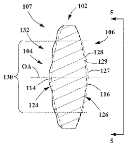
Referring to FIGS. 3-5, only the optic 102 of the intraoeular lens 100 is
shown (i.e.,
haptics 103 are not shown). The optic 102 comprises an anterior surface 104
and an opposing
posterior surface 106. The optic 102 also has a clear aperture 107 disposed
about the optical axis
OA. The anterior surface 104 has an anterior base shape, figure, or curvature
114, while the
posterior surface 106 has a posterior base shape, figure, or curvature 116.
The base shapes 114,
116 provide a base optic 102 power that generally provides distant vision. The
base optic 102
power is generally between -20 Diopters and +60 Diopters, typically between
about +10 Diopters
and about +40 Diopters.
The optic 102 also includes a multifocal refractive profile or element 124
imposed on,
added to, or combined with the anterior base shape 114. In the illustrated
embodiment, the
refractive profile 124 is symmetrically disposed about the optical axis OA
over a radial extent
from the optical axis= OA that includes =the entire clear aperture 107 of the
optic 102.
Alternatively, the refractive profile 124 may be asymmetric disposed, may have
a radial extent
that is less than the entire clear aperture 107, and/or may have an inner
radius that starts as a
predetermined distance from the optical axis OA. The multifocal refractive
profile 124 in FIGS.
3 and 4 is an undulating surface that has been exaggerated along the optical
axis OA for
illustrative purposes. In general, the local optical power of the multifocai
refractive profile 124 is
varied with radius from the optical axis OA by varying the local radius of
curvature. The
multifocal refractive profile 124 includes one or more portions having a base
refractive power
that is zero or about zero Diopter, or that has an average optical power that
is zero or about zero
Diopter. The multifocal refractive profile 124 also includes one or more
portions having an add
power or average add power that is added to the base refractive power,
typically having a value
of between about 1 Diopter and 4 Diopters. In some embodiments, the multifocal
refractive
profile 124 may include portions that have an add power or average add power
that is negative,
for example, about -1 Diopters.
With additional reference to FIG. 6, the refractive profile 124 of the
illustrated
embodiment includes a portion 125a that has an average optical power of about
zero Diopters.
7
CA 02741158 2011-04-19
WO 2010/046356
PCT/EP2009/063723
The multifocal refractive profile 124 also includes an portion 125b having an
add power that
varies continually with radius and having a maximum refractive add power of
about 2 Diopters.
The multifocal refractive profile 124 also includes a portion 125c having a
constant power of
zero Diopters, for example, to provide additional distant vision for larger
pupil sizes or under
scotopic lighting conditions.
The optic 102 further includes a multifocal diffractive profile or eleinent
126 that is
imposed on, added to, or combined with the posterior base shape 116. The
multifocal diffractive
profile 126 generally comprises a central echelette 127 surrounded by a
plurality of annular
echelettes 128, whereby the height of steps 129 between adjacent echelettes
127, 128
(exaggerated in FIGS. 3, 4 for illustrative purposes) and the shape of the
echelettes 127, 128 are
selected to provide constructive interference between echelettes for incident
light on the optic
102 to produce two or more foci. The multifocal diffractive profile 126 may
have, for visible
light, a primary diffraction order, a secondary diffraction order, and a
diffractive add power
corresponding to a difference in optical power between the secondary
diffraction order and the
primary diffraction order. In some embodiments, the primary diffraction order
is a zeroth
diffraction order having an optical power of or about zero Diopters and the
secondary diffraction
order is a first diffraction order having diffractive optical power that is
between about 2 Diopter
and about 8 Diopters, so that the diffractive add power is equal to or
approximately equal to the
diffractive power of the second diffraction order. Alternatively, the primary
diffraction order
may be a first diffraction order of the diffractive profile 126 and the
secondary diffraction order
may be a second diffraction order of the diffractive profile 126 having an
optical power that is
between about 2 Diopter and 8 Diopters greater than the optical power of the
primary diffraction
order. In this case, the base power of the multifocal diffractive profile may
be equal to the power
of the primary diffraction order. In any event, the diffractive add power is
generally within the
range of about 2 Diopters to 8 Diopter, or between about 3 Diopters and about
4 Diopters. The
latter range may correspond to both (1) a favorable amount of add power to
provide near vision
and (2) a degree of diffractive chromatic dispersion sufficient to reduce or
eliminate a refractive
chromatic aberration produced by the optic 102 and/or the cornea 14 of the eye
10. In certain
embodiments, the diffractive add power is less than about 2 Diopter, for
example, to provide an
8
CA 02741158 2016-04-19
WO 2010/046356
PCT/EP2009/063723
extended depth of focus, as disclosed in co-pending US patent 8,747,466.
The multifocal profiles 124, 126 may represent deviations from the base shapes
114, 116,
respectively, these deviations providing the rnultifocal or other optical
characteristics (e.g.,
chromatic correction characteristics) of the optic 102. As illustrated in
FIGS. 3 and 4, the
multifocal profiles 124, 126 may be added on top of the base shapes 114, 116.
Alternatively, the
base shapes 114, 116 may represent an average profile of the surfaces 104,
106, wherein the
refractive profile 124 or the diffractive profile 126 represents deviations
above and below this
average surface profile.
The multifocal profiles 124, 126 have or provide an overlap portion 130
defining an
overlap aperture or zone 132, which represents an aperture or zone over which
light from an
object or point source incident on the optic 102 passes through, and is acted
upon by, both
multifocal profiles 124, 126. Thus, light or a wavefront incident on the
overlap aperture 132 is
focused through interaction with both multifocal profiles 124, 126. In the
illustrated
embodiment, the overlap aperture 132 is filled by only a portion of the
multifocal refractive
profile 124 and by the entire the multifocal diffractive profile. The extent
of the multifocal
profiles 124 or 126 may be varied according to the requirements of a
particular design or
application. The overlap aperture 132 may be circular, as in the illustrated
embodiment, or may
be annular or some other shape.
Alternatively, as illustrated in FIG. 7. an optic 102' includes a multifocal
refractive
profile 124' and a multifocal diffractive profile 126' that both extend over
the entire clear
aperture 107' of the optic 102', wherein the overlap aperture 132' is equal to
or substantially
equal to the clear aperture 107'. In such embodiments, the multifocal
diffractive profile 126'
may be replaced by a monofocal diffractive profile, whereby the multifocality
of the optic 102' is
provided by the multifocal refractive profile 124'. The monofocal diffractive
profile may be
configured to correct or compensate for chromatic aberrations of the two or
more foci provided
by the multifocal refractive profile 124'. The corrected chromatic aberration
may be that of the
optic 102' itself, or that of the combination of the optic 102' and the eye 10
(e.g., of the cornea
14).
9
CA 02741158 2011-04-19
WO 2010/046356 PCT/EP2009/063723
In general, light passing through the overlap aperture 132 has at least one
combined add
power produced by a combination of the refractive add power and the
diffractive add power.
Light passing through the overlap aperture may also have additional foci or
add powers apart
from combined add power. In the illustrate embodiment, for example, the
multifocal diffractive
profile 126 may be configured to split incident light between a zeroth
diffraction order having
zero optical power and a first diffraction order having 2 Diopters of optical
power. As seen in
FIG. 6, the base portion 125a of the multifocal refractive profile 124 has an
average add power of
about zero Diopters, while the add portion 125b of the multifocal refractive
profile 124 has an
add power of about 2 Diopters. Light passing through both the base portion
125a of the
multifocal refractive profile 124 and the diffractive profile 126 is split
into two foci, one with a
power equal to the base optic 102 power (e.g., 20 Diopters based on the
combined refraction of
the base shapes 114, 116) and another with a refractive power equal to the
base optic 102 power
plus the 2 Diopters of diffractive add power provided by the first diffraction
order. Light passing
through the add portion 125b of the multifocal refractive profile 124 and the
multifocal
diffractive profile 126 is split into two foci, one with approximately 2
Diopters of add power plus
the base optic 102 power and another with about 4 Diopters of add power plus
the base optic 102
power (the about 4 Diopters coming from about 2 Diopters of refractive power
from the add
portion 125b and 2 Diopters of diffractive add power from the first
diffraction order). Thus, in
this example, the optic 102 over the overlap aperture 132 to advantageously
provides at least
three foci when the base optic 102 power produced by the base shapes 114, 116
is included (e.g.,
20 Diopters, 22 Diopters, and 24 Diopters, for a base optic 102 power of 20
Diopters, a
multifocal refractive add power of about 2 Diopters, and a multifocal
diffractive add power of 2
Diopters). The combination of refractive and diffractive add powers may be
advantageously
configured to reduce halo effects or to otherwise utilize the distinct
advantages of each type
(refractive or diffractive) multifocal profile or element. For example, the
diffractive profile may
be configured to provide a predetermined relationship between the amount of
light energy,
power, or intensity in near and distant foci that is independent of the area
or diameter of pupil
size or lighting conditions.
In some embodiments, the refractive add power is between about 1 Diopter and
about 3
Diopters and the diffractive add power is between about 1 Diopter and about 3
Diopters. The
CA 02741158 2011-04-19
WO 2010/046356
PCT/EP2009/063723
optic 102 may have a total add power within the overlap aperture 132 that is
between atmt 3.5
Diopter and about 4.5 Diopters. In some embodiments, the diffractive add power
and/or the
refractive add power is selected to provide intermediate vision, while the
total add power (the
combination of the diffractive and refractive add powers) is able to provide
near vision.
In the illustrated embodiment, the multifocal refractive profile 124 is
disposed on an
optic 102 surface opposite that on which the multifocal diffractive profile
126 is disposed;
however, both profiles 124, 126 may be disposed on a common surface. For
example, the both
profiles 124, 126 may be both be imposed on either the anterior shape 114 or
the posterior shape
116. Other variations from the design shown in FIGS. 3-6 are also anticipated.
For example, the
multifocal refractive profile 124 may be disposed on the posterior base shape
116 and/or the
multifocal diffractive profile 126 may be disposed on the anterior base shape
114. In general, the
optic may comprise other refractive and/or diffractive profiles in addition to
the profiles 124,
126, wherein one or more of the refractive profiles define one or more overlap
portions, zones, or
apertures with one or more of the diffractive profiles.
The general shape of the optic 102, as defined by the base shapes 114, 116,
rnay be
biconvex, plano-convex, plano-concave, rneniscus, or the like. The optic 102
may include a
Fresnel surface or profile. In certain embodiments, the base shapes 114, 116,
or portions thereof,
are spherical and each shape 114, 116 or portion thereof is characterized by
radius of curvature.
In such embodiments, a base optic 102 power is determinable based on the
radius of curvature of
each shape 114, 116 or portion thereof, the refractive index of the optic 102
material, and the
refractive index of the media into which the intraocular lens 100 is placed.
In some
embodiments, one or both the shapes 114, 116 may be aspheric, for example to
correct, cancel, or
at least partially compensate for a spherical aberration of the eye 10 (e.g.,
the cornea 14) and/or
the optic 102. In such embodiments, the aspheric surface may be characterized
by an equation
for a conic section containing a radius of curvature and/or a conic or
asphericity constant over all
or a portion of the optic shape or surface. For example, in certain
embodiments, one or both base
shapes 114, 116 of the optic 102 may have a shape or profile that is
represented by a so-called
sag Z given by the equation:
r2 I R
z(,)= r2
1 --H r2(CC +1)1 R2-
11
CA 02741158 2016-04-19
WO 2010/046356
PCT/EP2009/063723
where r is a radial distance from the center or optical axis of the lens, R is
the radius or curvature
at the center of the lens, CC is the so-called conic constant. This equation
may represent the sag
Z over an entirety of one or both base shapes 114, 116, or over a particular
zone, annular region,
or some other shapcd region of the base shapes 114, 116.
In certain embodiments, the one or both base shapes 114, 116 are characterized
by an
equation for a conic section and one or more higher order polynomials in
radius from the optical
axis over all or a portion of the optic surface. Examples of such aspheric
shapes are disclosed in
USPN's 6,609,793; 6,830,332; 7,350,916 to Hong et al.; and US Patent
Application No.
2004/0156014. For example, one or both base
shapes 114, 116 may have a base shape or profile represented by sag Z given by
an equation:
Z(r)=¨
R
__________________________________ + ADr4 + AEr6 (2)
1+ Vl¨r2(CC+1)/R2
where r is a radial distance from the center or optical axis of the lens, R is
the radius of curvature
at the center of the lens, CC is a conic constant, and Al) and AE are
polynomial coefficients
additional to the conic constant CC. This equation may represent the sag Z
over an entirety of
one or both base shapes 114, 116, or over a particular zone, annular region,
or some other shaped
region of the base shapes 114, 116.
One or both base shapes 114, 116 of the optic 102 may have a shape or
curvature that is
represented by an equation containing one or more coefficients for other types
of polynomial
equations, such as a Zernike polynomial, a Fourier polynomial, or the like.
One or both base
shapes 114, 116. may also he non-symmetric, for example, having a toric shape
for correcting an
astigmatism of the cornea 14. In addition, the one or both base shapes 114,
116 of the optic 102
may be segmented, for example, comprising segmented annular segments described
by different
equations or different coefficient values. In such embodiments, the segments
may be joined
together as a spline.
An aspheric shape of one or both base shapes 114, 116 of the optic 102 may be
configured to produce an aberration, for example to counteract, reduce, or
eliminate one or more
aberrations of the optic 102 and/or eye 10 (e.g., the cornea 14). In some
embodiments, the
aspheric shape is configured to counteract, reduce, or eliminate aberrations
introduced into an
incident wavefront, for example, into a wavefront from a collimated wavefront,
a distant point
12
CA 02741158 2011-04-19
WO 2010/046356 PCT/EP2009/063723
source, and/or the cornea 14 of the eye 10. The aberration produced or
corrected by the optic
102, or some zone or portion thereof, may be astigmatism or a spherical
aberration. Additionally
or alternatively, the aberration produced or corrected by the optic 102, or
some zone or portion
thereof, may be a chromatic aberration or a higher order monochromatic
aberrations such as
coma, trefoil, or the like.
The intraocular lens 100 may be configured for insertion into or in front of
the capsular
bag 20. Alternatively, the intraocular lens 100 may be configured to be
located in the anterior
chamber in front of the iris 26. In addition, the optic 102 or the intraocular
lens 100 may be
configured to be an add-on or piggy-back lens that is used to supplement a
second intraocular
lens or optic.
The optic 102 or the intraocular lens 100 may be configured to provide
accommodation.
For example, the optic 102 may be made from a relatively soft material and
sized to fill capsular
bag 20. Alternatively, the optic 102 may be attached to haptics or an optic
positioning element
that either moves the optic 102 along the optical axis OA and/or changes shape
in response to an
ocular force produced by a ciliary muscle, zonules, and/or a capsular bag. In
such embodiments,
the optic l 02 may be combined with one or more additional optics. The
accommodating
intraocular lens may additionally or alternatively provide accommodation by
axial rotation of the
optic or based on the so-called Alvarez principle (e.g., based on translation
of the optic either
axially or transversely).
In certain embodiments, the multifocal diffractive profile 126 of the optic
102 may be
replaced by, or supplemented by, a monofocal diffractive profile. The
monofocal diffractive
profile may be configured to have only one diffraction order in the visible
band that produces or
provides a focus. Alternatively, the monofocal diffractive profile may be
configured to have a
high MOD profile, whereby a plurality of diffraction orders of the monofocal
diffractive profile
focus light at different wavelengths to a single focus or substantially a
single focus (e.g., as
disclosed in USPN 7,093,938 to Morris).
The multifocal refractive profile 124 may provide a relatively low amount of
add power,
for example, within a range of about 1 Diopter to about 2 Diopter (e.g., to
provide distant and
inten-nediate vision). Alternatively, the multifocal refractive profile 124
may include portions
that provide a relatively high add power, for example, having an optical power
from about 3
13
CA 02741158 2016-04-19
WO 2010/046356 PCT/EP2009/063723
Diopter to about 4 Diopter (e.g.. to provide distant and near vision) or from
about 3 Diopters to
about 6 Diopters. The monofocal diffractive profile may be disposed on the
same surface or
opposite surface as the multifocal refractive profile 124. One advantage of
the combination of a
monofocal diffractive profile in combination with a multifocal refractive
profile is that all the
foci of the lens or optic have the same or similar amounts of correction for
chromatic aberrations.
In some embodiments, an optic or lens comprises both a monofocal diffractive
profile and a
multifocal diffractive profile, wherein the profiles are contained on the same
or opposite surfaces.
In such embodiments, one or both diffractive profiles have an aperture that is
less than the clear
aperture of an optic or lens.
[he profiles 124, 126 may be machined or cast to form the surfaces 104. 106
using
conventional techniques know in the art. The spacing and shape of the
echelettes of the
diffractive profile 126 are generally according to those known within the art
for forming
monofocal, bifocal, or multifocal diffractive intraocular lenses, contact
lenses, or the like; for
exainple, as disclosed in various patents to Allen Cohen, Michael Freeman,
John Futhey, Patricia
Piers, Chun-Shen Lee, Michael Simpson, and others. The profiles 124, 126 may
be a physical
profile, as illustrated in FIGS. 3 and 4. Alternatively, one or both of the
profiles 124, 126 may be
replaced or supplemented by a gradient index within the optic 102 that is
configured to provide
the same or a similar refractive ancUor diffractive effect to that produced by
the profiles 124, 126.
The intraocular lens 100, as well as other intraocular lenses discussed
herein, may be
constructed of any of the various types of material known in the art. For
example, the intraocular
lenses according to embodiments of the present invention may be a foldable
lens made of at least
one of the materials commonly used for resiliently deformable or foldable
optics, such as silicone
polymeric materials, acrylic polymeric materials, hydrogel-forming polymeric
materials (e.g.,
polyhydroxyethylmethacrylate, polyphosphazenes, polyurethanes, and mixtures
thereof), and the
like. Other advanced formulations of silicone, acrylic, or mixtures thereof
are also anticipated.
Selection parameters for suitable lens materials are well known to those of
skill in the art. See,
for example, David J. Apple, et al., Intraocular Lenses: Evolution, Design,
Complications, and
Pathology, (1989) William & Wilkins. The lens
material may be selected to have a relatively high refractive index, and thus
provide a relatively
thin optic, for example, having a center thickness in the range of about l 50
microns to about
14
CA 02741158 2011-04-19
WO 2010/046356
PCT/EP2009/063723
1000 microns, depending on the material and the optical power of the lens. At
least portions of
the intraocular lens, for example one or more haptics or fixation members
thereof, may be
constructed of a more rigid material including such polymeric materials as
polypropylene,
polymethylmethacrylate PMMA, polycarbonates, polyamides, polyimides,
polyacrylates, 2-
hydroxymethylmethacry1ate, poly (vinylidene fluoride), polytetrafluoroethylene
and the like; and
metals such as stainless steel, platinum, titanium, tantalum, shape-memory
alloys, e.g., nitinol,
and the like. In some embodiments, the optic and haptic portions of the
intraocular lens are
integrally formed of a single common material.
In the illustrated embodiments of FIGS. 3-7, optics 102, 102' are configured
so the light
incident on at least portions thereof (specifically on the overlap aperture
132) interact with two
multifocal profiles (profiles 124, 126 or profiles 124', 126'). In certain
embodiments, it may be
beneficial to configure various multifocal profiles (refractive and
diffractive) such that light
incident upon some or all sub-apertures of the optic generally interacts with
only a single
= multifocal profile at a time (either refractive or diffractive).
For example, referring to FIGS. 8, in certain embodiments an optic 202
includes an
anterior surface 204 and an opposing posterior surface 206, where the anterior
surface 204 has an
anterior shape, figure, or curvature 214 and the posterior surface 206 has a
posterior shape,
figure, or curvature 216, wherein the shapes 214, 216 together provide a base
optic 202 power.
The optic 202 includes an inner or central zone 230 disposed about an optical
axis OA extending
out to a radius rl, an intermediate zone 232 disposed about the inner zone 230
extending over a
range from rl to r2, and an outer zone 234 disposed about the intermediate
zone 232 extending
over a range from r2 to r3. The inner zone 230 is circular when viewed from a
front view of the
optic 202, while the zones 232, 234 are annular; however, other shapes are
possible (e.g., the
inner zone 230 may also be annular, or any of the zones may be oval or some
other shape). As
used herein, a "zone" of an optic includes any features of, or between, the
anterior and posterior
surfaces 204, 206 located within the radial boundaries of the zone relative to
an optical axis (e.g.,
in the case of an annular zone, between inner and outer radii from an optical
axis of an optic).
The optic 202 also includes a first diffractive profile 226A imposed on the
posterior
shape 216 and located within the inner zone from the optical axis OA out to
radius rl. The optic
202 also includes a second diffractive profile 226B imposed on the posterior
shape 216 and
CA 02741158 2011-04-19
WO 2010/046356 PCT/EP2009/063723
located within the outer zone 234 from radius r2 out to radius r3. The optic
202 additionally
includes a multifocal refractive profile 224 that is imposed on the anterior
shape 214 and
includes a refractive add portion 224A having refractive add power. The
refractive add portion
224A is radially disposed intermediate the diffractive profile 226A, 226B and
within the
intermediate zone 232 and has a radial extent from rl to r2
Either or both the diffractive profiles 226A, 226B may have, for visible
light, a primary
diffraction order having a first diffraction power, a secondary diffraction
order having a second
diffraction power, and an add power corresponding to a difference between the
first and second
diffraction powers. In some embodiments, at least one of the diffractive
profiles 226A, 226B is a
monofocal diffractive profile having only a single diffraction order producing
a focus within the
visible band of the electromagnetic spectrum, for example, to correct or
compensate for a
chromatic aberration or dispersion produced by the optic 202 and/or the cornea
14 of the eye 10.
The diffractive profiles 226A, 226B and/or the multifocal refractive profile
224 may be
located on either the anterior or posterior surfaces 204, 206. In the
illustrated embodiment, the
diffractive profiles 226A, 226B are both disposed on the posterior surface
206, 'while the
refractive profile 224, specifically the refractive add portion 224A, is
disposed on the opposite
surface 204. Alternatively, one or both diffractive profiles 226A, 226B may be
disposed on a
common surface (e.g., the surface 204 or 206) with the refractive add portion
224A. The zones
230, 232, 234, as defined by the diffractive profiles 226A, 226B and
refractive add portion 224A,
are generally adjacent to one another and may be configured to form contiguous
surface or
volume elements. In some embodiments, the optic 202 includes transition zones
disposed
between one or more sets of adjacent zones (e.g., between zones 230, 232
and/or between zones
232, 234). As such, transition zone surfaces may be configured to provide a
smooth blending of
the surface portions between adjacent primary zones. For example, if the
profiles 224, 26A,
226B are on a single surface (surface 204 or 206), a transition zone surface
between adjacent
profiles may be configured to blend these surface portion and/or to reduce
glare that could be
created by discontinuities or sharp borders at a junction between adjacent
profiles. The anterior
and/or posterior surfaces 204, 206 over one or more adjacent zones may be
defined, in whole or
in part, by one or more splines. Referring again to FIG. 8, the refractive add
portion 224A is
radially disposed between the diffractive profiles 226A, 226B. The refractive
add portion 224A
16
CA 02741158 2011-04-19
WO 2010/046356 PCT/EP2009/063723
may have a constant add power between r,1 and r2, as illustrated in FIG. 9.
Alternatively, the
refractive add portion 224A may have an add power that varies between 1.1 and
r2, for example,
to provide multiple foci, an extended depth of focus, and/or both near vision
and some
intermediate vision (e.g., with an add power of about 3 Diopter to about 4
Diopters for near
vision, and an add power of about I Diopter to about 2 Diopters for
intermediate vision). The
refractive add portion 224A may have a refractive add power that is equal to
or substantially
equal to the diffractive add power of the first and/or second diffractive
profile 226A, 226B, for
example, about 3 Diopters to about 4 Diopters. Alternatively, the refractive
add portion 224A
may have a refractive add power that is less than that of the diffractive add
power of the first
and/or second diffractive profile 226A, 226B (e.g., to provide intermediate
vision under mesopic
or photopic lighting conditions, for example, to allow a subject to focus on a
computer monitor
under typical room lighting conditions). In some embodiments, the rnultifocal
refractive profile
224 includes a base power that is zero or about zero, and includes one or more
add powers for
intermediate vision or near vision (e.g., about 1 Diopter, about 2 Diopter,
about 3 Diopters, or
about 4 Diopters).
In certain embodiments, the intemiediate zone 232 has a constant refractive
optical power
that is equal to a base power of the optic 202, for example, so that the
intermediate zone 232
provides distant vision. In such embodiments, the multifocal refractive
profile 224 includes a
zone or surface portion having an add power, for example, to provide near or
intermediate vision.
In one such embodiment, multifocal refractive profile 224 include an add power
for intermediate
vision in the inner zone 230 and/or the outer zone 234, wherein the multifocal
diffractive profile
226A and/or 226B is (are) configured to provide intermediate and near vision.
In other
embodiments, the multifocal refractive profile 224 is replaced with a
monofocal refractive profile
having a constant refractive optical power, whereby the multifocal diffractive
profiles 226A,
226B are radially separated by a zone of constant refractive optical power for
distant vision and
no diffractive optical power. The monofocal refractive profile may comprise a
spherical surface
having a constant radius of curvature or may comprise an aspheric surface, for
example, having a
spherical aberration configured to correct or reduce a spherical aberration of
the optic 202 and/or
the eye 10.
]7
CA 02741158 2011-04-19
WO 2010/046356 PCT/EP2009/063723
The diffractive profiles 226A, 226B and the refractive add portion 224A may
advantageously be configured to vary add power with radius from the optical
axis OA, both in
terms of magnitude and type of focusing produced (e.g., either diffractive or
refractive). For
example, it has been found that the combination of a multifocal diffractive
pattern in inner zone
230 and a refractive add or multifocal profile in more peripheral regions
(e.g., the intermediate
zone 232) can offer distinct benefits, such as the ability to reduce halo
effects (e.g., as disclosed
in USPN 7,188,949 to Bandhauer), and more flexibility in distributing the
light energy, power, or
intensity in the near, intermediate, and far foci as the pupil diameter
increases. For example, a
design may utilize the principle that the amount of light energy, power, or
intensity from a near
focal point going into a particular halo or halo element depends on area, in
the case of a
multifocal refractive profile, but depends on echelette step height and/or
shape in the case of a
multifocal diffractive profile.
The diffractive profiles 226A, 226B may be configured to have the same or
similar
optical characteristics. For example, the diffractive profiles 226A, 226B may
both be monofocal
profiles having the same or different diffractive optical powers.
Alternatively, one or both of the
diffractive profiles 226A, 226B may be multifocal profiles, wherein the each
profile 226A, 226B
has the same diffractive optical power(s) (e.g., the same base power and/or
add power).
In certain embodiments, the diffractive profiles advantageously have different
optical
characteristics. For example, one of the profiles 226A, 226B may be a
monofocal profile, while
the other is a multifocal profile. In other embodiments, each of the profiles
226A, 226B is a
monofocal profile, but the diffractive optical power of each profile is
different (e.g., one
configured to provide distant vision and the other to provide intermediate or
near vision). In yet
other embodiments, each of the profiles 226A, 226B is a multifocal profile,
with each having a
different optical characteristic. For example, the profiles 226A, 226B may
have different
diffraction efficiencies, different base or add powers, different design
wavelengths, and/or
different echelette step heights and/or echelette shapes.
Referring further to FIG. 9, a preferred embodiment of the profiles 224, 226
is illustrated
in which the profiles are configured to have different optical characteristic
in the form of
different diffraction efficiencies. The lower plot of FIG. 9 shows the
diffraction efficiency of the
diffractive profiles 226A, 226B as a function of distance from the optical
axis OA, while the
18
CA 02741158 2011-04-19
WO 2010/046356 PCT/EP2009/063723
upper plot shows the add power of the multifocal refractive profile 224 as a
function of the
distance from the optical axis OA. The scale of the horizontal axis of each
plot in FIG. 9 is the
same, allowing comparison of the refractive add power and diffraction
efficiency at various
distances from the optical axis OA. The diffraction efficiency of the
diffractive profile 226A is
20%, from the optical axis out to the radius rl, while the refractive power of
the multifocal
refractive profile 224 is zero. Thus, within the inner zone 230, the optic 202
has a base optic
power provided by the combination of the anterior and posterior shapes 214,
216, and a
diffractive add power provided by the first diffractive profile 226A, with
approximately 20% of
the useful light energy, power, or intensity from light at the design
wavelength going to the
diffractive add power (e.g., for providing near or intermediate vision) and
approximately 80% of
the useful light energy, power, or intensity going into the base optic power
(e.g., for providing
distant vision). The add power of the multifocal diffractive profile may be
between about 2
Diopters and about 4 Diopters, although other diffractive add powers are
possible (e.g., between
about 1 Diopter and about 2 Diopters for providing intermediate vision and/or
for providing an
enhanced depth of focus). It will be understood by those of skill in the art
that some light at the
design wavelength and at other wavelengths will be directed into other
diffraction orders that are
different from the primary and 'secondary diffraction orders, the amount of
light directed into
higher and/or lower diffraction order depending on the specific design of the
first diffractive
profile 226A.
Since there is not a diffractive grating or profile within the intermediate
zone 232 in the
illustrated embodiment, there is no add power due to diffraction; however,
between rl and r2 the
multifocal refractive profile 224 includes the refractive add portion 224A
which, in the illustrated
embodiment, provides a refractive add power of 4 Diopters, which is sufficient
to provide near
vision. Thus, for medium pupil sizes (e.g., about 3 mm diameter) the optic 202
provides both a
diffractive add power and a refractive add power. In some embodiments, the
diffractive add
power is also 4 Diopters and the optic 202 has two foci, one corresponding to
the base optic 202
power and one corresponding to an add power that is produced by both the
diffractive profile
226A and the refractive add portion 224A. Alternatively, the refractive add
portion 224A may be
or include a refractive add power that is less than the diffractive add power,
for example, a
refractive add power configured to provide intermediate vision or a different
amount of near
19
CA 02741158 2011-04-19
WO 2010/046356 PCT/EP2009/063723
vision (e.g., about 1 Diopter, about 2 Diopters, or about 3 Diopters). In
other embodiments, the
refractive add portion 224A may include at least two refractive add powers,
and/or a continually
and/or monotonically varying add power (e.g., of about 3 Diopter and about 4
Diopter; or
continually increasing or decreasing from about 2 Diopters to about 3 Diopters
or about 4
Diopters).
Between the radii r.2 and r3 of the illustrated embodiment for the optic 202,
the
multifocal refractive profile 224 again has no add power, while the second
diffractive profile
226B provides a diffractive add power. The profile 226B is configured to
produce a 30%
diffraction efficiency, wherein 30% of the useful light energy, power, or
intensity at the design
wavelength goes into providing a diffractive add power (e.g., for near or
intermediate vision) and
approximately 70% of the useful light energy, power, or intensity going into a
base optic power
(e.g., for distant vision). In some embodiments, the diffractive add power of
the second
diffractive profile 226B is the same as the diffractive add power of the first
diffractive profile
226A and/or is the same as the refractive add power provided by the refractive
add portion 224A.
In some embodiments, the add powers of the zones 230, 232, 234 are each
different, for example,
to provide an extended depth of focus for large pupil diameters, to provide a
predetermined
distribution of light energy, power, or intensity between foci for given pupil
diameter, or provide
a predetermined light energy, power, or intensity distribution within halos to
reduce the effect
thereof on a subject.
The effects of halos may be reduced by configuring the first and/or second
diffractive
profiles 226A, 226B to have diffraction efficiencies of less than 50%. One
advantage of using a
lower diffraction efficiency is that both the amount and distribution of light
within halos
produced by the multifocal optic 202 may result in reduced halo effects. In
some embodiments,
the diffraction efficiency is between 10% and 40%, or between 15% and 35%. For
example, in
the illustrated embodiment, the diffraction efficiency of the first
diffractive profile 226A is
between 15% and 25%, while the diffraction efficiency of the second
diffractive profile 226B is
between 25% and 35%. In the illustrated embodiment shown in FIG. 9, certain
advantages in
terms of halo effects may be provided by configuring the diffraction
efficiency of the second
diffractive profile 226B (disposed in the outer zone 234) to be greater than
the diffraction
efficiency of the first diffractive profile 226A (disposed in the inner zone
230). In other
" 20
CA 02741158 2011-04-19
WO 2010/046356
PCT/EP2009/063723
embodiments, the diffraction efficiency of the second diffractive profile 226B
is less than the
diffraction efficiency of the first diffractive profile 226A.
In certain embodiments, the diffraction efficiency of one or both the
diffractive profiles
226A, 226B are relatively high, for example, about 50%, between about 40% and
about 60%, or
even greater than 60%. For example, the diffractive profile 226A may be
relatively high so that a
significant amount of near vision is provided for a relatively small pupil
(e.g., having a diameter
from about 2 mm to about 3 mm). In such embodiments, or in other embodiments,
the refractive
add power of the refractive add portion 224A may be relatively small (e.g.,
between about
1Diopter and about 2 Diopters) or =may be zero or about zero (e.g. providing
only distant vision).
Other variations of the profiles shown in FIGS. 8 and 9 are anticipated. For
example,
inner and/or outer zones 230, 234 may contain a refractive profile in addition
to, or =in place of,
the diffractive profiles 226A, 226B. In addition, the intermediate zone 232
may contain a
diffractive profile in addition to, or in place of, the refractive add portion
224A. In certain
embodiments, the zones 230, 232, 234 fill the entire clear aperture of the
optic 202. In other
embodiments, the optic 202 includes other multifocal diffractive and/or
multifocal refractive
zones, for example, within the inner zone 230 or outside the outer zone 234.
In certain
= embodiments, the refractive add portion 224A has a relatively low add
power (e.g., between
= about 1 Diopter and about 2 Diopters), or even a negative add power
(e.g., less than a base power
of the refractive profile 224). In such embodiments, the intermediate zone
containing the
refractive add portion 224A may also include a multifocal or monofocal
diffractive profile, either
on the same surface or opposite surface containing the refractive add portion
224A.
In a preferred embodiment, one of the diffractive profiles 226A, 226B is a
monofocal
diffractive profile and the other profile 226A, 2268 is a multifocal
diffractive profile. For
example, the optic 202 may advantageously be configured so that the inner
diffractive profile
226A is a multifocal diffractive profile, the intermediate refractive add
portion 224A is
multifocal refractive profile, and the outer diffractive profile 226B is a
monofocal diffractive
profile. In this embodiment, when the pupil size is smaller (e.g., under
photopic lighting
conditions), the multifocal diffractive profile 226A provides power for both
far focus and near
focus that is relatively distinct and sharp as compared to a refractive
multifocal. Under such
conditions, it has been found that there is less need to provide intermediate
vision, since smaller
21
CA 02741158 2011-04-19
WO 2010/046356 PCT/EP2009/063723
pupil sizes inherently have relatively large depths of focus. Under mesopic
lighting conditions, a
multifocal refractive profile 224A favorably provides advantages such as the
ability of provide at
least some intermediate vision, reduced halo effects, and/or more flexibility
in distributing the
amount of light energy, power, or intensity in the near, intermediate, and far
foci as the pupil
diameter increases. The outer monofocal diffractive profile 226B corrects or
reduces chromatic
aberrations and provides more distant vision for larger pupil sizes, for
example, to provide better
distant vision during night time driving. Alternatively, the outer monofocal
diffractive profile
226B may be configured to provide near or intermediate vision.
The anterior and/or posterior shapes 214, 216, or portions thereof, may be
either spherical
or aspheric, for example, comprising a shape described by Equations 1 and 2
above, or described
by a Zernike polynomial, Fourier polynomial, or the like. One or both base
shapes 214, 216,
may also be non-symmetric, for example, having a toric shape for correcting an
astigmatism of
the cornea 14. In certain embodiments, one or both shapes 214, 216 may be
segmented or
splined. For example, since spherical aberrations are generally less at
smaller radii from the
optical axis, the shapes 214, 216 of the inner zone 230 and/or the
intermediate zone 232 may be
characterized by a sphere with a constant radius of curvature, while the shape
214 and/or shape
216 within the outer zone 234 is characterized by a polynomial equation such
as Equation 1 or 2
above.
In certain embodiments, the optic 202 may comprise additional zones besides
the zones
230, 232, 234, for example, comprising 4 zones, 5 zones, or 6 zones in total.
In such
embodimentsõ a first set of alternating zones may contain monofocal and/or
multifocal diffractive
profiles that are imposed on a base shape, while a second set of alternating
zones rnay contain
multifocal refractive profiles that are imposed on a base shape (either on the
same or opposite
surface of the optic). Alternatively, two (or more) adjacent zones may both
(all) contain either a
rnultifocal refractive profile, a multifocal diffractive profile, or a
monofocal diffractive profile.
In some embodiments, one or more of the zones is a monofocal zone providing a
single focus or
optical power (e.g., for providing near, intermediate, or distant vision),
while one or more of the
remaining zones include a multifocal refractive profile and/or a multifocal
diffractive profile. In
any of these embodiments, one or both surfaces 204, 206 may contain a
monofocal diffractive
profile or grating over all or a portion of one of the surfaces 204, 206 that
is configured to have
22
CA 02741158 2016-04-19
WO 2010/046356 PCT/EP2009/063723
only one focus at a design wavelength within the visible light band of the
electromagnetic
spectrum (e.g., to correct or compensate for a chromatic aberration of the
optic 202 or the eye
10).
In general, any of feature, properties, or fabrication methods discussed above
regarding
the optics 102, 102' may be incorporated, where applicable, into the optic
202, or visa versa. For
example, any features of the shapes, surfaces, or profiles discussed in
relationship to the optics
102, 102' may be incorporated, where applicable, into the optic 202, or visa
versa.
The above presents a description of the best mode contemplated of carrying out
the
present invention, and of the manner and process of making and using it, in
such full, clear,
concise, and exact terms as to enable any person skilled in the art to which
it pertains to make
and use this invention. This invention is, however, susceptible to
modifications and alternate
constructions from that discussed above which are fully equivalent. The scope
of the claims
should not be limited by the preferred embodiments or the examples, but should
be given the
broadest interpretation consistent with the description as a whole.
23