Note: Descriptions are shown in the official language in which they were submitted.
CA 02741180 2011-04-19
WO 2010/049683 PCT/GB2009/002560
FUEL CELL COOLING
The invention relates to closed loop cooling of a fuel cell system, and in
particular
to addition and removal of water within a closed loop cooling circuit in
relation to
water ejected from a fuel cell stack.
Water is integral to the operation of a fuel cell system, for example in the
form of
the system described herein comprising a fuel cell stack based around a proton
exchange membrane (PEM). Reaction of protons (hydrogen ions) conducted
through the PEM from an anode flow path, with oxygen present in a cathode flow
path, produces water. Excess water needs to be removed from the fuel cell
stack
to avoid flooding and causing a consequent deterioration in performance. An
amount of water, however, needs to be present in at least the cathode flow
path
to maintain hydration of the PEM, so as to achieve optimum performance of the
fuel cell. Managing this water, by deliberate injection and removal, can also
provide a useful mechanism for removing excess heat from the fuel cell stack.
To optimise performance, water can be employed deliberately in such fuel cell
systems through injection, typically into the cathode flow path of the stack.
Such
water injection fuel cell systems have potential advantages of reduced size
and
complexity, as compared with other types of fuel cell systems employing
separate
cooling channels. Water may be injected directly into the cathode flow path
through water distribution manifolds, as for example described in GB2409763.
For water injection systems, it is important that any water fed back into the
cathode flow path is of high purity, so as to avoid contamination of the PEM
and
consequent degradation of stack performance.
For a water injected fuel cell system, in which water for cooling and cell
hydration
is added directly to the fuel cell membranes, no additional water is added to
the
system during normal operation. For this to be possible, liquid water is
recovered
from the exit streams of the fuel cell. The cathode exit stream of the fuel
cell is
largely a combination of saturated air and liquid water, and the exit stream
of the
anode is largely a combination of saturated hydrogen and liquid water. The
majority of water generated by the fuel cell occurs on the cathode, with a
small
1
CA 02741180 2011-04-19
WO 2010/049683 PCT/GB2009/002560
proportion generated on the anode. If the water is injected onto the cathode
of the
fuel cell, the majority of the water available for recovery is therefore also
on the
cathode.
The liquid water content of the cathode exit stream is usually insufficient
for the
water injection requirements of the fuel cell stack, because the water content
of
the exhaust is in the form largely of water vapour. The temperature of the
exhaust stream is therefore preferably reduced (e.g. using a heat exchanger)
so
as to reduce the dew point and condense at least part of the vapour to liquid
water. A method of separating the liquid water from the stream may also be
used
(e.g. a cyclonic separator) in order to ensure that the majority of the liquid
water
available in the stream is captured. Given the relatively low flow rate of the
anode
exit stream, it is usual to only recover the liquid water content (e.g. via an
inline
catch pot) as the benefit of additional water available due to reducing the
dew
point, e.g. by use of a further heat exchanger, is outweighed by the increased
system complexity required.
The conductivity of the water introduced into a water injected fuel cell stack
must
be maintained at a sufficiently low level to avoid corrosion effects. The
liquid
water leaving the fuel cell stack can contain fluoride and/or corrosion
products
(e.g. Fe etc.) which increase the conductivity of the water due to an increase
in
the ions from the total dissolved solids. Also, the conductivity of the water
may
increase due to any galvanic corrosion reactions that occur as a result of
electrical potential difference between components. This can be minimised by
careful selection of materials and the overall system design.
An increase in conductivity of the water injected into the fuel cell stack can
contaminate the electrocatalyst and membrane leading to an increased
resistance and reduced performance. Hence, the conductivity of the water
introduced to a water injected fuel cell stack operating in closed loop
configuration should be controlled.
One solution is to include an ion exchange column in the fuel cell system to
'polish' the water, However, this can be impractical due to system packaging
constraints or service frequency requirements as typically a relatively large
unit is
2
CA 02741180 2011-04-19
WO 2010/049683 PCT/GB2009/002560
required in order to require replacement at similar intervals to other service
items
(e.g. filters) on the system.
It is an object of the invention to address one or more of the above mentioned
problems.
In accordance with a first aspect of the invention there is provided a method
of
operating a fuel cell system comprising a fuel cell stack and a closed loop
water
cooling circuit for direct injection of cooling water into the stack, the
method
comprising:
measuring an operational parameter of the fuel cell system over a time
period;
adding an amount.of liquid water to the closed loop cooling circuit from a
total amount of water generated by the fuel cell stack during operation of the
fuel
cell stack over the time period; and
removing the amount of liquid water from the closed loop cooling circuit,
wherein the amount of liquid water as a proportion of the total amount of
water generated during operation of the fuel cell stack over the time period
is
automatically determined by the fuel cell system as a function of the
operational
parameter.
By removing the amount of water from the fuel cell stack as a proportion of
the
total amount of water generated during operation as a function of an
operational
parameter of the stack, the coolant water in the fuel cell system can be
maintained at a desired level of purity dependent on how the fuel cell is
operating.
The operational parameter is optionally an electric current drawn from the
fuel cell
stack over the time period. The proportion of the total amount of water
removed
from the closed loop cooling circuit may be in proportion with the current
drawn
over the time period. The amount of water removed and added is then
dependent on how hard the fuel cell is working, i.e. how much current is being
supplied, which is in direct relation with the amount of fuel used.
The operational parameter may alternatively be the electrical conductivity, pH
or
total dissolved solids in the water within the closed loop cooling circuit.
The
proportion of the total amount of water removed from the closed loop cooling
3
CA 02741180 2011-04-19
WO 2010/049683 PCT/GB2009/002560
circuit may be a function of a difference between a predetermined set point
and
the operational parameter. These parameters may be used as an additional
check to ensure that the quality of coolant water is kept within desired
levels.
The amount of water can be determined by controlling an outlet temperature of
a
heat exchanger in fluid communication with a cathode exhaust line of the fuel
cell
stack, for example by directing water removed from the closed loop cooling
circuit
on to an external surface of the heat exchanger. By selectively directing a
proportion of water (which may be in the form of vapour) expelled from the
stack
on to a heat exchanger, additional cooling to convert water vapour into liquid
water is only required when more coolant is needed, and when this is not
required the excess water, along with much of the heat, can be expelled as
vapour.
The amount of water removed from the closed loop cooling circuit may be
determined by controlling operation of a pump in fluid communication with the
closed loop cooling circuit. The pump may be operated intermittently with a
duty
cycle proportional to the amount of water to be removed from the cooling
circuit.
By only operating the pump when needed, the parasitic loads on the fuel cell
can
be reduced.
The amount of water to be removed may be calculated according to the
relationship
W, In moles s-1
where W, is the amount of water to be removed from the cooling circuit, I is
the
current drawn from the fuel cell stack having n cells, F is the Faraday
constant
and (3 is a predetermined constant. The constant 8 is preferably approximately
0.1.
In accordance with a second aspect of the invention, there is provided a fuel
cell
system comprising a fuel cell stack, a closed loop water cooling circuit for
direct
injection of cooling water into the stack and a computerised controller, the
controller being configured to automatically:
measure an operational parameter of the fuel cell system over a time
period;
4
CA 02741180 2011-04-19
WO 2010/049683 PCT/GB2009/002560
add an amount of liquid water to the closed loop cooling circuit from the
total amount of water generated during operation of the fuel cell stack over
the
time period; and
remove the amount of liquid water from the closed loop cooling circuit,
wherein the controller is configured to remove the amount of liquid water
as a proportion of the total amount of water generated during operation of the
fuel
cell stack over the time period as a function of the operational parameter.
The invention will now be described by way of example only and in relation to
the
accompanying drawing, in which figure 1 shows a schematic representation of a
fuel cell system for use in accordance with the invention.
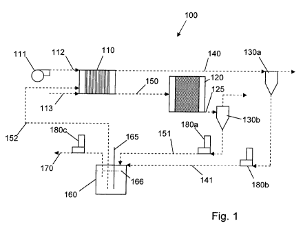
The fuel cell system 100, as shown in figure 1, comprises at least one fuel
cell
stack 110 and various connected components for the removal of water such as a
heat exchanger 120 and cyclonic water separators 130a, 130b on the anode and
cathode exit lines 140, 150 respectively. These components enable liquid water
to be recovered from the exit streams. The fluid stream passing through the
anode exit line 140 comprises water saturated hydrogen gas and liquid water
from the anode volume in the stack 110, while the fluid stream passing through
the cathode exit line 150 comprises water saturated air and liquid water from
the
cathode volume in the stack 110. The cathode exit stream passes into the heat
exchanger 120, which is designed to cool the cathode exit stream sufficiently
to
allow liquid water to be extracted. The extracted liquid water can then be
recirculated into the closed loop cooling circuit.
The fuel cell system is configured to capture a proportion of the water
discharged
into the cathode exhaust line 150 of the fuel cell stack 110 and recycle that
proportion for cooling and hydration of the membranes in the fuel cell stack.
The
proportion is controlled as a fraction of an operational parameter of the fuel
cell
stack, as further detailed below.
A closed loop cooling circuit in the fuel cell system shown in figure 1 can be
defined by the fuel cell stack 110, the cathode exit line 150, the heat
exchanger
120, the water separator 130b, a cathode water return line 151 leading to a
water
storage vessel 160 and a water injection line 152 leading back to the fuel
cell
stack 110. The water injection line 152 preferably leads to the cathode
volumes
5
CA 02741180 2011-04-19
WO 2010/049683 PCT/GB2009/002560
within the stack, where direct cooling can more effectively be achieved. The
closed loop circuit may also include the anode exit line 140, water separator
130a
and anode water return line 141, also leading to the water storage vessel 160.
Pumps 180a, 180b, 180c may be included in the cathode water return line 151,
anode water return line 141 and the water removal line 170 respectively, to
aid
the transport of water around and out of the cooling circuit. A further pump
(not
shown) is preferably included within the water storage vessel 160 for pumping
coolant water through the water injection line 152 into the fuel cell 110.
All the reaction water generated in the fuel cell stack 110 enters the closed
loop
cooling circuit, but not all of this water is passed on through the cathode
water
injection inlet line 152.
The water storage vessel 160 preferably comprises a level sensor 165 to
determine the level of water 166 within the vessel 160.
The water in the closed loop cooling circuit is controlled according to the
cooling
and humidification requirements of the fuel cell stack 110, with this
typically being
calculated in basic form as a function of the fuel cell stack 110 operating
current.
Excess water from the cooling circuit can be removed from the system through
the water removal line by means of the pump 180c.
It is to be understood that references to water throughout the specification
are
intended to encompass both liquid water and water vapour, unless the context
implies or specifies otherwise.
An air compressor 111 is arranged to force air into the cathode volume of the
fuel
cell stack 110 via a cathode air inlet 112. Fuel, in the form of hydrogen gas,
enters the anode volume of the fuel cell stack 110 via an anode inlet fine
113.
The exit temperature of the stream leaving the heat exchanger exit port 125 is
controlled such that sufficient liquid water is recovered to allow a suitable
level
166 within the water storage vessel 160 to be maintained. Typically, a
setpoint of
85% full is chosen for the level 166 in the water storage vessel 160, with the
remaining 15% used as a buffer to allow for hysteresis due to the thermal
inertia
of the heat exchanger 120. An amount of liquid water is therefore allowed to
flow
6
CA 02741180 2011-04-19
WO 2010/049683 PCT/GB2009/002560
through the cathode water return line 151 into the water storage vessel,
according to the chosen setpoint. Control of the system 100 is preferably set
such that the level 166 of water within the water storage vessel 160 is
maintained
irrespective of the water leaving the vessel through the water removal line
170.
However, if a setpoint level of, for example, 95% is chosen, the thermal
hysteresis as the heat exchanger cooling is reduced may be such that
additional
water will need be removed from the water storage vessel 160. If the thermal
characteristics of the heat exchanger 120 are known (either via calculation or
empirical methods), the amount of water removed from the water storage vessel
160 due to the overflow would also be known. Hence, it is possible to control
the
heat exchanger cooling such that a required amount of water is removed from
the
water storage vessel 160.
A more accurate means of removing liquid water from the storage vessel is by
use of a pump 180c. Such a pump may be either continually variable or of fixed
operation. If the pump 180c is continually variable according to a setpoint,
the
flow rate as a function of setpoint is obtained with the pump 180c providing
liquid
to the atmosphere via the water removal line 170. Thus, this data can be used
to
achieve a required flow rate by adjusting the setpoint accordingly. With a
fixed
operation pump, the flow rate of the pump is calibrated with it pumping water
to
atmosphere. This flow rate is thus the maximum that can be achieved. If a flow
rate below this maximum is required, the pump 180c can be switched on and off,
according to a suitable duty cycle. Typically, over a given time period, the
pump
180c will operate for a percentage of this time according to the ratio of the
required flow rate to the maximum. For example, if the pump 180c is calibrated
to
deliver 100 ml/min, and a flow rate of 25 ml/min is required, then the pump is
switched on for 15 seconds, and then off for 45 seconds, with this cycle
repeated
every 60 seconds. As well as increased accuracy, the use of a pump 180c to
remove the water has an additional benefit when the fuel cell system 100
comprises an air cooled heat exchanger 120. In this situation, the excess
water
from the water removal line 170 may be sprayed onto the heat exchanger 120 to
aid cooling, and thus allow the heat exchanger 120 to be smaller than would
otherwise be required to generate the liquid water for replenishing the
cooling
circuit.
7
CA 02741180 2011-04-19
WO 2010/049683 PCT/GB2009/002560
The amount of liquid water that should be added and removed from the closed
loop system can be calculated as a function of the total amount of water
generated due to the electrochemical reaction in the fuel cell stack 110. This
can
be calculated as follows.
Water production, WP = In moles s',
where I is the fuel cell stack current (in Amps), n is the number of cells in
the fuel
cell stack 110, and F is the Faraday constant (approximately 96.5 x 10³
Coulombs per mole). The above relationship assumes a stack of fuel cells
arranged electrically in series with each other, where the same current passes
through each cell.
The relative molecular mass of water is 18.0 g mole', and the density of water
is
0.998 g CM -3 at 20 C, hence:
Water production, WP = In x 60 x 18.1 ml min"'
The amount of liquid water to be removed from the cooling circuit, W, can be
expressed as,
W, _ /3 In moles s"' In x 60 x 18.1 ml min-'
2F 2F
or
W, _ /3WP
where /3 is the proportion of liquid water to be removed, as compared to the
total
amount of water generated by the fuel cell stack 110.
A preferred value for /3 is 0.1 as this provides an acceptable balance between
heat exchanger size and dilution of the liquid water within the closed loop,
although this value can be varied according to requirements. In general, the
amount of water to be removed for any given size of fuel cell can be described
as
being directly proportional to the fuel cell stack current.
8
CA 02741180 2011-04-19
WO 2010/049683 PCT/GB2009/002560
An alternative to the above approach is to measure the conductivity or other
operational parameter (e.g. pH, total dissolved solids, etc.) of the liquid
water
entering the fuel cell stack 110. The amount of water to be removed from the
system, and therefore the amount of liquid water to be drawn from the cathode
exit line 150, can be derived as a function of a calculated error between a
setpoint of conductivity or other parameter and the measured value. A standard
control loop (e.g. proportional, integral, derivative: PID) could be used for
this
purpose, with the control loop being set to allow for thermal inertia of the
:heat
exchanger 120.
The fuel cell system preferably comprises a suitable computerised controller
connected to the various relevant components of the fuel cell system 100. The
controller is configured to automatically determine the amount of water to be
removed from the closed loop cooling circuit as a function of a particular
operational parameter. For example, the controller can be configured to,
monitor
the current drawn from the stack 110, determine from this measurement the
amount of water to be removed from the closed loop cooling circuit, and adjust
operation of the pumps 180a, 180b, 180c accordingly. The controller may be
configured to control operation of the water separators 130a, 130b, and the
amount of water (if any) to be sprayed on to the heat exchanger 120 for
additional
cooling.
The controller may be configured to monitor operational parameters such as
water conductivity, pH or dissolved solids, and adjust the amount of liquid
water
removed from the cooling circuit accordingly. For example, if the conductivity
of
the liquid water within the cooling circuit rises, the controller may be
configured to
increase the amount of liquid water removed from and added to the cooling
circuit,
so as to dilute the cooling water with fresh water generated in the fuel cell
stack
110, and thereby reduce the conductivity of water in the cooling circuit.
Other embodiments are intentionally within the scope of the invention as
defined
by the appended claims.
9