Note: Descriptions are shown in the official language in which they were submitted.
CA 02741350 2011-04-20
=
1
DESCRI PTION
DEVICE FOR EXTINGUISHING FIRES
Object of the invention.
The present invention relates to a device for extinguishing fire of the type
used for supplying water for fire-fighting work outdoors and suitable for
being transported
by helicopter.
Background of the invention.
At present multiple devices intended for the transportation and use of
water for extinguishing fires are known, which devices store a considerable
amount of
water and are transported by vehicles, both by land and air to the fire area,
usually an
area exposed to the outside and of a certain extension, such as a forest fire,
industrial
facilities or a building of considerable size.
The use of a helicopter as a means of transport is a great advantage, as
the helicopter moves fast between the water loading point and the discharge
point into
the fire, it can carry a significant amount of water, it discharges accurately
and can also
load in tight spaces where seaplanes cannot land.
Some of the anti-fire and helicopter transported devices include a semi-
rigid open top reservoir provided with slings or cables for its suspended
fixation from a
helicopter and a lower discharge hatch, which can be operated by the pilot.
The loading
of this reservoir can be made at any pond and pool but the loading speed
depends on
the pilot's skill to achieve the immersion of the reservoir since the loading
is performed
through the top opening. Other disadvantages of these devices are: they
require that
the height of water in the loading area is higher than that of the reservoir
as the loading
is performed through its top, and that during transport part of the load may
be lost as the
reservoir is permanently opened at its top.
Other known devices include a rigid belly-tank, permanently installed on
the bottom of the helicopter and equipped with a hydraulic pump and a hose for
loading
said tank, while the unloading is done through hatches or trapdoors at the
bottom of the
tank. The helicopter equipped with this device is more stable in flight and
can reload in
shallow areas. However, the water loading by the hydraulic pump is slow and
the whole
AMENDED SHEET
CA 02741350 2013-11-13
'
28412-10
2
device is very heavy with respect to the water that it can carry.
In the patent RU 2197308 C2 an extinguishing fire apparatus from a
helicopter is described comprising a loading tank connected to a vacuum pump
which
carries out a suction of air inside the tank during the water loading
operation in order
to facilitate the filling thereof.
The patent application WO 2008/071825A2 describes a helibucket for
fire-fighting helicopters that has a flexible container provided with a
filling pump
equipped with level sensors for its automatic operation and stop when the
helibucket
touches the water, the unfolding of the helibucket and opening and closing of
the
loading hatches being performed by means of a system of cables.
This helibucket has maximum and minimum level sensors to control the
amount of water that is loaded.
Description of the invention
The device for extinguishing fires according to one aspect of the
invention, has special technical features intended to allow a fast loading of
the
reservoir through its lower end and to provide faster and versatile
performance of the
transportation of water used to extinguish fires.
This device is of the type comprising a rigid reservoir with connections
for coupling external hoses and fixing slings or cables to the bottom of a
helicopter for
the transportation of water or fire extinguisher liquids and their discharge
by opening
at least a lower hatch of the reservoir by control means operable from a
control
device, these control means being associated with pipes to the power
connections of
the helicopter's hydraulic system for driving the device, a vacuum pump
arranged in a
compartment of the helicopter and connected to the reservoir through a vacuum
line,
means to cause the opening of the lower hatch of the reservoir, means for
detecting
the filling of the reservoir comprising inner water level sensors connected to
a control
CA 02741350 2013-11-13
=
28412-10
2a
unit, and means for closing the lower hatch when said filling detection means
indicate
that the water loading has reached a pre-set level inside the reservoir.
According to an aspect of the invention the reservoir comprises a
vacuum sensor to regulate the vacuum created inside the reservoir by the
vacuum
pump when the reservoir is in the closed position and depending on the
quantity of
water to be loaded.
The means for opening a lower hatch comprise lower water sensors
= CA 02741350 2011-04-20
3
arranged outside, next to said lower hatch, and connected to a control unit
that causes
the opening of the lower hatch and the loading of water by the suction effect
produced
by the vacuum previously created inside the reservoir.
Thus,the helicopter pilot operates the vacuum pump on the way out to the
loading place in order to remove the air inside the reservoir in advance, and
when
he/she reaches the loading place, this vacuum or depression causes the filling
of the
reservoir without needing water pumps in a few seconds upon opening the lower
hatch
and raising the sucked up water.
In addition, the device comprises means for detecting when the reservoir
is full and means for automatically closing the lower hatch (21) when said
filling detection
means indicate that the water load has reached a pre-set level inside the
reservoir.
Suction through the inner hatch, while the reservoir is slightly submerged
below the surface of the water of the loading place, only requires a few
centimeters in
depth of said hatch to prevent entry of outside air. This load can be
performed
anywhere, whether a swimming pool, pond or river. By creating vacuum inside
the
reservoir, the load of water is faster and easier than through the use of
conventional
water moving pumps, or by the application of a vacuum during the loading
process, as
the vacuum sucks in a short time (about 6 to 12 seconds for 1200 liters) the
water that
the reservoir is able to hold. Also the discharge is immediate, since once
loaded the
reservoir the lower hatch closes automatically, leaving the device suitable
for allowing
such discharge by operating this lower hatch.
The tank is of rigid constitution and includes a top sealing hatch allowing,
after the loading, a better discharge of the water at the emptying place. The
reservoir
also has lower support elements that allow the support of the reservoir on a
surface
independently, the lower hatch being slightly higher with respect to the lower
part of said
support elements
This reservoir can be made of composites, polyester, steel, carbon fibre,
aluminium or other materials.
The vacuum pump is independent from the reservoir, preferably housable
in a compartment of the helicopter, which facilitates its maintenance and the
fact that
several reservoirs can be connected to the same transporting helicopter with
the vacuum
pump staying in the helicopter. Once the device loaded, the pilot should only
decide
whether to make a very fast, fast, medium, slow, etc. discharge, depending on
the
AMENDED SHEET
CA 02741350 2013-11-13
28412-10
4
instructions he/she receives.
In order to make the water loading operation as automatic and simple as
possible for the pilot it is provided that the control means, causing the
opening of the
lower hatch and the loading of water, include lower water sensors that
determine the
time of filling.
In turn, the means to detect the reservoir filling comprise sensors of the -
inside level of water, connected to a control unit for the water loading
operation. Once
these inner water level sensors detect that the reservoir has been filled, the
control unit
warns the pilot accordingly by means or acoustic and/or light warnings at the
cockpit
controls and the lower hatch closes to prevent loss of water. Then the upper
hatch
opens to allow the discharge when arriving at the spot where the reservoir
will be
emptied.
The reservoir can take different shapes, but it is mainly spherical or
cylindrical shaped with curved bases, as these are the structures which gives
the best
response to the inside vacuum when proceeding to the water loading. In these
cases,
the support elements comprise two parallel rigid rings connected by support
legs, the
upper ring being arranged above the middle of the reservoir and the lower
support ring
being larger.
The lower and/or upper hatches are of the butterfly type, driven by a
respective hydraulic cylinder by means of the power connections with the
helicopter.
However, it is possible that at least the upper hatch can be otherwise.
As mentioned above, the device reservoir can be placed on a solid
surface, such as ground, allowing it to be used for water supply in an area
more or less
close to the fire. Additionally the reservoir comprises connections for water
supply to
tankers, hoses and other fire-fighting equipment, either by hydraulic pumps or
simply by
gravity.
One of the objects of one aspect of the invention is to allow the device
to be quickly fitted or removed from the helicopter, preferably in less time
than half a
minute, comprising quick attachment means of the reservoir to the helicopter
for this
purpose. In one embodiment of the invention, these means are configured by a
plate
arranged on the bottom of the helicopter and equipped with vacuum connections
of hydraulic
pressure and power supply and another plate combined with means of quick
anchoring
to the helicopter plate, with the reservoir fixing slings and connections
being attached to
CA 02741350 2013-11-13
28412-10
said second plate, complementary to the first plate and connected to the
vacuum pipe
of the reservoir, to the hydraulic pressure pipes driving the reservoir
devices and to
the electric connections of the control unit and the control means.
In accordance with one aspect of the invention, there is provided a
5 device attached to a helicopter for extinguishing fires, comprising: a
rigid reservoir for
containing water, the reservoir including at least one connection for coupling
to at
least one external hose; fixing slings connected to the reservoir and to a
bottom
portion of the helicopter for facilitating transportation of the reservoir; a
lower hatch
located on a lower portion of the reservoir; hydraulic pipes connected to
power
connections of a hydraulic system of the helicopter; a control unit operably
connected
to a control device, wherein the control unit controls hydraulic pressure
within the
hydraulic pipes; a vacuum pump arranged in a compartment of the helicopter; a
vacuum line connected between the reservoir and the vacuum pump; means for
causing opening of the lower hatch to thereby facilitate filling of the
reservoir; means
for detecting a pre-set water level within the reservoir, comprising at least
one inner
water level sensor electrically connected to the control unit, wherein the
lower hatch
will automatically close when a water level of the reservoir has reached the
pre-set
water level; a vacuum sensor within the reservoir electrically connected to
the control
unit so as to provide information for regulating a vacuum created inside the
reservoir
by the vacuum pump when the reservoir is in a closed position and depending on
a
predetermined quantity of water to be loaded; wherein the means for causing
opening
of the lower hatch comprises at least one lower water sensor electrically
connected to
the control unit and arranged outside of an interior of the reservoir adjacent
to the
lower hatch for detecting the presence of water to be loaded; whereby water is
loaded into the reservoir through the lower hatch by a suction effect produced
by the
vacuum pump previously created inside the reservoir when the lower hatch is
opened.
CA 02741350 2013-11-13
28412-10
5a
Description of figures.
In order to complement the description that is being carried out and with
the purpose of facilitating the understanding of the characteristics of the.
invention, the
present description is accompanied by a set of drawings wherein, by Way of a
non-
limiting example, the following has been represented:
- Figure 1 shows an elevation view of one embodiment of the device for
extinguishing fires attached to a helicopter.
- Figure 2 shows a block diagram of the control means of the device.
- Figure 3 shows an elevation view of the section of the reservoir and
inside components.
- Figure 4 shows a detail of a schematic embodiment of the coupling
means.
Preferred embodiment of the invention
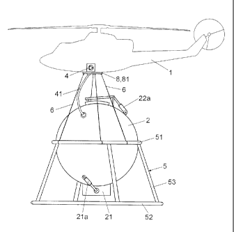
As can be seen in the referenced figures, the device for extinguishing fires
can be coupled on the bottom of a helicopter (1) for its operation and
transportation of
water from the loading areas to the point where its use is necessary.
Thus, the device comprises a reservoir (2) of rigid and watertight
constitution, in this case spherical shaped and made of plastic, which has a
jower hatch
(21) of butterfly type and a sealing articulated upper hatch (22) both hatches
being
driven by hydraulic cylinders (21a and 22a) connected by pipes (3) to the
hydraulic
power connections of the helicopter (1). The device comprises a vacuum pump
(4),
housed in the helicopter (1) and connected by a vacuum pipe (41) to the
reservoir (2).
The reservoir (2) presents at its bottom supporting elements (5) that
define a .support such that the lower hatch (21) is just a few centimetres
above the
surface on which it rests, these supporting elements (5) being made up of two
parallel
rigid rings (51 and 52) joined by legs (53), the first upper ring (51) is
arranged around the
middle of the spherical reservoir (2) and from which the legs (53) extend
downwards
diverging to the lower ring (52), which has a larger diameter to allow better
stability of the
CA 02741350 2011-04-20
6
reservoir (2) resting on the ground.
In the upper ring (51) are fixed slings (6) for fixing to the bottom of the
helicopter (1), what allows the transportation of the suspended reservoir.
The device has means for its operational control that are set by a control
unit (71) for the automatic working of certain operations, with said control
unit (71) being
associated to actioning controls (72) at the cockpit and water lower sensors
(73) next to
the lower hatch (21) and inside water level sensors (74) in the reservoir (2)
to check the
load. The control means also comprise a vacuum sensor (75) inside the
reservoir -(2)
Figure 4 shows a detail of a quick coupling means for attaching the device
to the helicopter (1), said quick coupling means being configured by a plate
(8) fixed at
the bottom of the helicopter (1) and another combined plate (81), which in
this case has
a few direct coupling hooks (82) on the sides, with the corresponding
connections of the
fixing slings (6), the vacuum pipe (41) between the vacuum pump (4) and the
reservoir
(2), the pipes (3) with hydraulic power connections and electrical connections
(76) of the
sensors (73, 74 and 75) from inside the helicopter (1) being associated with
said plate
(81).
Figure 3 shows the reservoir (2) having at its bottom connections (23) for
coupling hoses.
Once the nature of the invention as well as an example of preferred
embodiment have been sufficiently described, it is stated for all pertinent
purposes that
the materials, form, size and arrangement of the elements described are
susceptible to
changes, provided these do not involve an alteration of the essential
characteristics of
the invention that are claimed subsequently.
AMENDED SHEET