Note: Descriptions are shown in the official language in which they were submitted.
CA 02741389 2011-05-30
{DESCRIPTION}
{Title of Invention}
CONTROLLER FOR WIND TURBINE GENERATOR, WIND TURBINE GENERATOR,
AND METHOD OF CONTROLLING WIND TURBINE GENERATOR
{Technical Field}
{0001}
The present invention relates to a controller for a wind
turbine generator, a wind turbine generator, and a method of
controlling a wind turbine generator.
{Background Art}
{0002}
In a wind turbine generator, a rotor having blades
rotates due to being struck by wind, and a generator coupled
to the rotor via a main shaft generates electricity based on
the rotation of the rotor. Due to the rotation of the rotor,
a load according to the rotation acts on devices such as the
main shaft and gear box of the wind turbine generator. For
this reason, in order to prevent the load acting on devices
such as the main shaft and gear box from exceeding a
determined design load in the wind turbine generator,
generation of electricity is stopped when speed of wind
reaches a predetermined wind speed (cut-out wind speed).
{0003}
PTL 1 discloses technology for reducing power by lowering
the rotational speed of the rotor if the wind striking the
CA 02741389 2011-05-30
2
wind turbine generator has reached a wind speed that causes
wear due to overload.
{Citation List}
{Patent Literature}
{0004}
{PTL 1}
EP Patent No. 0847496
{Summary of Invention}
{Technical Problem}
{0005}
However, in the technology disclosed in PTL 1, although
the load acting on devices can be reduced when the wind is
strong, the power is accordingly reduced, and therefore the
total amount of electricity generated per year decreases as
the frequency with which a strong wind blows increases.
{0006}
The present invention has been achieved in light of such
a situation, and an object thereof is to provide a controller
for a wind turbine generator, a wind turbine generator, and a
method of controlling a wind turbine generator that can reduce
the 'Load acting on a device and suppress a reduction in power
even in the case where the blades are struck by strong wind.
{Solution to Problem}
{0007}
In order to solve the above-described problems, a
CA 02741389 2011-05-30
3
controller for a wind turbine generator, a wind turbine
generator, and a method of controlling a wind turbine
generator of the present invention employ the following
solutions.
{0008}
Specifically, a controller for a wind turbine generator
according to the present invention is a controller for a wind
turbine generator in which a rotor having a blade rotates due
to being struck by wind, and a generator coupled to the rotor
via a main shaft generates electricity based on the rotation
of the rotor, the controller including: a power control unit
that, in a case where the blade has been struck by wind that
has reached a predetermined second wind speed that is lower
than a first wind speed at which torque acting on the main
shaft reaches a limit value at which the possibility of
causing wear in a device exists, performs control for causing
change in the torque when wind speed is higher than the second
wind speed to be different from change in the torque when wind
speed is lower than the second wind speed so as to prevent the
torque from exceeding the limit value at the first wind speed.
{0009)
According to the present invention, in a wind turbine
generator in which a rotor having blades rotates due to being
struck by wind, and a generator coupled to the rotor via a
main shaft generates electricity based on the rotation of the
CA 02741389 2011-05-30
4
rotor, the torque acting on the main shaft is controlled.
Note that the torque acting on the main shaft increases
as the speed of wind striking the blades increases, and the
torque has a limit value at which there is the possibility of
causing wear in a device. Besides the main shaft, examples of
the above-described device include a gear box.
{0010}
In view of this, in the case where the blades have been
struck by wind that has reached the predetermined second wind
speed that is lower than the first wind speed at which the
torque acting on the main shaft reaches the limit value, the
power control unit performs control for causing change in the
torque when wind speed is higher than the first wind speed to
be different from change in the torque when wind speed is
lower than the second wind speed so as to prevent the torque
from exceeding the limit value at the first wind speed.
{0011
Conventionally, in the case where the blades are struck
by wind whose wind speed is the first wind speed at which the
torque exceeds the limit value, the generation of energy by
the generator is stopped in order to prevent wear in a device,
but in the present invention, the control performed by the
power control unit enables continuing the generation of energy
by the generator even if the first wind speed is exceeded.
{0012}
CA 02741389 2011-05-30
Accordingly, the present invention can reduce the load
acting on a device and suppress a reduction in power even if
the blades are struck by strong wind.
{0013}
Also, a controller for a wind turbine generator according
to the present invention is a controller for a wind turbine
generator in which a rotor having a blade rotates due to being
struck by wind, and a generator coupled to the rotor via a
main shaft generates electricity based on the rotation of the
rotor, the controller including: a power control unit that, in
a case where the blade has been struck by wind that has
reached a first wind speed at which torque acting on the main
shaft reaches a limit value at which the possibility of
causing wear in a device exists, performs control for causing
change in the torque when wind speed is higher than the first
wind speed to be different from chance in the torque when wind
speed is lower than the first wind speed so as to prevent the
torque from exceeding the limit value at the first wind speed.
{0014}
In the present invention, in the case where the blades
have been struck by wind that has reached the first wind speed
at which the torque acting on the main shaft reaches the limit
value, the power control unit performs control for causing
change in the torque when wind speed is higher than the first
wind speed to be different from change in the torque when wind
CA 02741389 2011-05-30
6
speed is lower than the first wind speed so as to prevent the
torque from exceeding the limit value at the first wind speed.
Accordingly, the present invention can reduce the load
acting on a device and suppress a reduction in power even if
the blades are struck by strong wind.
{0015}
Also, in the above-described configuration, it is
preferable that the controller for a wind turbine generator
includes: a pitch angle control unit that, in a case where the
control is being performed by the power control unit, controls
a pitch angle of the blade so as to keep a rotational speed of
the rotor constant.
{0016}
When the power control unit performs the above-described
control, the rotation of the rotor speeds up due to the
reduction of the load on the generator. For this reason,
rotor control needs to be performed along with the above-
described control in the wind turbine generator. In view of
this, according to the present invention, in the case where
the above-described control has been performed by the power
control unit, the pitch angle of the blades is controlled such
that the rotor rotational speed is kept constant (e.g.,
constant at the rated rotational speed), thus enabling
preventing a rise in the rotor rotational speed.
(0017)
CA 02741389 2011-05-30
7
Also, in the above-described configuration, it is
preferable that in a case where wind striking the blade
reaches the second wind speed, the power control unit sets a
slope of change in the torque lower than that before wind
speed reaches the second wind speed.
{0018}
According to the present invention, in the case where the
wind striking the blades reaches the second wind speed, the
slope of change in the torque acting on the main shaft is set
lower than that before the second wind speed is reached, thus
enabling more reliably preventing the torque from exceeding
the limit value at the first wind speed.
{0019}
Also, in the above-described configuration, it is
preferable that in a case where wind striking the blade
reaches the first wind speed, the power control unit lowers
the torque by a predetermined amount, and thereafter increases
the torque according to increase in wind speed.
{0020}
According to the present invention, in the case where the
wind striking the blades reaches the first wind speed, the
torque acting on the main shaft is lowered by a predetermined
amount, and thereafter the torque is increased according to
the increase in wind speed, thus enabling obtaining more power
from the generator.
CA 02741389 2011-05-30
8
{0021}
Furthermore, a wind turbine generator according to the
present invention includes: a rotor that has a blade and
rotates due to being struck by wind; a generator that is
coupled to the rotor via a main shaft and generates
electricity based on the rotation of the rotor; and the
controller according to a configuration described above.
{0022}
The present invention enables reducing the load acting on
a device and suppressing a reduction in power even if the
blades are struck by strong wind.
{0023}
Also, a method of controlling a wind turbine generator
according to the present invention is a method of controlling
a wind turbine generator in which a rotor having a blade
rotates due to being struck by wind, and a generator coupled
to the rotor via a main shaft generates electricity based on
the rotation of the rotor, the method including: a first step
of, in a case where the blade has been struck by wind that has
reached a predetermined second wind speed that is lower than a
first wind speed at which torque acting on the main shaft
reaches a limit value at which the possibility of causing wear
in a device exists, performing control for causing change in
the torque when wind speed is higher than the second wind
speed to be different from change in the torque when wind
CA 02741389 2011-05-30
9
speed is lower than the second wind speed so as to prevent the
torque from exceeding the limit value at the first wind speed;
and a second step of stopping generation of electricity
performed by the generator in a case where the wind speed
increases further and reaches a third wind speed at which the
torque reaches the limit value.
{0024}
The present invention enables reducing the load acting on
a device and suppressing a reduction in power even if the
blades are struck by strong wind.
{0025}
Also, a method of controlling a wind turbine generator
according to the present invention is a method of controlling
a wind turbine generator in which a rotor having a blade
rotates due to being struck by wind, and a generator coupled
to the rotor via a main shaft generates electricity based on
the rotation of the rotor, the method including: a first step
of, in a case where the blade has been struck by wind that has
reached a first wind speed at which torque acting on the main
shaft reaches a limit value at which the possibility of
causing wear in a device exists, performing control for
causing change in the torque when wind speed is higher than
the first wind speed to be different from change in the torque
when wind speed is lower than the first wind speed so as to
prevent the torque from exceeding the limit value at the first
CA 02741389 2011-05-30
wind speed; and a second step of stopping generation of
electricity performed by the generator in a case where the
wind speed increases further and reaches a third wind speed at
which the torque reaches the limit value.
{0026}
The present invention enables reducing the load acting on
a device and suppressing a reduction in power even if the
blades are struck by strong wind.
{Advantageous Effects of invention}
0027}
The present invention. causes a super-or effect of
enabling reducing the load acting on a device and suppressing
a reduction in power even if the blades are struck by strong
wind.
{Brief Description of Drawings}
{0028}
{Fig. 1} Fig. 1 is an external view of a wind turbine
generator according to a first embodiment.
{Fig. 2} Fig. 2 is a diagram showing an electrical
configuration of the wind turbine generator according to the
first embodiment.
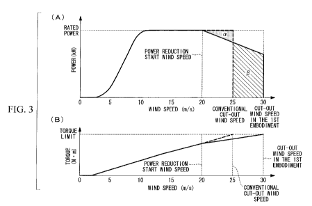
{Fig. 3} Figs. 3(A) and 3(B) are graphs showing types of
change with respect to wind speed in the wind turbine
generator according to the first embodiment, where Fig. 3(A)
shows change in power of the wind turbine generator with
CA 02741389 2011-05-30
ll
respect to wind speed, and Fig. 3(B) shows change in torque
acting on a main shaft with respect to wind speed.
{Fig. 4} Figs. 4(A) and 4(B) are graphs showing types of
change with respect to wind speed in the wind turbine
generator according to the first embodiment, where Fig. 4(A)
shows change in rotor rotational speed with respect to wind
speed, and Fig. 4(B) shows change in blade pitch angle with
respect to wind speed.
(Fig. 5} Fig. 5 is a flowchart showing a flow of torque
reduction control processing including control with respect to
pitch angle according to the first embodiment.
{Fig. 6} Figs. 6(A) and 6(B) are graphs showing types of
change with respect to.wind speed in a wind turbine generator
according to a second embodiment, where Fig. 6(A) shows change
in the power of the wind turbine generator with respect to
wind speed, and Fig. 6(B) shows change in torque acting on a
main shaft with respect to wind speed.
(Description of Embodiments}
{0029}
Below is a description of embodiments of a controller for
a wind turbine generator, a wind turbine generator, and a
method of controlling a wind turbine generator according to
the present invention, with reference to the drawings.
{0030}
The following describes a first embodiment of the present
CA 02741389 2011-05-30
12
invention.
Fig. 1 is an external view of a wind turbine generator 10
according to the first embodiment.
The wind turbine generator 10 shown in Fig. 1 is a so-
called variable-speed wind turbine and has a tower 14 provided
upright on a foundation 12, a nacelle 16 disposed on the upper
end of the tower 14, and a rotor 18 provided on the nacelle 16
so as to be able to rotate around a substantially horizontal
axis.
{0031}
A plurality of blades 20 (e.g., three in the first
embodiment) are attached to the rotor 18 in a radial
configuration around the rotation shaft line of the rotor 18.
Accordingly, the force of wind striking the blades 20 from the
rotation shaft line direction of the rotor 18 is converted
into driving force that causes the rotor 18 to ror_ate around
the rotation shaft line. This driving force is converted into
power by a generator 34 (see Fig. 2) coupled to the rotor 18
via a main shaft 30. Note that the blades 20 are coupled to
the rotor 18 so as to be able to rotate in accordance with an
operating condition, and the pitch angle of the blades 20 is
variable.
The generator 34 includes a power converter configured by
an inverter, a converter, and the like, and the power
converter converts AC power output by the generator 34 into AC
CA 02741389 2011-05-30
13
power suited to the frequency of a power system.
{0032}
Fig. 2 is a schematic diagram showing an electrical
configuration of the wind turbine generator 10 according to
the first embodiment.
{0033}
In the wind turbine generator 10, driving force is
transmitted to the generator 34 via a gear box 32 that
accelerates the rotational speed of the main shaft 30, and the
generator 34 converts the driving force into power.
The wind turbine generator 10 is electrically connected
to the power system (Grid) via a transformer 36, and the wind
turbine generator 10 supplies the power converted from driving
force by the generator 34 to the power system.
{0034}
The wind turbine generator 10 is controlled by a wind
turbine controller 40 located inside of the nacelle 16.
The wind turbine controller 40 includes a generator power
control unit 42 and a pitch angle control unit 44.
{0035}
The generator power control unit 42 generates a power
command value Pdem for controlling the power of the generator
34, and outputs the power command value Pdem to the generator
34. The power command value Pdem is determined based on, for
example, a power request from the power system, the current
CA 02741389 2011-05-30
14
power of the generator 34, the rotational speed of the rotor
18, the pitch angle of the blades 20, and the wind speed.
Upon receiving the power command value Pdem, the
generator 34 changes the power based on the power command
value Pdem.
{0036}
The pitch angle control unit 44 generates a pitch angle
command value 9 for controlling the pitch angle of the blades
20, and transmits the pitch angle command value 9 to a pitch
actuator (not shown) for changing the pitch angle, which is
included in the rotor 18. The pitc, angle command value 0 is
determined based on, for example, the current pitch angle, the
speed of wind striking the blades 20, and the rotational speed
of the rotor 18.
Upon receiving the pitch angle command value 9, the pitch
actuator changes the pitch angle of the blades 20 based on the
pitch angle command value 9.
{0037}
rigs. 3(A) and 3(B) are graphs showing types of change
with respect to wind speed in the wind turbine generator 10
according to the first embodiment. in the following
description, "wind speed" refers to mean wind speed (e.g., the
mean over 10 minutes).
(0038}
Fig. 3(A) is a graph showing change in the power of the
CA 02741389 2011-05-30
wind turbine generator 10 with respect to wind speed. In Fig.
3(A), the solid line indicates change in the power of the wind
turbine generator 10 of the first embodiment with respect to
wind speed, and the broken line indicates change in the power
of a conventional wind turbine generator with respect to wind
speed.
0039
Fig. 3(B) shows change in the torque acting on the main
shaft 30 with respect to wind speed. Note that in Fig. 3(B),
she solid line indicates change in the torque of the wind
turbine generator 10 of the first embodiment w_ t_h respect to
wind speed, and the broken line indicates change in the torque
of a conventional wind turbine generator with respect to wind
speed. It should also be noted that although the solid line
and the broken line shown in Fig. 3(B) change linearly due to
being planning lines, in actuality variation occurs.
(00401
As shown in Fig. 3(A), the power generated by the
generator 34 in the wino turbine generator 1C increases as the
wind speed increases. Upon reaching the rated power, the
power generated by the generator 34 is kept at the rated
power.
In the conventional wind turbine generator, when the wind
striking the blades 20 reaches a predetermined wind speed
(e.g., 25 m/s, which is hereinafter referred to as the "cut-
CA 02741389 2011-05-30
16
out wind speed") while the power generated by generator is
kept at the rated power, the wind turbine controller 40
outputs a power command value Pdem for setting the power to 0
kW, and generation of electricity is stopped as shown by the
broken line Fig. 3(A).
{0041}
The load (torque) acting on the main shaft 30 increases
as the wind speed increases, and thus the above is performed
in order to prevent this load from exceeding the designed
load.
in view of this, the cut-out wind speed at which
generation of electricity performed by the wind turbine
generator 10 is stopped is, as shown in Fig. 3(B), set to a
wind speed at which the torque acting on the main shaft 30 due
to wind reaches a limit value (hereinafter, referred to as the
"torque limit") at which there is the possibility of causing
wear in a device (the main shaft 30, the gear box 34, or the
like).
{0042}
However, there is demand for obtaining more amount of
electricity (total amount of generation of electricity per
year) from the wind turbine generator 10, and as one method of
obtaining more amount of generation of electricity, it is
conceivable to set the cut-out wind speed, at which the wind
turbine generator 10 is stopped, to a wind speed that is
CA 02741389 2011-05-30
17
higher than the conventional cut-out wind speed.
{0043}
In view of this, in the wind turbine generator 10
according to the first embodiment, if the blades 20 have been
struck by wind that has reached a predetermined wind speed
(hereinafter, referred to as the "power reduction start wind
speed") that is lower than the conventional cut-out wind
speed, control (hereinafter, referred to as "torque reduction
control") s i performed for causing the change in torque when
wind speed is higher than the power reduction start wind speed
to be dafferenit from change the torque when wind speed as
lower than the power reduction start wind speed so as to
prevent the torque from exceeding the torque limit value at
the conventional cut-out wind speed.
In other words, the wind turbine generator 10 performs
control for reducing (suppressing) an increase in torque with
respect to an increase in wind speed, in a wind speed region
that is higher than the rated wind speed and furthermore lower
than the cut-out wind speed. Note that the power reduction
start wind speed is included in this wind speed region.
{0044}
Specifically, with the wind turbine generator 10 of the
first embodiment, when the wind striking the blades 20 reaches
the power reduction start wind speed, the slope of the change
in torque is set smaller than that in the case of a wind speed
CA 02741389 2011-05-30
18
lower than the power reduction start wind speed, as shown by
the solid line in Fig. 3(B). Accordingly, when the wind
striking the blades 20 reaches the power reduction start wind
speed, and torque reduction control is performed, the power of
the wind turbine generator 10 begins to be reduced so as to be
lower than or equal to the rated power, as shown by the solid
line in Fig. 3 (A) .
(0045}
Also, as shown by the solid line in Fig. 3(B), due to
performing torque reduction conr_rol, the torque does not reach
the torque limit even at a Wind speed higher than the
conventional cut-out wind speed. For this reason, even if the
wind striking the blades 20 reaches a wind speed exceeding the
conventional cut-out wind speed, the power of the wind turbine
generator 10 falls to a power less than or equal to the rated
power, but generation of electricity can be continued, and it
is possible to obtain more amount of electricity than a
conventional wind turbine generator.
{0046}
Note that if the wind speed has reached the power
reduction start wind speed, the generator power control unit
42 transmits, to the generator 34, a power command value Pdem
for reducing the power of the generator 34. Upon receiving
the power command value Pdem, the generator 34 reduces the
magnitude of the torque by controlling the magnitude of the
CA 02741389 2011-05-30
19
magnetic field generated by the field system, in accordance
with the power command value Pdem.
{0047)
Here, the power reduction start wind speed need only be a
wind speed lower than the conventional cut-out wind speed. As
one example, if the conventional cut-out wind speed is 25 m/s,
the power reduction start wind speed is 20 m/s.
The reason for this is that wind speed always has a
certain degree of fluctuation range, and in the exemplary case
where the wind speed is 25 m/s, the fluctuation range thereof
is approximately a wind speed m/s in the low tens to a wind
speed m/s in the low twenties, and therefore the torque acting
on the main shaft 30 is prevented from exceeding the torque
limit in the case where the instantaneous peak wind speed
exceeds the conventional cut-out wind speed before torque
reduction control is performed.
{00481
Also, with the wind turbine generator 10 of the first
embodiment, the power is reduced so as to be lower than the
rated power if the power reduction start wind speed has been
reached, and therefore power corresponding to the region a in
Fig. 3(A) is not generated, unlike the conventional wind
turbine generator. However, with the wind turbine generator
of the first embodiment, the amount of power corresponding
to the region (3 obtained by generation of electricity
CA 02741389 2011-05-30
performed at a wind speed higher than the conventional cut-out
wind speed is greater than the amount of power corresponding
to the region e. For this reason, the wind turbine generator
10 of the first embodiment can obtain more amount of
electricity than the conventional wind turbine generator.
{0049}
Fig. 4(A) shows change in the rotational speed of the
rotor 18 with respect to wind speed ir_ the first embodiment,
and Fig. 4 1~ ~ of ,3) shows change in the pitch angle o~ e blades
n the , 20
w~th respect to wind speed. In Fig. 4(3), the solid line
-ndicates chongc in pitch angle i-. _`- .,t embodiment with
respect to wind speed, and `he or,ken cafes
.~ :G
conventional change in pitch angle with respect to wind speed.
(0050}
As shown in Fig. 4(A), the wind turbine generator 10 of
the first embodiment controls the pitch angle of the blades 20
so as to keep the rotational speed of the rotor 18 constant
irrespective of whether or not torque reduction control is
performed. Note that as one example in the first embodiment,
the rotational speed of the rotor 18 is kept at the rated
rotational speed.
{0051)
Next is a description of the flow of torque reduction
control processing, which includes control with respect to the
pitch angle, performed by the wind turbine controller 40 of
CA 02741389 2011-05-30
21
the first embodiment, with reference to the flowchart shown in
Fig. S. Note that the torque reduction control processing is
started when the wind speed of wind striking the blades 20
reaches the power reduction wind speed.
{0052}
First, in step 100, the wind turbine controller 40 causes
the generator power control unit 42 to output a power command
value Pdem for reducing the power of the generator 34, as
described above.
Accordingly, the torque acting on the ma _.n shaft 30 1s
reduced, cud the load on the generator 34 decrea.se and taus
the rotational speed ..f t._. rotor 8 rises. however spice
the rotational speed of the rotor 18 has already reached the
rated rotational speed, it is not preferable that the
rotational speed of the rotor 18 increases any further.
{0053}
ln. view of this, in step 5102, the rotational speed of
the rotor 18 is prevented from exceeding the rated rotational
speed, and the rotational speed is kept constant at the rated
rotational speed. In order to achieve this, the wind turbine
controller 40 causes the pitch angle control unit 44 to
transmit, to the pitch actuator, a pitch angle command value 0
for changing the pitch angle so as to be more toward the
feathering side than the conventional pitch angle, as shown by
the solid line in Fig. 4(B).
CA 02741389 2011-05-30
22
Upon receiving the pitch angle command value e, the pitch
actuator changes the pitch angle so as to be more toward the
feathering side in accordance with the pitch angle command
value e, that is to say, decreases the pitch.
In this way, the wind turbine generator 10 of the first
embodiment keeps the rotational speed of the rotor 18 at the
rated rotational speed, thus enabling keeping the inertial
force of the rotor 18 high and preventing an increase in
torque.
;0054}
in the next step 104, the wind speed increases further,
determination is made as to whether the wind speed has Leached
the cut-out wind speed (e.g., 30 m/s) of the first embodiment,
the processing moves to step 106 in the case of an affirmative
determination, and the processing moves to step 108 in the
case of a negative determination. Note that the cut-out wind
speed of the first embodiment is a wind speed higher than the
conventional cut-out wind speed, and is a wind speed at which
the torque acting on the main shaft 30 reaches the torque
limit in the case where torque reduction control is being
performed.
{0055}
In step 106, the wind turbine controller 40 transmits, to
the generator 34, a power command value Pdem for causing the
generator power control unit 42 to stop generation of
CA 02741389 2011-05-30
23
electricity. Upon receiving the power command value Pdem, the
generator 34 stops generation of electricity, and torque
reduction control is ended.
{0056}
Along with this, the pitch angle control unit 44 may
transmit, to the pitch actuator, a pitch angle command value 0
for changing the pitch angle so as to be completely on the
feathering side in order to cause the blades 20 to allow the
wind to pass and stop the rotation of the rotor 18. Upon
receiving the pitch angle command value 8, the pitch actuator
changes the pitch angle to th-e Leathers' g side in accordance
w.L _h the p t ch ang,
e-, N comma nd vague ~ .
{0057}
On the other hand, in step 108, a determination is made
as to whether the wind striking the blades 20 is less than or
equal to the power reduction start wind speed, the processing
moves to step 110 in the case of an affirmative determination,
and the processing moves to step 104 in the case of a negative
determination.
{0058}
In step 110, the wind turbine controller 40 transmits, to
the generator 34, a power command value Pdem for causing the
generator power control unit 42 to raise the power to the
rated power.
{0059}
CA 02741389 2011-05-30
24
Next, in step 112, the wind turbine controller 40 causes
the pitch angle control unit 44 to transmit, to the pitch
actuator, a pitch angle command value 0 in the case where
torque reduction control is not performed, and torque
reduction control is ended.
{0060}
As described above, with the wind turbine generator 10 of
the first embodiment, if the blades 20 have been struck by
wind that has reached a power reduction start wind speed that
is lower than a conventional cut-out wind speed at which the
torque acting the main shaft 30 reaches the torque limit,
torque reduction control is performed for causing change in
the torque when wind speed is higher than the power reduction
start wind speed to be different from change in the torque
when wind speed is lower than the power reduction start wind
speed so as to prevent the torque from exceeding the torque
limit value at the conventional cut-out wind speed.
{0061}
Specifically, with the wind turbine generator 10 of the
first embodiment, if the wind striking the blades 20 reaches
the power reduction start wind speed, the slope of change in
the torque with respect to wind speed is set smaller than that
before the power reduction start wind speed is reached.
{0062}
After torque reduction control has started, if the wind
CA 02741389 2011-05-30
speed increases further and reaches a wind speed at which the
torque reaches the torque limit, the wind turbine generator 10
stops the generation of electricity performed by the generator
34.
{0063
Accordingly, the wind turbine generator 10 of the first
embodiment can reduce the load acting on a device and suppress
a reduction: in power even if the blades 20 are struck. by
strong wind. Furthermore, since the wind turbine generator 10
of t e floss embodiment ca:1 reduce the load acting on a
device, device maxi 7 'cad ash 'n-' ue
_ sere t Ve r
leeway.
{0064}
Note that with the wind turbine generator 10 of the first
embodiment, if torque reduction control is being performed,
the pitch angle of the blades 20 is controlled so as to keep
the rotational speed of the rotor 18 constant, thus enabling
preventing the rotational speed of the rotor 18 from
increasing.
{0065}
Second Embodiment
The following describes a second embodiment of the
present invention.
{0066}
Note that the configuration. of a wind turbine generator
CA 02741389 2011-05-30
26
of the second embodiment is similar to the configuration of
the wind turbine generator 10 of the first embodiment shown in
Figs. 1 and 2, and therefore a description of the
configuration has been omitted.
{0067}
Figs. 6(A) and 6(B) are graphs showing types of change
with respect to wind speed in the wind turbine generator 10
according to the second embodiment, where Fig. 6(A) shows
change in the power of the wind turbine generator 10 with
respect to wind speed, and F g 6(B) shows charge in torque
speed, -:am
ac _ g on the main shaft 30 with re oect to w, na steed.
0060 }
If the wind striking the blades 20 reaches the
conventional cut-out wind speed as shown in Fig. 6(B), the
generator power control unit 42 of the wind turbine generator
10 of the second embodiment lowers the torque by a
predetermined amount, and thereafter performs torque reduction
control for increasing the torque in accordance with increase
in the wind speed.
In order to perform such torque reduction control, if the
wind striking the blades 20 reaches the conventional cut-out
wind speed, the generator power control unit 42 outputs, to
the generator 34, a power command value Pdem for steeply
reducing the power of the generator 34 by a predetermined
amount. Thereafter, the generator power control unit 42
CA 02741389 2011-05-30
27
outputs, to the generator 34, a power command value Pdem for
gradually reducing the power.
{0069}
Accordingly, with the wind turbine generator 10 of the
second embodiment, as shown in Fig. 6(A), there is no decrease
in generation of electricity corresponding to the region a
shown in Fig. 3(A) of the first embodiment, thus enabling
obtaining more power from the generator 34.
{0070)
Note that also in the wind tsrbine generator 10 of the
second embodiment, torque reduction control performed in
order to reduce the torque acting on the main shaft 30 and
reduce the load on the generator 34, and thus the rotational
speed of the rotor 18 increases. In view of this, the pitch
angle control unit 44 of the second embodiment transmits, to
the pitch actuator, a pitch angle command value e for changing
the pitch angle so as to be more toward the feathering side
than the conventional pitch angle, as in the first embodiment.
Upon receiving the pitch angle command value e, the pitch
actuator changes the pitch angle toward the feathering side in
accordance with the pitch angle command value e, that is to
say, decreases the pitch. Accordingly, the wind turbine
generator 10 of the second embodiment keeps the rotational
speed of the rotor 18 at the rated rotational speed, thus
enabling keeping the inertial force of the rotor 18 high and
CA 02741389 2011-05-30
28
preventing an increase in torque.
{00711
If the wind striking the blades 20 then reaches the cut-
out wind speed of the second embodiment, which is higher than
the conventional cut-out wind speed, the wind turbine
generator 10 stops generation of electricity performed by the
generator 34.
{00721
Although the present invention has been described using
the above embodiments, the technical scope of the present
_"lv2n~ieC '. to the scope disclosed in the above
~m^_ is not ~--__~ ~ embodiments. Various variations and modifications can be
made
to the above embodiments without departing from the spirit of
the invention, and all such variations and modifications are
also encompassed in the technical scope of the present
invention.
10073}
For example, although a configuration in which torque
reduction control is performed only one time after the wind
speed has reached the power reduction start wind speed is
described in the first embodiment (after the wind speed has
reached the conventional cut-out wind speed in the second
embodiment), the present invention is not limited to this, and
a configuration is possible in which torque reduction control
is performed a plurality of times before the torque reaches
CA 02741389 2011-05-30
29
the torque limit.
{0074}
Also, although a configuration in which the torque is
changed linearly after torque reduction control is described
in the above embodiments, the present invention is not limited
to this, and, for example, the torque may be changed
curvilinearly so as to be asymptotic to the torque limit, or
the torque may be changed gradually in a stepwise fashion.
{Reference Signs List;
{0075}
0 wi.' _.hrh in r'.o ne or
13 rotor
20 blade
30 main shaft
40 w;nd turbine controller
42 generator power control unit
44 pitch angle control unit