Note: Descriptions are shown in the official language in which they were submitted.
CA 02741531 2011-06-27
1
LAB EcLaR
BACKGROUND OF THE INVENTION
[00011 The present invention is directed to a labeller for applying labels to
products, and more particularly to a labeller for indexing labels from a label
web and tamping
the labels onto the products.
[0002] Labellers arc well known for applying labels to items such as fruits,
vegetables or other consumer goods. These devices typically include a label
wheel that
receives and holds a roll of label web, including a plurality of labels
supported sequentially
on a release liner. The label web is advanced from the wheel through the
labeler to an edge,
typically called a peel plate. The web is pulled over the edge of the peel
plate to separate the
labels from the support liner, allowing the labels to be deposited onto the
items.
[0003] Many labellers include a tamping mechanism that can extend to
deposit a label onto an item. For instance, it is common for labellers to
include one or more
tamping bellows, which include a tamping face in communication with a vacuum
source and
a positive pressure source, and are moveable between a retracted position and
an extended
tamping position. The tamping face of the bellows may be moved to a position
adjacent to
the peel plate to receive a label as the label web is indexed over the peel
plate. The tamping
bellows may then carry the label, using the vacuum source to hold the label on
the tamping
face, to a position in which the bellows communicates with a positive pressure
source to
extend the bellows and tamp the label onto an item to be labeled.
[0004] Although prior art labellers are generally acceptable, problems arise
in
a number of aspects of these labellers. For instance, difficulties arise with
the release liner
after the labels have been removed. The amount of this waste release liner
continues to grow
as additional labels are deposited onto items, creating a messy "tail" of
release liner that can
obstruct the user and the labeller until the user tears off or moves the tail
¨ only to have the
tail quickly grow back again.
CA 02741531 2011-06-27
2
[0005] Additional problems with prior art label webs include the replacement
of label webs for labelling different types of products. In most cases, the
labels on each label
web are provided in a roll and are all preprinted with the same printed
material for identifying
a specific type of product. As a result, each time the labeller will be used
to label a different
type of product, the label web must be removed and replaced with another label
web with the
appropriate printed material for the new product to he labeled. In situations
where many
different types of items must be labeled and many label web changes need to be
made, this
type of labeller becomes inefficient.
[0006] Finally, it can be difficult to repair or replace labeller components
when service or maintenance is need. The multiple labeller components are
typically
mounted on a frame, with each labeller component pretisely interfitting with
other labeller
components. Service of one 'labeller component may require removal of other
labeller
components, or in some cases, may not be possible, resulting in the need to
replace the entire
labeller.
5VMMARY OF THE INVENTION
1_00071 The present invention provides a labeller that is supported on a frame
and includes a waste liner rewind mechanism for selectively advancing a waste
liner rewind
device, such as a wheel, as a function of the tension on the release liner.
100081 In one embodiment, the frame supports a plurality of labeller
components, including a ttunping bellows connected to the frame, a label wheel
rotatably
mounted on the frame for supporting a label web including a release liner and
a plurality of
labels attached to said release liner, and a drive wheel mounted to the frame
for advancing
the label web from the label wheel to the tamping face. The. waste liner
rewind wheel is
rotatably mounted on the frame, and is capable of supporting the release liner
by winding the
release liner about the waste liner rewind drive wheel. A rewind drive is
connected to the
waste liner rewind wheel for advancing the waste liner rewind wheel to wind
the release liner
CA 02741531 2011-06-27
3
about the waste liner rewind drive wheel. The rewind mechanism actuates the
rewind drive
as a fbnction of the amount of tension on the release liner.
[0009] In another embodiment, the rewind drive mechanism includes a motion
sensor for activating the rewind drive, a pivotable arm about which the
release liner extends
before it is wound about the wake liner rewind wheel, and a trigger arm
adjacent to the
pivotahle arm. When the tension in the release liner decreases, the pi votable
arm moves the
trigger arm such that the trigger arm actuates the motion sensor to drive the
rewind drive and
thus rotate the waste liner rewind wheel to take up the slack in the release
liner.
[0010] In another embodiment, the labeller includes a two-piece frame
including a cassette frame member and a head frame member. The frame members
can be
separated from each other for repair or replacement. In one embodiment, the
cassette frame
member supports the label wheel, the rewind wheel, and the peel plate, and the
head frame
member supports the tamping bellows and the drive motor.
[0011] The labeller may include a print mechanism positioned along the label
web path for printing a desired printed information on the individual labels.
The print
registration may be set by a tractor wheel adjacent to the printer, and a
rotary encoder
adjacent to the printer. In one embodiment, the print mechanism includes a
camera scanner
to verify the accuracy of the printed information.
100121 The rewind mechanism, two-piece frame and print mechanism provide
a low maintenance, highly efficient labeller that, when necessary, can be
easily serviced.
BRMF DESCRIPTION OF WE DRAWINGS
[0013] Fig. 1 is a front view of a labeller according to one embodiment of the
present invention.
[0014] Fig. 2 is left side view of the labeller.
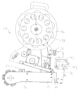
[0015] Fig. 3 is a right side view of the labeller.
[0016] Fig. 4 is perspective view of the labeller.
CA 02741531 2011-06-27
4
[0017] Fig. 5 is a front view of the labeller with the housing of the head
frame
removed.
[0018] Fig. 6 is a rear view of the labeller.
[0019] Fig. 7 is perspective view of the head.
[00201 Fig. 8 is a perspective view of the head with the cover removed.
[0021] Fig. 9 is a front view of the labeller showing the label web path.
100221 Fig. 10 is a front view of the labeller according to one embodiment of
the invention wherein a print system is engaged.
[0023] Fig. 11 is a left side view of the labeller with a print system
engaged.
[0024] Fig. 12 is a right side view of the labeller with the print system
engaged.
[0025] Fig. 13 is a perspective view of the labella with a print system
engaged.
[0026] Fig. 14 is a front view of the labeller with a print system engaged and
with the head partially removed from the cassette.
100271 Fig. 15 is a front view of the head with the print system attached,
[0028] Fig. 161s a close up view of the rewind mechanism in a first positice
taken approximately from the portion "A" circled in Fig. 1. For purposes of
illustration,
hidden objects are shown in dotted lines.
[0029] Fig. 17 is a close up view of the rewind mechanism in a second
position take approximately from the portion -A" circled in Fig, I. For
putposes of
illustration, hidden objects are shown in dotted lines.
= [0030] Fig. 18 is a front view of the flower petal gears.
[0031] Fig. 19 is a rear view of the flower petal gears.
CA 02741531 2011-06-27
DETAILED DESCIZIPTION QF THE cRIENT_EMBODINIENTS
I. Overview
[0032] A labeller according to one embodiment of the present invention is
shown in Fig. 1 and generally designated 10. The labeller IQ includes a frame
12 that is
generally a two-piece assembly including a cassette frame member 11 and a head
frame
member 13. In one embodiment, the head frame 13 pivots about .a portion of the
cassette
frame 11 for easy separation of the frame portions. The labeller may
additionally include a
print mechanism for printing information on the individual labels carried on a
label web, and
a mechanism for rewinding the waste liner of the label web after the labels
have been
removed.
H. Structure
(0033) The frame 12 may be configured to contain or support a variety of the
labeller head and cassette components, such as the labeller_components
described in detail in
'RS. Patents 6,729,375; 7,153,378; 7,158,574; and 7,363,954. The labeller
components may
be directly or indirectly attached to the frame. The frame 12 can be formed in
any suitable
size and shape and formed from a wide variety of materials, such as molded
plastic or metal.
[0034] In one embodiment, the cassette frame member 11 and the head frame
member 13 may each support a plurality of labeller components, including a
label wheel 86,
a peel plate 28, a first tractor wheel (or "drive wheel") 36, a second tractor
wheel (or "drive
wheel") 48, one or more tamping bellows 30, and a waste liner rewind wheel 88.
The label
wheel 86 and rewind wheel 88 are mounted on a rotatable shaft 90 extending
from the frame
12 and is capable of supporting a conventional label web 51 in roll form. The
label web 51
includes a release liner carrying a plurality of individual labels. Although
the label wheel 88
and rewind wheel 86 are referred to as "wheels," it should be appreciated that
they may be
any such devices that are capable of taking up the labels and the release
liner, for example, by
winding the labels or the release liner about the device.
CA 02741531 2011-06-27
6
[0035] As noted above, the two-piece frame 12 is generally formed from a
cassette frame member 11 and a head frame member 13. As discussed in more
detail below,
the cassette 11 and head 13 frame members may be separated to enable removal
and
replacement of either frame member. In one embodiment, the cassette frame 11
supports the
labeller components generally associated with the routing of the label web 51,
including the
label wheel 86, the rewind wheel 88, and rollers for routing the label web 51
from the label
wheel 86 to the peel plate 28 and for routing the release liner of the label
web 51 from the
peel plate 28 to the rewind wheel 88. The head frame 13 supports the labeller
components
generally associated with driving the label web 51 and tamping the labels,
including a drive
motor 44, a turret 26 supporting multiple bellows 30, and gears or other
mechanisms for
connecting the drive motor 44 to the turret 26 and to one or more drive wheels
36, 48.
[0036] As shown, the cassette frame member 11 includes a top edge 14
forming a handle 16, a bottom edge 18, a left side 20 and a right side 22. The
head frame
member 13 includes a top edge 19 engaging the bottom edge 18 of the cassette
frame II, a
left side 21, a right side 23 and a bottom edge 25. The corner formed between
the bottom
edge 25 and left side 21 may include a rounded extension to support a turret
26 and bellows
30 as discussed below. A housing or cover 33 can be mounted to the front face
of the head
frame member 13 to at least partially enclose the components of the bead 13.
The frame 12
may also incorporate all required controls to hecome a "stand-alone" tamping
bellows
labeller, as also discussed below. The frame 12 may also incorporate other
designs or parts
that torm a tamping bellows labeller.
[0037) Fig. 9 is a front view of the labeller 10 showing one embodiment of a
path for the label web 51 with arrows to indicate how the label web 51 is
wound around the
label components. Initially the cassette 11 is provided with a full label roll
wound around the
label wheel 86, which includes a pair of discs 60 and a hub 66. In one
embodiment, the label
wcb 51 is pulled from the label wheel 86 by the synchronized, selective
advancement of a
CA 02741531 2011-06-27
7
pair of tractor wheels 36, 48 due to the engagement of the label web 51 with
the tractor
wheels 36, 48 (where holes or other structure in the web 51 contact
protrusions or other
Atructure on the tractor wheels 36, 48). As the label web is pulled from the
label wheel 86, it
extends around a first roller 100, and then around the first tractor wheel 36.
The label web 51
is then routed around rollers 104 and 106, and then to the peel plate 28,
where the labels are
removed from the web 51 to be applied to products. The remaining waste liner
is then wound
around the second tractor wheel 48, a roller 108, and a roller 119 mounted on
a pivotable arm
111 discussed below. The waste liner is then talcen up on the waste liner roll
88, which
includes a pair of discs 62 and a hub 92, by advancement of the rewind drive
mechanism
discussed below. The label web 51 may be pre-loaded through the rollers and
tractor wheels
36, 48 when the cassette 11 is attached to the head 13, or it may be wound
after attachment to
the head 13. Although the illustrated embodiment includes two tractor wheels,
the labeller 10
may alternatively include only a single tractor wheel to drive the label web
51. For instance,
the tractor wheel 36 could be replaced with a roller.
[0038] The peel plate 28 is mounted to the cassette frame 13 adjacent to the
tamping bellows 30 and includes a terminal end 31, around which the label web
51 can be
drawn to separate the labels from the release liner of the label web. In one
embodiment, the
tractor wheels 36, 48 are capable of advancing the label web from the label
wheel 86 and
around the terminal end 31 of the peel plate 28. The tamping bellows 30
includes a tamping
face 32 that is movable between a retracted position and an extended tamping
position in
which the tamping face can engage the labels as they are separated from the
label web 51.
The rewind wheel 88 is rotatably mounted on the shaft 90 and is capable of
supporting the
release liner by winding the release liner about the rewind wheel 88. Tn one
embodiment, the
rewind wheel rotates about the shaft 90 independently of the label wheel 86.
[0039] The peel plate 28 can be formed in any suitable shape and size and can
include an upper surface 37 and a lower surface 35. In the illustrated
embodiment, the
CA 02741531 2011-06-27
8
terminal end 31 of the peel plate 28 is of a sufficient width such that the
individual labels are
peeled from the support wheel when they pass across the lower surface 35 and
turn about the
terminal 'end 31. In the illustrated embodiment, the peel plate 28
is positioned on the
cassette frame 11 adjacent the bellows 30, such that as the individual labels
are peeled from
the wheel, they can each be placed on the tamping face 32 of a bellows 30. In
one
embodiment, the peel plate 28 may move in and out or up and down or sideways
to release
labels from the liner to be picked up by the bellows.
(0040) Each bellows 30 is adapted to extend to tamp a label from the tamping
face 32 of the bellows onto an object, such as an item of produce. The
exterior of each
bellows 30 can be formed from a flexible material, such as rubber or silicone.
In the
illustrated embodiment, the bellows 30 has a series of accordion-like folds,
such that the
bellows 30 is capable of extending Outwardly to place the labels on thc
products and then
retracting to the previous position. The tamping face 32 of each bellows 30 is
perforated
with holes 39. In one embodiment, the label is held on the tamping face 32 via
vacuum
pressure communicated through the vacuum holes 39. The label can be deposited
on the item
by switching off a conventional vacuum source (not shown) in communication
with the
vacuum holes 39 when the bellows 30 is in an extended position. The bellows 30
may be
extended into the extended position by a positive pressure source (not shown)
in
= =
communication with the bellows 30. In one embodiment, both the vacuum and
pressure
supplies can be provided by an electric and/or pneumatic valve (not shown),
which may be
mounted to the frame 12 or any other suitable means for providing a vacuum
source or a
positive pressure source can be used. In one embodiment, the flexible bellows
may be made
fmm a clear (i.e. transparent or translucent) material, such that the internal
components of the
bellows 30 are visible through the flexible bellows material. The internal
components, such
as a check valve (not shown) may be made from a colored material that is
visible through the
CA 02741531 2011-06-27
9
flexible bellows materiaL In this way, an operator can visibly inspect
whethe,r or not the
internal components are included in the bellows and positioned correctly.
[0041] Although many different bellows designs may be used, including
single bellows designs and stationary bellows designs, in the illustrated
embodiment,
multiple bellows 30 are mounted to a rotating turret 20. As shown, the
rotating turret 20 is
positioned on the head frame 13 such that the turret 26 is located below the
peel plate 28
when the cassette frame 11 and head frame 13 are connected to each other. As
shown in Fig.
5, the turret 26 is mounted to the head frame 13 on a rotatable axle 49. In
the illustrated
= embodiment, the axle 49 supports a gear 40, which is rotatably connected
to the head frame
13.
[0042] Referring now to Fig. 5, the gear 49 may be driven by a variety of
= means to rotate the turret 26. In the illustrated embodiment, the gear 40
engages an
intermediate gear 42 on the head frame 13 that is interconnected to a drive
motor 44 mounted
on the head frame 13 via a series of mitre gears 46 also mounted on the head
frame 13. The
motor 44 may be a DC electric motor, AC electric 'motor, stepper motor, servo
motor,
pneumatic or hydraulic motor, electric or pneumatic or hydraulic linear or
rotary cylinder.
The motor 44 may start and stop intermittently or operate continuously. In
another
embodiment, the gear 40 is driven by a belt that also drives other labeller
components. In yet
another embodiment, the gear 44) is driven by a dedicated belt drive, or
another type of drive.
[0043] The motor 44 may also be used to drive the label web Silo advance
;he label web 51 from the label wheel 86 to the peel plate 28 and to drive the
release liner of
the label web 51 from the peel plate 28 to the waste liner rewind wheel 88. In
one
embodiment, the motor 44 is operatively connected to the tractor wheels 36, 48
on the
cassette frame 11(0 drive the tractor wheels 36, 48, and thus the label web
51. More
particularly, as shown in Figs. 5 and 6, the head frame 13 may include a head
gear 56
connected to the drive motor 44 that rotates upon actuation of the motor 44.
The head gear
CA 02741531 2011-06-27
56 may be connected to the motor 44 via a gear 53 mounted on an axle 52 that
extends
through the head frame member 13 and is interconnected to the motor 44 via the
mitre gears
46. The head gear 56 engages a cassette gear 54 on the cassette frame 11 when
the frames 11
and 13 are connecte.d. The cassette gear 54 is mounted on an axle that
e,xteads through the
cassette frame member 11 and supports the second tractor wheel 48 on the
opposite side of
the cassette frame member 11. The first tracmr wheel 36 is linked to the
second tractor wheel
48 via a series of gears 38 that drive the tractor wheels 36, 48 at the same
rate, or at another
desired rate. In another embodiment, the label web 51 and the turret 26 may be
driven by
multiple drives that are synchronised to move and/or rotate the various
components in time
with each other and/or at different speeds and/or different intervals during
the label dispense
and application cycle. The labeller speed can be controlled by an external
sensor (photo-
optic, inductive, capacitive, ultrasonic, laser or mechanical switch) that may
detect the
product and/or support mechanisms, calculates the product speed and adjusts
the labeller
speed. The labeller cycle activation can be controlled by internal and/or
external software
and/or electrical/electronic and/or hardware signal to start and/or stop
intermittently or
continuously.
[0044] The label position on the bellows 30 may he determined by a
combination of one or more sensors to detect the position of the labels on the
label web 51
and/or the position of the waste liner of the label web 51 after the labels
have been removed.
For example, the label position on the bellows 30 may he determined by a label
sensor 34 on
the head frame 13. In another embodiment, the label position on the bellows 30
may also be
determined by a sensor (not shown) positioned on the cassette frame that
detects the position
of the waste liner drive roller pins. The sensors may be a combination of one
or more photo
optic, laser, inductive, capacitive, or other electrical/electronic sensors.
The label position on
the bellows 30 may otherwise be determined by a toothed belt or gears that
mechanically
synchronize the label and bellow positions.
CA 02741531 2011-06-27
11
[0045] As noted above, the cassette frame 11 and head frame 13 may be
separated and rejoined, enabling replacement a either component. In the
illustrated
embodiment, show in Figs. 7 and 14, the head 11 includes a first slot 57
between tabs that
extend generally perpendicular to the top edge 19 of the cassette 11, and a
second slot 59
between tabs that extend at an angle from the top edge 19 of the head near the
right side 23 of
the cassette 11. A pair of pins 61 extend outwardly from the front face of the
cassette frame
member 11. The pins 61 align with the slots 57 and 59. In the illustrated
embodiment, the
cassette 11 is attached to the head 13 by sliding the rear pin 61 into the
angled slot 59, and
then forcing the front pin 61 into the perpendicular slot 57. The cassette 11
is removed by
lifting the front of the cassette 11 until the front protrusion 61 clears the
front slot 57 and then
sliding the cassette forward to release the rear protrusion 61 from the angled
slot 59.
[0046] The cassette 11 and head 13 may be configured to property align the
turret 26 when the cassette 11 is attached to the head. In one embodiment, the
cassette 11
and head 13 include flower petal type discs 63, 65 (shown in Figs. 18 and 19)
attached to or
formed as part of the cassette gear 54 and head gear 56 respectively. The
flower petal discs
63,65 may be mounted on the axles of the head gear and cassette gear such that
they rotate
directly with the respective gears. The flower petal discs each include an
undulating outer
edge 67, with multiple recesses 69 and lobes 71. The number of reeesces 69 may
correspond
to the number of bellows 30 on the rotating turret 26.. In this embodiment,
when the cassette
Ills attached to the head 13, the flower petal discs 63, 65 necessarily must
rotate to interfit
with each other. This ensures alignment of the turret 26, and bellows 30, in
one of six
positions. The flower petals are shown with a smooth, curved transition
between the lobes 71
and recesses 69 to facilitate smooth engagement of the \two flower petal discs
63, 65;
however, the flower petal discs may have a wide variety of alternative shapes
that provide
alignment. In another embodiment, the head gear 56 and cassette gear 54 are
manually
aligned by the operator when the head 13 is attached to the cassette 13.
CA 02741531 2011-06-27
12
[0047] In one embodiment, shown in Figs. 10-15, the labeller IP includes a
printing mechanism 41 adapted to print a desired printed material on the
labels before they
are placed onto objects. The printing mechanism 41 can be mounted on the frame
12 at one
or more label positions prior to the peel plate dispensing edge 31 to print
real-time, variable,
or the same product information and/or identification. For instance, in the
illustrated
embodiment, the print mechanism 41 is mounted to the cassette frame 11 along
the label path
such that it is spaced from the peel plate 28, to enable printing on labels
that are a few labels
away from the peel plate. Alternatively, the print mechanism 41 may positioned
on the label
path adjacent to the peel plate 28, to enable printing on the label that will
next be picked up
by a tamping bellows 30. The print mechanism may be one of a variety of print
technologies.
including ink-jet, direct thermal, thermal transfer, laser, ultra-violet or
special light =aim
In one embodiment, the printing mechanism 41 may be moveable along the label
path in one
or more directions, for instance, to enable printing the printed information
on the label while
the label is not in motion.
[0048] In the embodiment illustrated, the label web 511s routcd from the label
wheel 86 around the first tractor wheel 36, which (as noted above) includes
protrusions to
pmperiy position the label web 51 on the tractor wheel 36. This prevents the
label web 51
from moving and/or stretching with respect to the rollers and the tractor
wheels, and controls
the position of the printed image (known as "print registration") on the label
web 51. An
electronic positioning device, such as a rotary encoder 43, may he attached to
the tractor
wheel 36 or the print mechanism to precisely control the angle of rotation of
the idler roller in
order to properly register a label for printing. As illustrated, the print
mechanism 41 and
encoder are mounted to the right edge 23 of the head frame 13. The print
mechanism 41 is
mounted such that it extends upwardly from the side of the head 13 to prevent
interference
with the components of the cassette 11 and head 13 during the attachment of
the cassette 11
to the head 13. The print mechanism 41 rotates into place when the bead frame
13 and
CA 02741531 2011-06-27
13
cassette frame 13 are connected, such that the printer 45 can receive the
label web 51. As
shown, the printer 45 is positioned adjacent the label web 51 path between the
first tractor
wheel 36 and the roller 104. Tn an alternative embodiment, the print mechanism
41 and
encoder 43 can be attached to a different portion of the head 13 or to the
cassette 11, or, in
another embodiment, a print mechanism may be mounted separate from the
cassette 11 and
head .13 on a support structure (not shown) in a position to move into contact
with the label
web. In another embodiment, the print mechanism 42 includes a print
verification device 47,
such as a camera scanner, positioned along the label web path after the
printer 45. The print
verification device 47 is capable of imaging the printed material on the
labels and verifying
whether the material meets certain parameters, such as darkness or position.
[0049] In one embodiment, the print mechanism 41 is electrically coupled to
thc system controller (not shown) and a user input interface (not shown). .me
controller May
be programmed to allow amser to input a desired print type and control the
print mechanism
41 to output labels with that print type. The print mechanism 41 and/or
controller may
incorporate softwarc or hardware speed and/or position sensing device to
signal and control
the printer to print the information while matching the label dispensing speed
to maintain
accurate print location on the labels. in one embodiment, an encoder 43 may he
electrically
connected to the controller to control the print mechanism and/or signal the
software to
improve the print registration and/or print image quality (i.e. contrast,
darkness, dpi
resolution). The print verification device 47 may he electrically coupled to
the controller to
signal the controller when the printed material falls outside a predetermined
parameter set.
[0050] In the illustrated embodiment, the label wheel 86 and rewind wheel 88
are formed as a multi-disc assembly that supports both the pre-loaded label
roll and waste
liner. The label web or roll can be supported on the label wheel 86 between
the discs 60 and
wound around the label wheel hub 66. The waste liner portion of the label web
51, which
remains on the labeller 10 after the labels have been removed and applied to
products, may
CA 02741531 2011-06-27
14
be wound onto the rewind wheel 88 around the hub 92 between the discs 624 The
label wheel
86 and waste liner rewind wheel 88 may be rotatably mounted on the same shaft
90, such that
they rotate independently about the shaft 90.
[0051] During operation of the labeller 10, the diameter of the label web on
the label wheel 86 decreases, and the diameter of the waste liner on the waste
liner rewind
wheel 88 increases as the rewind hub 92 accumulates waste liner. Thus, the
rotation speed of
the label wheel 86 must vary with respect to the rotation speed of the rewind
wheel to avoid
unwanted tension or unwanted slack on the label web 51. In one embodiment, the
present
invention includes a rewind mechanism, including a rewind drive motor 70, to
drive the
rewind wheel separate from the label wheel 86. In one embodiment, the rewind
drive motor
70 is mounted to the head 13 for driving the rewind wheel 88 in order to lake
up the waste
label liner after a label or series of labels has been applied. As shown in
Figs. 5, 7, 8, 16 and
17, the rewind drive motor 70 is connected to the rewind drive wheel 86 by a
belt 80
extending around a pulley attached to mitre gear 74 and also around a pulley
(not shown) on
the rewind wheel 88. The mitre gear 74 is connected to the drive 70, however,
other linking
mechanisms may be used. In the illustrated embodiment, the rewind drive motor
70 is
activated by a motion sensor 72 at the top edge 19 of the head 13, such that
the rewind drive
motor 70 operates to turn the rewind wheel 88 when the motion sensor 72 is
triggered.
(0052) The motion sensor can be triggered by a trigger arm 75 that is mounted
to the cgsgette frame 11. Referring to Figs. 16 and 17, the trigger arm is
connected to the
cassette frame by a pin 84, such that the arm 75 can rotate about the pin 84.
As shown, the
arm includes a first portion 77 that extends upwardly from the pin 84 and a
Second portion 85
that extends downwardly from the pin 84 toward the motion sensor 72 on the
head 13. The
second portion 85 of the arm and the motion sensor 72 are positioned relative
to each other
such that the motion sensor 72 is actuated when the second portion 85 of the
arm moves to
the left (away from the right edge 22 of the cassette frame 11). The second
portion 85 is
CA 02741531 2011-06-27
biased to the right (toward the right edge of the cassette frame 11) by a
spring 87. A
pivotable arm Ill is positioned on the cassette frame 11 proximate to the
first portion 77 of
the trigger arm 75. The pivotable arm 75 includes a first end 112 mtatahly
mounted to the
cassette frame 11 and a second end 113 that supports the roller 110. The
pivotable arm 75
may be biased toward the right edge 22 of the cassette frame 11 by a spring
(not shown), but
in operation it is typically pulled to the left into a first position (Fig.
17) by the tension of the
release liner wrapped around the roller 110. When the pivotable arm 111 is
moved to the
right into a second position (Fig. 17), it engages the first portion 77 of the
trigger arm 75 and
pushes it to the right, thus pushing the second portion 85 of the trigger arm
to the left to
activate the rewind drive 70. If the tension in the release liner of the label
web 51 decreases
(Le. slack increases), the pivotable arm 111 drops to the second position,
engaging the trigger
arm 75 and moving the trigger arm 75 to activate the rewind drive 70 and
rotate the waste
liner rewind wheel 88.
[0053] In an alternative embodiment of the rewind mechanism, the belt 80
may have a relatively smooth outer surface, and in one embodiment is made from
a relatively
slippery material, such as urethane, such that the belt generally slips with
respect to one or
both of the pulleys. When the label wheel 86 is rotated by the advancement of
the label web
to apply a label, the increased friction between the belt 80 and the pulley on
the rewind wheel
causes the belt 80 to drive the rewind wheel 88 and thus take up any slack in
the Waste label
liner onto the rewind wheel hub. This rewind mechanism may he used in place of
the trigger
arm mechanism described above, or it may be used in combination with the
trigger arm
mechanism. for instance, as a safety device in the event that the trigger
mechanism fails. The
illustrated waste liner rewind mechanisms may he retrofitted onto existing
labellers by
replacing the gears or other rewind mechanism of the labeller with the trigger
arm or pulleys
and belt described above.
CA 02741531 2011-06-27
16
III. Operation
100541 In operation, the labeller 10 may begin by actuating the drive tuotor
44
to begin indexing the label web 51. The motor 44 may be electrically connected
to the
controller and a under input interface, such that the motor 44 is actuated by
the contreller
after a particular input by the user. When the motor is actuated, the tractor
wheel 36, 48
rotate at least an amount to index one label past the peel plate 28 and onto
the tamping face
32 of a bellows 30. In one embodiment, one 9r both of the tractor wheels 36,48
may include
a series of protrusions 50 around their circumference that interfit with holes
in the release
liner' to aid in pulling the label web 51 from the label wheel and around the
various idler
pulleys and other components to the peel plate 28. The rotation of the tractor
wheels 36, 48
pulls the label web 51 off the label wheel 86 and around the peel plate 28,
and pulls he waste
release liner onto the rewind wheel 88. In another embodiment, thc rotation of
the tractor
wheels 48 alone may be sufficient to advance the label web 51. In yet another
embodiment,
the tractor wheels 36, 48 may be connected to other labeller components, such
as the label
wheel 86 and rewind wheel 88 to aid in driving the label web 51.
[0055] As the label web 511s advanced around the peel plate 28, the labels are
separated from the release liner portion of the label web 51. The release
liner portion of the
web 51 is then pulled around the second tractor wheel 48. The release liner is
pulled around
the pulley 110 supported on the pivotable arm 111, and wound onto the rewind
wheel 88. As
noted above, as the release liner 51 extends around the pulley 110, the
tension in the web 51
pulls the pulley 110 and the arm 75 to the left. As the labeller 10 continues
to operate, and
slack develops in the release liner, the pulley 110 and arm 75 drop to the
right and into
engagement with the trigger arm 75, rotating the second portion 85 of the
trigger arm to the
left to activate the motion sensor 72 and thus drive the waste liner rewind
wheel 88 to take up
the slack in the waste liner. The movement of the pivotable are 111 and
actuation of the
CA 02741531 2011-06-27
17
rewind drive 70 will occur repeatedly, and "on-demand" to maintain tension in
the waste
liner.
[0056] In an embodiment including a print mechanism 41, as the label web 51
is indexed, the print mechanism 51 may print a desired printed material onto
each individual
label. The print registration is controlled by the first tractor wheel 315 and
the encoder 43,
which may interact with the controller and a user input interface to print the
correct printed
material at the correct location and with the correct contrast and resolution.
If included, the
print verification device may be controlled to verify that the printed image
is within
acceptable parameters, and to send a signal to the controller to signal the
user if the printed
image is outside such parameters.
(0057] The above description is that of the current embodiment of the
invention. Various alterations and changes can be madc without departing from
the spirit and
broader aspects of the invention as defined in the appended claims, which are
to be
interpreted in accordance with the principles of patent law including the
doctrine of
equivalents. Any reference to claim elements in the singular, for example,
using the articles
"a," "an," "the" or "said," is not to be construed as limiting the element to
the singular.