Note: Descriptions are shown in the official language in which they were submitted.
CA 02741742 2016-02-10
TITLE OF THE INVENTION
MODULAR, REDUCED-PRESSURE, WOUND-CLOSURE SYSTEMS AND
METHODS
10
BACKGROUND
The present invention relates generally to medical treatment systems and, more
particularly, to modular, reduced-pressure, wound-closure systems and methods.
Whether the etiology of a wound, or damaged area of tissue, is trauma,
surgery, or
another cause, proper care of the wound is important to the outcome. Unique
challenges exist
when the wound involves locations that require reentry, such as the peritoneal
cavity and more
generally the abdominal cavity. Many times when surgery or trauma involves the
abdominal
cavity, establishing a wound management system that facilitates reentry allows
for better and
easier care and helps to address such things as peritonitis, abdominal
compartment syndrome
(ACS), and infections that might inhibit final healing of the wound and the
internal organs. In
providing such care, it may be desirable to remove unwanted fluids from the
cavity, help
approximate the fascia and other tissues, or finally to help provide a closing
force on the
wound itself at the level of the epidermis. Unless otherwise indicated, as
used herein, "or"
does not require mutual exclusivity.
Currently, an abdominal opening on the epidermis may be closed using sutures,
staples, clips, and other mechanical devices to allow the skin to be held and
pulled. Such
1
CA 02741742 2016-02-10
devices often cause puncture wounds or other wounds. Moreover, if severe edema
occurs,
tremendous pressure may be placed on the closure device and the pressure may
cause harm.
For example, if the pressure rises due to edema, the sutures may tear out.
With respect to an overall system for allowing reentry into the abdominal
cavity, a
number of techniques have been developed. One approach is to place towels into
the cavity
and then use clips, such as hemostats, to close the skin over the towels.
While simple and fast,
the results are regarded as suboptimal. Another approach is the so-called
"Bogota bag." With
this approach, a bag is sutured into place to cover the open abdomen in order
to provide a
barrier. Still another approach, sometimes called a "vac pack," is to pack
towels in the wound
and then place a drain into the abdomen and cover the abdomen with a drape.
Finally, a
reduced pressure approach has been used. Such an approach is shown in U.S.
Patent
7,381,859 to Hunt et al. and assigned to KCI Licensing, Inc. of San Antonio,
Texas. U.S.
Patent 7,381,859.
SUMMARY
Problems with existing wound closure devices and reduced-pressure treatment
systems
are addressed by the systems, apparatus, and methods of the illustrative
embodiments
described herein. According to one illustrative embodiment, a modular, reduced-
pressure
wound-closure system includes a flexible strap operable to be formed into a
closed loop and a
plurality of modular closing members selectively coupled to the flexible
strap. Each of the
plurality of modular closing members includes an attachment member, a sealed
contracting
member, and a connection member. Each attachment member is for releasably
attaching to a
portion of the patient's epidermis proximate an edge of a surface wound and to
a portion of a
sealed contracting member. Each sealed contracting member is operable to
contract under
reduced pressure. Each connection member is coupled to a corresponding sealed
contracting
member and is operable to selectively couple to the flexible strap. Each
modular closing
member also includes a reduced-pressure interface fluidly coupled the sealed
contracting
member for delivering a reduced pressure to the sealed contracting member. The
modular,
reduced-pressure wound-closure system also includes a reduced-pressure source
fluidly
coupled to each reduced-pressure interface of each of the plurality of modular
closing
members.
2
CA 02741742 2011-04-27
WO 2010/051070 PCT/US2009/044245
According to another illustrative embodiment, a method of manufacturing a
modular,
reduced-pressure, wound-closure system includes the steps of forming a
flexible strap
operable to be shaped into a closed loop and forming a plurality of modular
closing members.
The step of forming a plurality of modular closing members may include, for
each of the
plurality of modular closing members, the steps of forming an attachment
member for
releasably attaching to a portion of the patient's epidermis proximate an edge
of the wound
and forming a sealed contracting member. The sealed contracting member is
operable to
contract when placed under reduced pressure. The step of forming a plurality
of modular
closing members further includes coupling a second end of the sealed
contracting member to
the attachment member and forming a connection member. The connection member
is
operable to selectively couple to the flexible strap. The step of forming a
plurality of modular
closing members further includes coupling the connection member to a first end
of the sealed
contracting member. The illustrative method may further include the steps of
fluidly coupling
the closing, reduced pressure source to the plurality of modular closing
members. The closing
reduced-pressure source is operable to deliver a reduced pressure to each of
the plurality of
modular closing members.
According to another illustrative embodiment, a method of providing a closing
force to
a surface wound on a patient includes the steps of providing a flexible strap
operable to be
shaped into a closed loop and providing a plurality of modular closing
members. The method
of providing a closing force further includes the steps of shaping the
flexible strap into a
closed loop proximate the surface wound and providing a reduced pressure
source. The
method of providing a closing force further includes the steps of fluidly
coupling the reduced-
pressure source to the plurality of modular closing members and delivering
reduced pressure
to each of the plurality of modular closing members. When reduced pressure is
delivered, the
modular closing members generate a closing force. In this illustrative
embodiment, each of
the plurality of modular closing members includes an attachment member for
releasably
attaching to a portion of the patient's epidermis proximate an edge of the
surface wound and a
sealed contracting member, which has a first end and a second end. The second
end of the
sealed contracting member is coupled to the attachment member. The sealed
contracting
member is operable to contract when placed under reduced pressure. Each of the
plurality of
modular closing members further includes a connection member coupled to the
first end of the
3
CA 02741742 2011-04-27
WO 2010/051070 PCT/US2009/044245
sealed contracting member and a reduced-pressure interface fluidly coupled the
sealed
contracting member for delivering reduced pressure to the sealed contracting
member.
Other objects, features, and advantages of the illustrative embodiments will
become
apparent with reference to the drawings and detailed description that follow.
BRIEF DESCRIPTION OF THE DRAWINGS
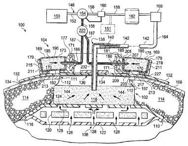
FIGURE 1 is a schematic cross-section, with a portion presented as a block
diagram, of
an illustrative embodiment of a modular, reduced-pressure, wound-closure and
treatment
system;
FIGURE 2 is a schematic, perspective view of an illustrative embodiment of a
portion
of a modular, reduced-pressure, wound-closure system;
FIGURE 3 is a schematic, cross-section of a portion of a modular closing
member of
the modular, reduced-pressure, wound-closure system of FIG. 2;
FIGURE 4 is a schematic, perspective view of the illustrative modular, reduced-
pressure, wound-closure system of FIGS. 2-3 shown deployed over a surface
wound of a
patient;
FIGURE 5 is a schematic, cross-sectional view of an illustrative embodiment of
a
portion of a modular closing member; and
FIGURE 6 is a schematic, cross-sectional view of an illustrative embodiment of
a
portion of a modular closing member.
4
CA 02741742 2016-02-10
DETAILED DESCRIPTION OF ILLUSTRATIVE EMBODIMENTS
In the following detailed description of the illustrative embodiments,
reference is made to the
accompanying drawings that form a part hereof. These embodiments are described
in sufficient detail
to enable those skilled in the art to practice the invention, and it is
understood that other embodiments
may be utilized and that logical structural, mechanical, electrical, and
chemical changes may be made.
To avoid detail not necessary to enable those skilled in the art to practice
the embodiments described
herein, the description may omit certain information known to those skilled in
the art. The scope of
the claims should not be limited by the embodiments set forth in the examples,
but should be given the
broadest interpretation consistent with the description as a whole.
Referring to FIGURE 1, an illustrative embodiment of a reduced-pressure, wound-
closure and
treatment system 100 is presented. The reduced-pressure, wound-closure and
treatment system 100
may include a reduced-pressure treatment subsystem 102 and a modular, reduced-
pressure, wound-
closure subsystem 104. The reduced-pressure treatment subsystem 102 may be
used for treating a
tissue site 106 with a reduced pressure. The tissue site 106 may be the bodily
tissue of any human,
animal, or other organism, including bone tissue, adipose tissue, muscle
tissue, dermal tissue, vascular
tissue, connective tissue, cartilage, tendons, ligaments, or any other tissue.
The tissue site 106 may be
within a body cavity, such as an abdominal cavity 110, and may include various
tissue layers including
a wound in epidermis 108. Treatment with the reduced-pressure treatment
subsystem 102 may include
removing fluids, such as ascites or exudates, delivering reduced pressure, or
providing a protective
barrier.
In the illustrative embodiment, the reduced-pressure, wound-closure and
treatment system
100 is presented in the context of the abdominal cavity 110 and a surface
wound 111, which has
wound edges 112. Other subdermal tissue 114 may also have been opened, such as
fat tissue, muscles,
fascia, etc. The abdominal cavity 110 is shown with abdominal contents 116,
which form a surface or
support.
The reduced-pressure treatment subsystem 102 of the reduced-pressure, wound-
closure and
treatment system 100 helps to deliver reduced pressure to the tissue site 106
and the abdominal cavity
110. The reduced-pressure treatment subsystem 102 includes a manifold 118
disposed within the
abdominal cavity 110 to distribute reduced pressure within the
5
CA 02741742 2011-04-27
WO 2010/051070 PCT/US2009/044245
abdominal cavity 110 and to receive fluids. The manifold 118 may include or be
associated
with a manifold member 120, or second manifold, in a non-adherent envelope
122. The non-
adherent envelope 122 has apertures 124 on a first side and apertures 126 on a
second, inward-
facing (tissue-facing) side. The apertures 124 and 126 facilitate flow of
fluids as suggested by
arrows 128. The apertures 124 and 126 may take any shape, such as rectangular
openings,
circular openings, polygons, slits (elongated slots), etc. The non-adherent
envelope 122 may
be formed from a flexible film, such as a polyurethane film, a drape material,
or any non-
adherent material.
Reduced pressure may be applied by reduced-pressure treatment subsystem 102 to
the
abdominal cavity 110 and the tissue site 106 to help promote removal of
exudates, ascites, or
other liquids, bacteria, fibrin, dead tissue, toxins, residual blood, etc.
Reduced pressure may
also be used in certain situations to stimulate growth of additional tissue.
In the case of a
wound at the tissue site 106, the growth of granulation tissue and removal of
exudates and
bacteria may help to promote healing of the wound. In the situation of a non-
wounded or non-
defective tissue, reduced pressure may be used to promote the growth of tissue
that may be
harvested and transplanted to another tissue site. In other situations, fluid
removal may be the
main reason for applying reduced pressure.
As used herein, "reduced pressure" generally refers to a pressure less than
the ambient
pressure at the tissue site 106. In most cases, the reduced pressure will be
less than
atmospheric pressure at which the patient is located. Alternatively, the
reduced pressure may
be less than the hydrostatic pressure of the tissue site 106. Unless otherwise
indicated, values
of pressure stated herein are gauge pressures.
The manifold 118 and manifold member 120 are disposed in the abdominal cavity
110
and may be disposed at or near the tissue site 106. Typically, the non-
adherent envelope 122,
which contains the manifold member 120, is disposed against the tissue site
106 and, in
particular, proximate the abdominal contents 116. The manifold 118 is disposed
adjacent the
non-adherent envelope 122. The manifold 118 and manifold member 120 may take
many
forms. The term "manifold" as used herein generally refers to a substance or
structure that is
provided to assist in applying reduced pressure to, delivering fluids to, or
removing fluids
from a tissue site, such as tissue site 106. The manifold 118 and manifold
member 120
typically include a plurality of flow channels or pathways that distribute
fluids provided to and
removed from the area proximate the manifold 118 and manifold member 120. In
one
6
CA 02741742 2011-04-27
WO 2010/051070 PCT/US2009/044245
embodiment, the manifold 118 and manifold member 120 include a plurality of
flow channels
or pathways that are interconnected to improve distribution of fluids. The
manifold 118 and
manifold member 120 may be formed from a biocompatible material that is
capable of being
placed in contact with tissue and that distributes reduced pressure. Examples
of manifolds
may include, without limitation, devices that have structural elements
arranged to form flow
channels, cellular foam, such as open-cell foam, porous tissue collections,
and liquids, gels
and foams that include or cure to include flow channels.
The manifold 118 and manifold member 120 may be porous and may be made from
foam, gauze, felted mat, or any other material suited to a particular
biological application. In
one embodiment, the manifold 118 and manifold member 120 are made from a
porous foam
that includes a plurality of interconnected cells or pores that act as flow
channels. The porous
foam may be a polyurethane, open-cell, reticulated foam, such as a GranuFoam
material
manufactured by Kinetic Concepts, Incorporated of San Antonio, Texas. Other
embodiments
may include "closed cells." In some situations, the manifold 118, the manifold
member 120,
and the non-adherent envelope 122 may be used to distribute fluids, such as
medications,
antibacterials, growth factors, and other solutions to the tissue site 106.
Other layers may be
included as part of the manifold 118 or manifold member 120, such as
absorptive material,
wicking material, hydrophobic material, and hydrophilic material.
A sealing member 132 may be placed over the surface wound 111 in epidermis 108
and, in particular, made to overlap the wound edges 112 to provide a pneumatic
seal. Thus,
the sealing member 132 provides a seal over the manifold 118 and the non-
adherent envelope
122. The sealing member 132 may be a cover that is used to secure the manifold
118 and non-
adherent envelope 122 at the tissue site 106. While the sealing member 132 may
be
impermeable or semi-permeable, the sealing member 132 is capable of
maintaining a reduced
pressure at the tissue site 106 after installation of the sealing member 132
over the manifold
118. The sealing member 132 may be a flexible over-drape or film formed from a
silicone
based compound, acrylic, hydrogel or hydrogel-forming material, or any other
biocompatible
material that includes the impermeability or permeability characteristics
desired for the
intended tissue site.
The sealing member 132 may further include an attachment device 136 to secure
the
sealing member 132 to a patient's epidermis 108. The attachment device 136 may
take many
forms; for example, a sealing tape might be used or an adhesive 134 may be
positioned along a
7
CA 02741742 2011-04-27
WO 2010/051070 PCT/US2009/044245
perimeter of the sealing member 132 or any portion of the sealing member 132
to provide a
pneumatic seal. The adhesive 134 might also be pre-applied and covered with a
releasable
member (not shown) that is removed at the time of application.
A first reduced-pressure interface 138, such as a port 140 or connector, may
be used to
deliver reduced pressure from a first reduced-pressure delivery conduit 142 to
the manifold
118. The first reduced-pressure interface 138 may also deliver any exudate,
ascites, or other
fluids from the manifold 118. The reduced pressure in the manifold 118 pulls
the fluid in the
direction shown by arrows 144 and to the first reduced-pressure delivery
conduit 142. The
first reduced-pressure interface 138 permits the passage of fluid from the
manifold 118 to the
first reduced-pressure delivery conduit 142. For example, fluids collected
from the tissue site
106 using the manifold member 120 and the manifold 118 may enter the first
reduced-pressure
delivery conduit 142 via the first reduced-pressure interface 138. In another
embodiment, the
reduced-pressure treatment subsystem 102 may exclude the first reduced-
pressure interface
138, and the first reduced-pressure delivery conduit 142 may be inserted
directly into the
sealing member 132 and the manifold 118. The first reduced-pressure delivery
conduit 142
may be a medical conduit, multi-lumen member, tubing, or any other means for
delivering a
reduced pressure.
A reduced-pressure subsystem 148 may be used to supply the reduced pressure
that is
delivered to the first reduced-pressure delivery conduit 142. The reduced-
pressure subsystem
148 may include a first reduced-pressure unit, or source, 150 that delivers
reduced pressure to
a conduit 152, which delivers the reduced pressure to a three-way valve 154.
One portion of
the reduced pressure may leave the three-way valve 154 through a second
reduced-pressure
delivery conduit 156. Another portion of the reduced pressure may leave the
three-way valve
154 through a reduced-pressure conduit 158. Located on the reduced-pressure
conduit 158
may be any number of devices, such as a reduced-pressure feedback unit 160,
which may, for
example, give feedback to the three-way valve 154 concerning the regulation of
the reduced
pressure within the reduced-pressure conduit 158. The reduced-pressure conduit
158 delivers
the reduced pressure to a canister 162, which is operable to hold any fluids
delivered to the
canister 162 from the tissue site 106. Reduced pressure leaving the canister
162 is delivered to
the first reduced-pressure delivery conduit 142. The first reduced-pressure
delivery conduit
142 may be referred to as delivering a treatment-reduced-pressure because the
reduced
pressure therein has been placed, by the reduced-pressure subsystem 148, at
the desired
8
CA 02741742 2011-04-27
WO 2010/051070 PCT/US2009/044245
pressure and conditions for use in reduced-pressure treatment at the tissue
site 106. The
reduced pressure delivered to the first reduced-pressure delivery conduit 142
is typically
selected to be in the range of -50 mm Hg to -500 mm Hg and more typically in
the range of -
100 mm Hg to -300 mm Hg at the tissue site 106.
A number of different devices, e.g., device 166, may be added to a medial
portion 164
of the first reduced-pressure delivery conduit 142. The device 166 might be a
pressure
feedback device, a volume detection system, a blood detection system, an
infection detection
system, a flow monitoring system, a temperature monitoring system, etc. Some
of these
devices may be formed integrally to other parts; for example, the canister 162
may include one
or more filters, e.g., a hydrophobic filter that prevents liquid from exiting.
There are many ways of developing or supplying the reduced pressure to be used
with
the reduced-pressure, wound-closure and treatment system 100. In the
illustrative
embodiment shown, the first reduced-pressure unit 150 is used for both
applications, i.e., for
wound closing and for reduced-pressure treatment. In an alternative
embodiment, it may be
desirable to use the first reduced-pressure unit 150 as the source for the
second reduced-
pressure delivery conduit 156 and have a second reduced-pressure unit 151
(shown in broken
lines) to deliver reduced pressure to the reduced-pressure conduit 158.
As an aspect of the reduced-pressure, wound-closure and treatment system 100,
it is
also desirable to help provide a closing force to the surface wound 111 and in
particular to
apply a closing force between the wound edges 112. As shown in FIGURE 1, the
modular,
reduced-pressure, wound-closure subsystem 104 may be used for this purpose.
The modular,
reduced-pressure, wound-closure subsystem 104 develops a closing force
represented by
arrows 170. The closing force is communicated to the epidermis 108 and urges
the wound
edges 112 towards each other. The modular, reduced-pressure, wound-closure
subsystem 104
may be a stand-alone system for closing any surface wound or used as part of a
larger system,
e.g., the reduced-pressure, wound-closure and treatment system 100.
The modular, reduced-pressure, wound-closure subsystem 104 includes a spacing
member, such as a flexible strap 171, which is shaped into a closed loop
inboard of the wound
edges 112 (see, e.g., FIG. 4), and a plurality of modular closing members 169
associated with
the flexible strap 171. Alternatively, the spacing member may be one or more
tie wires that
hold the modular closing members 169 in a spaced relationship or a flexible
adhesive film
placed on top of the modular closing members 169 that hold the modular closing
members 169
9
CA 02741742 2011-04-27
WO 2010/051070 PCT/US2009/044245
in a spaced relationship. Each modular closing member 169 has a sealed
contracting member
195, a connection member 181, and an attachment member 211. Before forming the
closed
loop, the plurality of modular closing members 169, e.g., a first modular
closing member 173
and a second modular closing member 175, are attached to the flexible strap
171. The
plurality of modular closing members 169 is analogous to the modular closing
members 308 in
FIGURE 2. The number of modular closing members 169 included on the flexible
strap 171 is
determined by the size of the loop needed to surround the surface wound 111.
Each modular closing member of the plurality of modular closing members 169
has a
first end 177, which is typically placed inboard of the surface wound 111, and
a second end
179, which is typically placed outboard of the surface wound 111. Each
connection member
181 is coupled to the first end 177 of the corresponding modular closing
member 169. In the
illustrative embodiment of FIGURE 1, each connection member 181 includes an
attachment
opening or loop 185 through which the flexible strap 171 may be placed. The
attachment
loops 185 allow each modular closing member 169 to be positioned in a desired
location along
the flexible strap 171.
A reduced-pressure interface 186 is coupled to each modular connection member
181.
A plurality of reduced-pressure conduits 187 is fluidly coupled to the reduced-
pressure
interface 186 to provide reduced pressure thereto. The reduced pressure
supplied through the
second reduced-pressure delivery conduit 156 is fluidly coupled to a
distributor 223 that is
fluidly coupled to the plurality of reduced-pressure conduits 187 that are
fluidly coupled to the
plurality of reduced-pressure interfaces 186 to deliver reduced pressure to
each modular
closing member 169. For each modular closing member 169, the reduced-pressure
interface
186 delivers reduced pressure to the sealed contracting member 195. Each
reduced-pressure
interface 186 may also function as a pin to hold the corresponding connection
member 181 in
place relative to the flexible strap 171.
Each modular closing member 169 of the modular, wound-closure subsystem 104
includes the sealed contracting member 195 that is used to develop a closing
force. The sealed
contracting member 195 may be formed from a contracting manifold material,
which may be
the same type of material as the manifold 118. Alternatively, it may be
desirable to use a
contracting manifold material that has fewer apertures or holes than the
material used for the
manifold 118. In addition, it may be desirable to have a material that will
contract less in the
vertical (for the orientation shown in FIG. 1) and more in the horizontal, or
lateral, plane (for
CA 02741742 2011-04-27
WO 2010/051070
PCT/US2009/044245
the orientation shown in FIG. 1). In an alternative embodiment, the sealed
contracting
member 195 may be formed with a pneumatic device to develop a closing force.
For example,
a chamber that collapses under reduced pressure may be used. The sealed
contracting member
195 has a first side 190 and a second, inward-facing side 192. The sealed
contracting member
195 is sealed to form a pneumatic seal about an interior space of the sealed
contracting
member 195.
Each connection member 181 of the plurality of modular closing members 169
includes a base 203 and a wall 209. The base 203 and wall 209 are formed
integrally or are
otherwise coupled by any technique, such as welding, bonding, adhesives,
cements, etc. Each
attachment member 211 has a base 213 and a wall 215. The base 213 and wall 215
of the
attachment member 211 are formed integrally or otherwise coupled by any
technique, such as
those previously mentioned. An adhesive 197 or other attachment device may be
used to hold
the sealed contracting member 195 to the base 203 of the corresponding
connection member
181. An adhesive 205 or other attachment device may be also be used to attach
a peripheral
edge 207 of the sealed contracting member 195 to a wall 209 of the
corresponding connection
member 181. An adhesive 217 or other attachment device may be used to hold the
sealed
contracting member 195 to the base 213 of the corresponding attachment member
211. An
adhesive 219 or other attachment device may also be used to hold the sealed
contracting
member 195 to the wall 215 of the corresponding attachment member 211. An
adhesive 227
or other attachment device may be used to releasably attach the base 213 to
the epidermis 108
(or sealing member if already deployed on epidermis).
In operation, the reduced-pressure, wound-closure and treatment system 100 may
be
used in a body cavity, e.g., abdominal cavity 110, by first applying a
manifold material on the
abdominal contents 116. For example, the manifold member 120 with the non-
adherent
envelope 122 may be placed on the abdominal contents 116 and the manifold 118
disposed
proximate the non-adherent envelope 122. The wound edges 112 of the surface
wound 111
may be brought together to the extent possible, and then the sealing member
132 placed onto
the epidermis 108 to provide a pneumatic seal over the surface wound 111.
The healthcare provider may measure or estimate the circumference of the
surface
wound 111 and then using a look-up table, determine the number of modular
closing members
169, e.g., first modular closing member 173, which need to be added to the
flexible strap 171.
The flexible strap 171 is also cut or otherwise sized to a proper length. The
plurality of
11
CA 02741742 2011-04-27
WO 2010/051070 PCT/US2009/044245
modular closing members 169, e.g., modular closing members 173 and 175,
desired are added
to the flexible strap 171. The flexible strap 171 is formed into a closed loop
that has a
circumference less than the circumference of the surface wound 111. The closed
loop is
substantially centered on the surface wound 111 and each of the attachment
members 211 are
secured to the patient's epidermis 108 (or to the sealing member 132). In this
regard, as used
herein, references to attaching to the patient's epidermis 108 should be
deemed to include
attachment to a sealing member 132 on the epidermis 108.
The first reduced-pressure interface 138, which may be the reduced-pressure
port 140,
may be applied such that an extended portion 202 reaches into the manifold
118. The first
reduced-pressure delivery conduit 142 may be coupled to the first reduced-
pressure interface
138 to provide a fluid coupling with the first reduced-pressure unit 150 (or
an optional second
reduced-pressure unit 151). The second reduced-pressure delivery conduit 156
may be fluidly
coupled to the distributor 223. The plurality of reduced-pressure conduits 187
are fluidly
coupled to the distributor 223 and to the plurality of reduced-pressure
interfaces 186.
The reduced-pressure, wound-closure and treatment system 100 is activated such
that
the first reduced-pressure unit 150 delivers reduced pressure through the
three-way valve 154,
which prepares the treatment-reduced-pressure that is delivered to the first
reduced-pressure
delivery conduit 142 and a closing-reduced-pressure that is delivered to the
second reduced-
pressure delivery conduit 156. The treatment-reduced-pressure delivered
through the first
reduced-pressure delivery conduit 142 is realized at the manifold 118, which
pulls fluids as
suggested by arrows 144 and 128 and distributes reduced pressure within the
abdominal cavity
110. The closing-reduced-pressure is delivered through the second reduced-
pressure delivery
conduit 156 to the distributor 223 and through the plurality of reduced-
pressure conduits 187
to the plurality of modular closing members 169. The closing-reduced-pressure
is received by
the plurality of modular closing members 169 and is delivered to the interior
of each of the
sealed contracting member 195, and causes each of the sealed contracting
members 195 to
contract and thereby to develop a closing force between the flexible strap 171
and the
attachment members 211. The net result is to provide a closing force urging
the wound edges
112 inward.
Referring now to FIGURES 2-4, an illustrative embodiment of a modular, reduced-
pressure, wound-closure system 300 is presented. The modular, reduced-
pressure, wound-
closure system 300 may be used as the modular, wound-closure subsystem 104 of
FIGURE 1.
12
CA 02741742 2011-04-27
WO 2010/051070 PCT/US2009/044245
The modular, reduced-pressure, wound-closure system 300 may include a flexible
strap 302
with a plurality of modular closing members 308. Each modular closing member
308 includes
an attachment member 320 and a connection member 314. Use of modular members
308
allows numerous sizes and shapes of surface wounds to be accommodated without
requiring a
large stock of different sizes and shapes of wound dressings or devices.
The flexible strap 302 is shown in a linear position in FIGURE 2 and shaped
into a
closed loop 304 in FIGURE 4. The flexible strap 302 is shaped into the closed
loop 304
around a surface wound 306, such as an opening on a patient's epidermis. The
plurality of
modular closing members 308 is selectively coupled to the flexible strap 302.
The number of
modular closing members 308 included on the flexible strap 302 is determined
by the size of
the closed loop 304 needed to surround the surface wound 306. Thus, to
surround the surface
wound 306 in FIGURE 4, eight modular closing members 308 have been included on
the
flexible strap 302. Referring again to FIGURE 2, each modular closing member
308 has a
first end 310 and a second end 312.
Each connection member 314 is coupled to the first end 310 of each modular
closing
member 308. In the illustrative embodiment of FIGURE 2, each connection member
314
includes an attachment loop or opening 316 through which the flexible strap
302 may be
placed. The attachment loops 316 allow each modular closing member 308 to be
positioned in
a desired location along the flexible strap 302. A portion of each attachment
loop 316 may
interface with a strap opening 318 to help hold the connection member 314 in
position on the
flexible strap 302. Alternatively or in addition, a reduced-pressure interface
326 may function
as a peg to hold the connection member 314 in place relative to the flexible
strap 302.
Referring now primarily to FIGURE 3, a connection member 314 is presented. The
reduced-pressure interface 326 is shown coupled to the connection member 314.
A reduced-
pressure conduit 327 is fluidly coupled to the reduced-pressure interface 326
to provide
reduced pressure to the reduced-pressure interface 326. The reduced-pressure
interface 326
delivers the reduced pressure to a sealed contracting member 328 and, as
previously
mentioned, the reduced-pressure interface 326 may function as a pin to hold
the connection
member 314 in place relative to the flexible strap 302.
The sealed contracting member 328 is made of the same or similar materials as
the
previously mentioned sealed contracting member 195 of FIGURE 1. The sealed
contracting
member 328 is sealed to form a pneumatic seal about an interior space of the
sealed
13
CA 02741742 2011-04-27
WO 2010/051070 PCT/US2009/044245
contracting member 328. An adhesive 329 or other attachment device (e.g.,
cement, weld,
hooks, etc.) may be used to hold the sealed contracting member 328 to a base
331. An
adhesive 335 or other attachment device (e.g., cement, weld, hooks, etc.) may
be also be used
to attach a peripheral edge 333 of the sealed contracting member 328 to a wall
323 of the
connection member 314.
Referring again primarily to FIGURE 2, an attachment member 320 may be coupled
to
each of the second ends 312 of the sealed contracting member 328. Each of the
attachment
members 320 may be formed with a base 322 and a wall 324. An adhesive (not
explicitly
shown) or other attachment device (e.g., cement, weld, hooks, etc.) may be
used to hold the
sealed contracting member 328 to the base 322. An adhesive (not explicitly
shown) or other
attachment device (e.g., cement, weld, hooks, etc.) may also be used to hold
the sealed
contracting member 328 to the wall 324.
Referring now primarily to FIGURE 5, an alternative reduced-pressure interface
427 is
presented as part of a connection member 416. Reduced pressure may be provided
to a sealed
contracting member 428 through the connection member 416. The connection
member 416
selectively attaches to a flexible strap 402. An adhesive 430 may be used to
hold the sealed
contracting member 428 to the connection member 416. The connection member 416
may
have a wall 424 and a base 422 that are formed integrally or otherwise coupled
by any
technique, e.g., welding (RF weld or ultrasonic), bonding, adhesives, cements,
etc. The
reduced-pressure interface 427 may be formed on the base 422 and configured to
enter a
manifold 480, or manifold pad. The reduced-pressure interface 427 is sized and
configured to
engage the manifold 480, which is in fluid communication with, or is fluidly
coupled to, a
reduced pressure source. The reduced pressure is delivered to the manifold 480
which
communicates the reduced pressure through the reduced-pressure interface 427
to the sealed
contracting member 428.
Referring again primarily to FIGURES 2-4, one illustrative method of operating
the
modular, reduced-pressure, wound-closure system 300 will be presented. In
operation, a
healthcare provider assesses the size of the surface wound 306 and determines
the number of
modular closing members 308 that are appropriate for the size of the surface
wound 306. A
look-up chart or table based on a measurement of the circumference of the
surface wound 306
may be used to suggest the appropriate number of the modular closing members
308. The
appropriate number of the modular closing members 308 is then selectively
coupled to the
14
CA 02741742 2011-04-27
WO 2010/051070 PCT/US2009/044245
flexible strap 302. The flexible strap 302 is then shaped into the closed loop
304, which is
preferably sized to be inboard of the peripheral edges of surface wound 306.
The flexible
strap 302 is secured to form the closed loop 304 using any number of means,
such as a ratchet,
snap, fastener, ratchet ties, flexible peg and slot members, etc. Then, each
of the plurality of
attachment members 320 is attached to the patient's epidermis proximate the
edge of the
surface wound 306. As before, the statement that the attachment members 320
are attached to
the epidermis may include that the attachment members 320 are attached to a
sealing member
being used for reduced-pressure treatment.
In applying each attachment member 320, the base 322 may have an adhesive (see
adhesive 227 in FIG. 1) or other attachment device applied on a second, inward-
facing surface
336. The adhesive may have a releasable backing on the adhesive that is
removed prior to use.
Thus, the healthcare provider would pull off the backing, exposing the
adhesive, and then
press the adhesive on the epidermis (or sealing member). Then, each reduced-
pressure
interface 326 associated with each of the plurality of connection members 314
is coupled to a
reduced-pressure source, such as by a reduced-pressure conduit 327 or a
distributor (not
shown). (Alternatively, the reduced-pressure interface 427 of FIGURE 5 may
have already
been introduced into the manifold 480 if used.) After activating the reduced-
pressure source,
reduced pressure is supplied to the reduced-pressure conduit 327 which
delivers the reduced
pressure through the reduced-pressure interface 326 to the sealed contracting
member 328.
The reduced pressure causes the sealed contracting member 328 to contract. As
the sealed
contracting member 328 contracts, the sealed contracting member 328 develops a
closing
force represented by arrows 340 in FIGURE 4. The closed loop 304 remains
substantially in
relative position, and thus each attachment member 320 pulls the epidermis
inward.
The closed loop 304 provides an open area in the middle of the closed loop 304
that
readily accommodates a reduced-pressure interface 342 if reduced-pressure
treatment is also
desired. The reduced-pressure interface 342 may be used to supply reduced
pressure to a
reduced-pressure treatment system (see, e.g., reduced-pressure treatment
subsystem 102 in
FIG. 1).
Referring now primarily to FIGURE 6, another alternative, illustrative
embodiment of
a reduced-pressure interface 526 is presented. The reduced-pressure interface
526 is formed as
part of an attachment member 520. The attachment member 520 includes a base
522 and a
wall 524 formed integrally or otherwise coupled. An adhesive 530 or other
attachment device
CA 02741742 2011-04-27
WO 2010/051070
PCT/US2009/044245
(e.g., bond, cements, weld, etc.) may hold, or secure, a portion of a
contracting member 528 to
the base 522. An adhesive 534 or other attachment device (e.g., bond, cements,
weld, etc.)
may hold a portion of the contracting member 528 to the wall 524. An adhesive
535 or other
attachment device (e.g., bond, cements, suture, etc.) on a inward-facing side
536 of the base
522 may be used to attach the base 522 to a patient's epidermis (or sealing
member). In this
illustrative embodiment, the reduced-pressure interface 526, which is fluidly
coupled to a
reduced-pressure conduit 527, extends through the wall 524 and delivers
reduced pressure to
the sealed contracting member 528.
Referring again to FIGURE 4, another embodiment will be presented. In this
alternative embodiment, a set number of the modular closing members 308 are
slideably
attached to the strap 302 and may be provided in a closure kit as such. When
applying the
wound-closure system 300, the healthcare provider appropriately spaces the set
number of
modular closing members 308¨usually equidistant from one another¨on a portion
of the
strap 302 to be used and forms the closed loop 304. Any extra portion of the
strap 302, i.e., a
portion not needed to form the closed loop 304, may be cut and removed.
According to another illustrative embodiment, a modular wound closure system
for
closing a wound on a patient's epidermis using reduced pressure includes a
plurality of closing
devices that contract when under the influence of reduced pressure. Each of
the closing
devices have a distal end and a proximal end. The system further includes a
flexible member
for maintaining the plurality of closing devices in a spaced relationship with
the proximal ends
inboard of an edge of the wound. The system also includes a plurality of
attachment
apparatuses for releaseably coupling the distal ends of the plurality of
closing devices to the
patient's epidermis outboard of the edge of the wound. The system further
includes a plurality
of reduced-pressure connectors for providing reduced pressure to the plurality
of closing
devices. The plurality of closing devices may be formed as a plurality of
sealed contracting
members. The plurality of closing devices may be detachably mated to the
flexible member.
The plurality of closing devices have a first volume (V1) at an ambient
pressure and have a
second volume (V2) at a reduced pressure and wherein V1 > V2. The plurality of
closing
devices may be slideably mated to the flexible member.
16
CA 02741742 2011-04-27
WO 2010/051070 PCT/US2009/044245
Although the present invention and its advantages have been disclosed in the
context of
certain illustrative, non-limiting embodiments, it should be understood that
various changes,
substitutions, permutations, and alterations can be made without departing
from the scope of
the invention as defined by the appended claims.
17