Note: Descriptions are shown in the official language in which they were submitted.
CA 02741747 2011-04-27
WO 2010/053725 PCT/US2009/061881
POROUS SURFACE LAYERS WITH INCREASED SURFACE ROUGHNESS AND
IMPLANTS INCORPORATING THE SAME
CROSS REFERENCE TO RELATED APPLICATIONS
[0001] This application claims the benefit of U.S. Provisional Application No.
61/109,395, filed 29 October 2008. The disclosure of this prior application is
incorporated
by reference in its entirety.
BACKGROUND OF THE INVENTION
Field of the Invention
[0002] The invention relates generally to surface layers with increased
roughness,
and more particularly to a method for increasing the roughness of a tissue-
engaging outer
surface of a porous structure without altering the pore size and porosity of
the structure, and
to medical implants incorporating said porous structure with increased surface
roughness.
Description of the Related Art
[0003] Especially in the medical fields, the surface of an implant, device, or
other
implement can significantly affect function. For example, attempts have been
made to
improve bone implant stability by increasing the roughness of the implant.
Other attempts
have been made to improve bone implant stability by providing pores in the
implant for bone
ingrowth.
[0004] One method of achieving bone ingrowth in implants that contact bone
(e.g., orthopedic implants) includes sintering metallic bead surfaces onto a
substrate. Other
methods of achieving bone ingrowth in implants includes using a reticulated
foam porous
coating fabricated from titanium that incorporates an electrical discharge
machined (EDM)
surface treatment, an EDM surface with axial grooves, an EDM surface with
cross-hatching,
or a photo-etched surface. Foam metal implants have been shown to achieve
greater bone
ingrowth than sintered bead implants. See, Urban, Robert M. et al.,
"Biomechanical and
Histological Response to a Novel Foam Metal Porous Coating with Comparison of
Two
Methods for Measuring Bone Ingrowth," Transactions of the 54th Annual Meeting
of the
Orthopaedic Research Society, p. 1854, March 2-5, 2008.
-1-
CA 02741747 2011-04-27
WO 2010/053725 PCT/US2009/061881
[0005] However, production of a porous metallic foam ingrowth structure (e.g.,
one created by applying fine metal powder particles to all surfaces of a
porous structure) can
require a secondary machining step to obtain the desired shape and dimensions
(e.g.,
tolerances) of the machined metal foam structure. Such machining can cause a
loss of
roughness on the machined surfaces (e.g., tissue-engaging outer surfaces). The
roughness
can be maintained or recovered using textured molds during sintering to
pressure-sinter
particles to a substrate without sacrificing texture for porous bead-coated
implants.
Alternatively, the roughness for a metallic foam can be maintained or
recovered using
electrical discharge machining ("EDM"), creating a cross-hatch pattern and,
upon
implantation, gaps between the grooves in the coating and bone. These
mechanisms have
thus far proved unsatisfactory in increasing the roughness of machined tissue-
engaging outer
surfaces of a porous metallic foam ingrowth structure while maintaining the
pore size and
porosity of the structure.
[0006] Therefore, there is a need for an improved method for providing a
porous
metallic foam structure with improved bone ingrowth characteristics that
avoids the
drawbacks discussed above.
SUMMARY OF THE INVENTION
[0007] Embodiments of the invention are directed to increasing the surface
roughness of a machined tissue-interfacing outer surface of a porous structure
without
altering the pore size or porosity of the porous structure.
[0008] In one embodiment a prosthetic implant comprises a machined reticulated
porous structure. A powder comprising asymmetric particles can be disposed on
a machined
tissue-interfacing outer surface of the porous structure. The asymmetric
particles can have a
size of between about 30% and about 70% of the pore size in the porous
structure so as to
increase the surface roughness of the machined tissue-interfacing outer
surface of the implant
while substantially inhibiting the occlusion of the open pores of the porous
structure and/or
without substantially modifying the porosity of the porous structure. In one
embodiment, the
porous structure can be a porous metal body. Similarly, the powder can in one
embodiment
be a metallic powder. In other embodiments, the porous structure and powder
can be of non-
metallic materials.
-2-
CA 02741747 2011-04-27
WO 2010/053725 PCT/US2009/061881
[0009] In another embodiment a prosthetic implant comprises a previously
machined reticulated porous structure to which one or more additional layers
of powder have
been applied to all surfaces of the previously machined reticulated porous
structure. A
powder comprising asymmetric particles can be disposed on a previously
machined tissue-
interfacing outer surface of the porous structure. The asymmetric particles
can have a size of
between about 30% and about 70% of the pore size in the porous structure so as
to increase
the surface roughness of the previously machined tissue-interfacing outer
surface of the
implant while substantially inhibiting the occlusion of the open pores of the
porous structure
and/or without substantially modifying the porosity of the porous structure
[0010] In accordance with another embodiment, a prosthetic implant is provided
comprising a machined reticulated porous construct applied to a solid surface.
A powder
comprising asymmetric powder particles can be adhered to a machined tissue-
interfacing
outer surface of the porous construct. The powder comprises a particle size
configured to
increase the surface roughness of the machined tissue-interfacing outer
surface of the porous
construct while substantially maintaining the open pores of the porous
construct.
[0011] In accordance with still another embodiment, a prosthetic implant is
provided comprising a previously machined reticulated porous construct to
which one or
more additional layers of powder have been applied to all surfaces and the
construct applied
to a solid surface. A powder comprising asymmetric powder particles can be
adhered to a
previously machined tissue-interfacing outer surface of the porous construct.
The powder of
asymmetric particles comprises a particle size configured to increase the
surface roughness of
the previously machined tissue-interfacing outer surface of the porous
construct while
substantially maintaining the open pores of the porous construct.
[0012] In accordance with yet another embodiment, a surface layer is provided
comprising a machined reticulated structure and a powder bonded to a machined
tissue-
interfacing outer surface of the reticulated structure. The powder comprises
asymmetric
titanium particles with a size of between about 75 microns and about 106
microns.
[0013] In accordance with another embodiment, a surface layer is provided
comprising a previously machined reticulated structure to which one or more
additional
layers of powder have been applied to all surfaces of the previously machined
reticulated
-3-
CA 02741747 2011-04-27
WO 2010/053725 PCT/US2009/061881
structure. A powder comprising asymmetric titanium particles with a particle
size of between
about 75 microns and about 106 microns can be bonded to a machined tissue-
interfacing
outer surface of the reticulated structure.
[0014] In accordance with still another embodiment, a method for increasing
the
surface roughness of a porous structure is provided. The method comprises
machining a
porous structure to a desired shape and bonding a powder, comprising
asymmetric powder
particles, to a machined tissue-interfacing outer surface of the machined
porous structure.
The powder particles are sized to increase the roughness of the machined
tissue-interfacing
outer surface of the machined porous structure, while preventing the occlusion
of the pores of
the porous structure and/or maintaining the porosity of the porous structure.
In one
embodiment, the porous structure is a porous metal foam and the powder
comprises a
metallic powder. In another embodiment the porous structure and powder are of
a non-
metallic material.
[0015] In accordance with yet another embodiment, a method for increasing the
surface roughness of a porous structure is provided. The method comprises
machining a
porous structure to a desired shape and applying one or more additional layers
of powder to
all surfaces of the porous structure. The method also comprises bonding a
powder,
comprising asymmetric powder particles, to a previously machined tissue-
interfacing outer
surface of the machined porous structure, said powder particles being sized to
increase the
roughness of the previously machined tissue-interfacing outer surface of the
machined porous
structure, while preventing the occlusion of the pores of the porous structure
and/or
maintaining the porosity of the porous structure.
BRIEF DESCRIPTION OF THE DRAWINGS
[0016] The invention will be described herein below by means of example
embodiments which are explained in detail with reference to the drawings, in
which:
[0017] Figure 1 depicts an enlarged image of a sintered metal foam pre-form of
the prior art. The sintered metal foam pre-form shown in Figure 1 is formed
using the steps
of: 1) providing a 60ppi polyurethane (PU) foam skeleton, 2) using a binder,
coating said
60ppi polyurethane (PU) foam skeleton on all of its surfaces with three layers
of fine
spherical metallic powder (e.g., spherical titanium powder) to create a "Pre-
form A", 3)
-4-
CA 02741747 2011-04-27
WO 2010/053725 PCT/US2009/061881
subsequently burning out the PU skeleton from "Pre-form A" as described in
reference to
Table 1 at 50x magnification to form a green metal foam, 4) subsequently
machining said
green metal foam to a desired shape using a wire electrical discharge
machining (WEDM)
process, and then 5) subsequently sintering the machined green metal foam to
form said prior
art sintered metal foam pre-form;
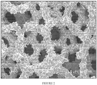
[0018] Figure 2 depicts an enlarged image of an improved sintered metal foam
pre-form according to one embodiment of the present invention. The improved
sintered
metal foam pre-form shown in Figure 2 may be formed using the steps of: 1)
providing a
60ppi polyurethane (PU) foam skeleton, 2) using a binder, coating said 60ppi
PU foam
skeleton on all of its surfaces with two layers of fine spherical metallic
powder (e.g.,
spherical Ti powder), 3) subsequently burning out the PU skeleton from the
resulting
construct to form a green metal foam, 4) subsequently machining said green
metal foam to a
desired shape using a wire electrical discharge (WEDM) process or the like to
form a
machined green metal foam, 5) subsequently applying an additional layer of
fine spherical
metallic powder (e.g., spherical Ti powder) to all surfaces of said machined
green metal foam
to form a "Pre-form B" as described in reference to Table 1 at 50x
magnification, and then 6)
subsequently sintering the Pre-form B to form said improved sintered metal
foam;
[0019] Figure 3 depicts an enlarged image of a "roughened metal foam"
according
to another embodiment of the present invention. The "roughened metal foam" may
be
formed using the steps of: 1) providing "Pre-form A" as discussed above, 2)
machining "Pre-
form A" to a desired shape using a wire electrical discharge machining (WEDM)
process or
the like, wherein the step of machining forms at least one machined tissue-
interfacing outer
surface, 3) applying at least one layer of asymmetric metallic powder
particles (e.g., titanium
or Ti dehydride particles) to said at least one machined tissue-interfacing
outer surface as
described in reference to Table 1 at 50x magnification, and 4) sintering the
resulting construct
to form said "roughened metal foam";
[0020] Figure 4 is an enlarged image of a cross-section of the Roughened Metal
Foam of Figure 3 showing a roughened porous metal foam structure with a
roughened tissue-
interfacing outer surface at 50x magnification (large image) and 85x
magnification (inset
image);
-5-
CA 02741747 2011-04-27
WO 2010/053725 PCT/US2009/061881
[0021] Figure 5 depicts topographical relief maps of the outer tissue-
interfacing
surfaces of "Pre-form A", "Pre-form B, and "Roughened Metal Foam",
respectively, as
described in reference to Table 2;
[0022] Figure 6 shows SEM images (25X) of machined and sintered metal foam
produced using (A) 60 ppi starting polyurethane foam and (B) 45 ppi starting
polyurethane
foam, with reference to Table 4.
[0023] Figure 7 depicts one embodiment of a method for preparing a porous foam
structure with a tissue-engaging outer surface having increased roughness.
[0024] Figure 8 depicts another embodiment of a method for preparing a porous
foam structure with a tissue-engaging outer surface having increased roughness
without
affecting the porosity and pore size of the porous structure.
[0025] Figure 9 depicts an embodiment of a femoral stem of a hip joint
prosthesis
with a roughened tissue-interfacing outer surface;
[0026] Figure 10 depicts an embodiment of an acetabular shell of a hip joint
prosthesis with a roughened tissue-interfacing outer surface;
[0027] Figure 11 depicts an embodiment of a shoulder prosthesis with a
roughened tissue-interfacing outer surface; and
[0028] Figure 12 depicts one embodiment of a knee joint prosthesis with a
tissue-
interfacing outer.
DETAILED DESCRIPTION OF THE PREFERRED EMBODIMENTS
[0029] The embodiments disclosed herein provide a porous structure with
increased surface roughness on a machined tissue-interfacing outer surface of
the structure
and methods of fabricating the same. The machined tissue-interfacing outer
surface generally
benefits from an increased roughness created by the application of a powder to
a porous
structure (e.g., porous metal body, porous foam material).
[0030] Generally, a tissue-interfacing outer surface with increased roughness
can
be applied to a porous metallic structure, a formed structure, the surface of
a pre-formed
structure, or some other object. In the case of medical articles, a bioinert
material such as
titanium, titanium alloys, tantalum, tantalum alloys, cobalt-chromium alloys,
zirconium,
zirconium alloys, and the like can be used for the porous structure. However,
other suitable
-6-
CA 02741747 2011-04-27
WO 2010/053725 PCT/US2009/061881
metallic and non-metallic materials can be used. Such non-metallic materials
can include
osteoconductive ceramics such as, for example, calcium phosphates (e.g., alpha
and beta
tricalcium phosphates, hydroxyapatite, etc). The material may be molded,
machined, or
processed in any known manner to a desired shape. Further, the material may be
solid, in
foam form (such as, for example, polyurethane foam), or a foam previously
applied to a solid
metal substrate composed e.g. of titanium, titanium alloys, tantalum, tantalum
alloys, cobalt-
chromium alloys, zirconium, zirconium alloys, or other suitable metallic and
non-metallic
materials.
[0031] Notably, as discussed above, machining (e.g. wire electrical discharge
machining ("WEDM")) can reduce the surface roughness initially provided to a
structure.
When the structure is for example a medical article to be implanted in bone,
the reduced
roughness can decrease any scratch-fit against the bone surface and reduce
implant stability.
As discussed above, roughness can be recovered using textured molds or using
WEDM to cut
grooves into the structure. Additionally, as known in the art, surface
roughness can be
recovered following machining with fine powder (e.g., particle size < 45 m)
layer(s) that can
be applied to all surfaces of a pre-form foam structure. However, this process
does not
achieve the desired level of surface roughness in the machined tissue-
interfacing outer
surface of the pre-form foam structure (see Table 1, below) to increase the
scratch-fit of the
pre-form structure against an interfacing surface (e.g., bone). Moreover, such
a process
disadvantageously reduces the porosity of the pre-form structure, which may
result in the
clogging or occlusion of the pores in the pre-form structure, thereby reducing
the ability of
bone to intergrow within the porous structure.
[0032] In some embodiments the powder can be chosen to optimally increase
roughness while maintaining pores open to the surface. In a preferred
embodiment a coarse
powder having a particle size of between about 75 and 106 m can be applied to
a machined
tissue-interfacing outer surface of the pre-form metal foam structure, as
further described
below, to increase the roughness of said tissue-interfacing outer surface
without altering the
porosity and pore size of the porous structure. However, said coarse particles
can have other
suitable sizes. In one embodiment, the porous structure can have a porosity of
between about
-7-
CA 02741747 2011-04-27
WO 2010/053725 PCT/US2009/061881
40% and about 85%. In another embodiment, the porous structure can have a
porosity of
between about 60% and about 80%.
[0033] In one embodiment, the porous structure can have an average pore size
of
between about 50 m and about 1000 m measured using a scanning electron
microscope
(SEM) or 2D metallographic techniques. In another embodiment, the porous
structure can
have an average pore size of between about 100 m and about 500 m. In still
another
embodiment, the porous structure can have an average pore size of about 200
m. However,
the porous structure can have other pore sizes. Additionally, the pore size of
the porous
structure (e.g., polyurethane foam) used to create the pre-form metal foam can
be varied to
affect the end pore size.
[0034] In a preferred embodiment, the size of the coarse powder particles can
be
between about 10% and 30% of the pore size of the porous structure. In another
embodiment, the size of the coarse powder particles can be between about 30%
and 70% of
the pore size of the porous structure. In still another embodiment, the size
of the coarse
powder particles can be between about 40% and about 60% of the pore size of
the porous
structure. However, the coarse powder particles can have other suitable sizes
relative to the
pore size of the porous structure so as to allow particles that are not bound
to the machined
tissue-interfacing outer surface of the porous structure to easily pass
through the pores of the
porous structure to inhibit (e.g., prevent) the clogging or occlusion of the
pores in the porous
structure.
[0035] The powder particles can be applied by dipping, spraying, sprinkling,
electrostatic methods, or any other appropriate methods. In one embodiment, a
binder can be
applied to the machined tissue-interfacing outer surface of the machined metal
foam
structure. The porous structure can then be dipped into a layer of coarse
powder particles to
coat the machined tissue-interfacing outer surface with said coarse powder
particles. In
another embodiment, the coarse powder particles can be sprinkled onto the
machined tissue-
interfacing outer surface of the porous structure after the binder has been
applied to said
surface. As discussed above, the coarse powder particles are preferably sized
to allow
particles that do not adhere to the tissue-interfacing outer surface to easily
pass through the
porous structure so as to inhibit (e.g., prevent) the clogging or occlusion of
the pores in the
-8-
CA 02741747 2011-04-27
WO 2010/053725 PCT/US2009/061881
porous structure. In still another embodiment, the coarse powder particles can
be sprayed
onto the machined tissue-interfacing outer surface of the porous structure
after the binder has
been applied to said surface.
[0036] Further, the powder can have other properties. In one embodiment the
coarse powder particles can be generally asymmetric, which can provide
additional roughness
for a given particle size. The fine and coarse powders can be of a variety of
materials, such
as titanium powder, commercially pure titanium powder ("cpTi"), titanium
hydride, and
titanium dehydride. However the powder can include other suitable metallic
materials, such
as titanium alloy, cobalt-chrome alloy, tantalum, zirconium, and zirconium
alloy, and suitable
non-metallic materials, such as calcium phosphates, hydroxyapatite, etc.
[0037] The fine and coarse powder can be applied by a variety of methods. For
example, a binder can first be applied to the porous structure, such as a
polyurethane foam.
Then, a layer of powder can be applied to the porous structure. The porous
structure can then
be sintered such that the powder bonds to the structure. In other embodiments,
the metal
foam structure to which the fine and coarse powder particles have been applied
can be
attached to some other structure (e.g., implant substrate), if desired.
[0038] More specifically, in one embodiment a polyurethane foam can be
provided, which can be cut to a desired size. The cut polyurethane foam can
then be
impregnated with a binder. A fine powder, such as cpTi, can then be applied to
all surfaces
of the polyurethane foam to form a starting metal foam structure. In one
embodiment, the
fine powder can be applied in one or two layers, or more if desired, with
binder applied to the
porous structure before application of each layer of powder. In another
embodiment, the fine
powder can be applied in one to four layers, or more if desired. Preferably,
the fine powder is
applied in sufficient layers to the polyurethane foam to form a porous
structure having the
desired characteristics (e.g., cell size, interconnecting pore size, average
pore diameter,
porosity, strength) for a particular application (e.g., medical applications
where the structure
provides for bone ingrowth) after the final sintering step. As used herein, a
pore can be an
interstitial pore in the exterior or interior of the foam or porous structure,
struts can be the
structural elements that define the pores, and the cell can be the volume
defined by struts with
the pores defined on an outer circumference of the cell. The starting metal
foam is then
-9-
CA 02741747 2011-04-27
WO 2010/053725 PCT/US2009/061881
heated at a temperature substantially above the decomposition temperature of
polyurethane to
burn out the polyurethane and form a green metal foam structure. The green
metal foam
structure can then be machined (e.g. WEDM) to desired shape to form a pre-form
metal foam
structure, which as described above, can result in a reduction of the
roughness of the
machined tissue-interfacing outer surface of the pre-form metal foam
structure. In one
embodiment, the number of layers of powder applied to the polyurethane foam
prior to
machining or wire EDM is just enough to increase foam strength to allow for
machining of
the green metal foam structure while inhibiting damage to the foam structure.
[0039] Following the machining of the green metal foam structure, additional
layers of fine powder can in one embodiment be applied to all surfaces of the
pre-form metal
foam structure to further strengthen and roughen the porous structure in order
to achieve a
desired structure strength and pore size (e.g., for a particular application)
upon final sintering.
Again, the powder here can be applied in one or more layers, as desired.
[0040] Once the machined pre-form metal foam structure has the desired
strength
and pore size (e.g., via the application of powder layers, as discussed
above), a binder can be
applied to a machined tissue-interfacing outer surface of the porous
structure. In a preferred
embodiment, one or more layers of coarse powder particles (e.g., asymmetric
particles) can
be applied to the binder-coated machined tissue-interfacing outer surface of
the pre-form
metal foam structure, as described above, to form a roughened pre-form. The
coarse powder
particles can be applied to the binder-coated machined tissue-interfacing
outer surface by
spraying, brushing, or sprinkling the coarse powder onto the binder-coated
outer surface, or
by dipping the binder-coated outer surface into a layer of coarse powder. The
coarse powder
can then be sintered onto the binder-coated outer surface to form a roughened
metal foam. In
another embodiment, the metal powder particles can be coated with binder and
applied to the
machined tissue-interfacing outer surface of the pre-form metal foam
structure. In one
embodiment, the roughened pre-form structure can be attached to a substrate
before the
coarse powder is sintered onto the binder-coated outer surface of the
roughened pre-form
structure.
[0041] In another embodiment, a porous titanium foam pre-form that has been
machined to size can be provided. A layer of binder can be applied to the
machined tissue-
-10-
CA 02741747 2011-04-27
WO 2010/053725 PCT/US2009/061881
interfacing outer surface of the pre-form structure, followed by a coarse
metal powder (such
as, for example, cpTi or titanium hydride), to form a roughened pre-form
structure. The
roughened pre-form structure can then be put through a final sintering,
bonding the coarse
powder to the pre-form to produce a roughened metal foam structure.
[0042] Samples of machined and sintered titanium foam pieces with and without
added powder layers have been tested. The texture of the machined tissue-
interfacing outer
surface of the samples was determined by measuring the coefficient of linear
friction of said
surface. The linear friction was measured against rigid polyurethane foam
(used to simulate
cancellous bone) using an orthopedic friction and wear testing machine
(OrthoPod), where a
normal load of approximately 44 N was applied to the sample part against the
polyurethane
foam and the foam rotated in an arc shaped motion at a displacement rate of
about 3.8
mm/sec. Further details of the linear friction test methodology used can be
found in "Friction
Evaluation of Orthopedic Implant Surfaces Using a Commercially Available
Testing
Machine," Gilmour et al., abstract #464 World Biomaterials Congress 2008, the
contents of
which are incorporated herein by reference in their entirety and should be
considered a part of
this specification, and which is attached as Appendix A.
[0043] Table 1 shows the friction results for three types of sintered Ti foam
surfaces: (1) a pre-form machined by WEDM from a green metal foam formed by
coating a
60ppi PU foam on all its surfaces with three layers of fine (<45 m) spherical
Ti powder, in
which all three layers were applied before machining ("Pre-form A"),
illustrated in Figure 1;
(2) a pre-form machined by WEDM from a green metal foam formed by coating a
60ppi PU
foam on all its surfaces with three layers of fine (<45 m) spherical Ti
powder, in which two
powder layers were applied before machining and one was applied after
machining ("Pre-
form B"), illustrated in Figure 2; and (3) Pre-form A with one layer of coarse
(75-106 m)
asymmetric Ti (Ti dehydride) powder applied after machining to the outer
tissue-interfacing
surfaces ("Roughened Metal Foam"), illustrated in Figures 3-4. As shown, the
surface with a
large asymmetric powder applied after machining had the highest coefficient of
linear friction
as compared to the other surfaces.
-11-
CA 02741747 2011-04-27
WO 2010/053725 PCT/US2009/061881
Table 1: Linear Friction Testing (n = 3 per group)
Test Sample Coefficient of Linear Friction
Pre-form A 0.90 0.09
Pre-form B 0.98 0.02
Roughened Metal Foam 1.09 0.10
[0043] Figure 1 shows sintered metal foam "Pre-form A" where the machined
tissue-interfacing outer surface of the porous metal foam structure has not
been roughened, as
discussed in embodiments herein. The pre-form metal foam structure has a cell
size diameter
of approximately 600 m with interconnecting pores of approximately 200 m in
diameter.
The overall average pore diameter (mean void intercept length (MVIL)) is
approximately
464.4 95.4 m. The average thickness of a strut (e.g., the support element
that defines the
cell) of the non-roughened metal foam is approximately 150 m. The average
gravimetric
porosity of the metal foam was 75.2 2.7%. Linear friction tests of the
machined tissue-
interfacing outer surface of "Pre-form A" resulted in a maximum linear
friction coefficient of
0.90 0.09.
[0044] Figure 2 shows sintered metal foam "Pre-form B" with a fine metal
powder applied to all surfaces of the machined porous metal foam structure
(i.e., the pre-form
metal foam structure). Pre-form B in FIG. 2 includes one layer of fine (<45
m) spherical
cpTi powder applied to the all surfaces of the pre-form structure after
machining of the green
metal foam structure. Linear friction tests of the machined tissue-interfacing
outer surface of
"Pre-form B" with the layer of fine spherical Ti powder applied after
machining resulted in a
maximum linear friction coefficient of 0.98 0.02.
[0045] Figures 3 and 4 illustrate a sintered "Roughened Metal Foam" structure
with a roughened machined tissue-interfacing outer surface achieved according
to a preferred
embodiment of the invention. As shown in FIGS. 3-4, a layer of metal powder
was applied
to the machined tissue-interfacing outer surface of a pre-form metal foam
structure such that
the overall pore size and porosity of the porous metal foam are not
substantially altered. The
metal powder applied to the pre-form metal foam illustrated in FIGS. 3 and 4
for increasing
the roughness of the machined tissue-interfacing outer surface of the pre-form
metal foam
was asymmetric titanium powder with particles approximately 75-106 m in size.
Because
-12-
CA 02741747 2011-04-27
WO 2010/053725 PCT/US2009/061881
the powder was applied only to the machined tissue-interfacing outer surface,
the average cell
size diameter and interconnecting pore size was not substantially different
from the pre-form
metal foam structure following application of the powder (e.g., MVIL of
Roughened Metal
Foam is approximately 448.9 34.5). Furthermore, the average gravimetric
porosity of the
roughened pre-form metal foam structure was substantially unchanged from that
of the pre-
form metal foam structure and is approximately 75.3 2.2%. Linear friction
tests of the
machined tissue-interfacing outer surface of the "Roughened Metal Foam" with
the layer of
coarse asymmetric Ti powder applied after machining resulted in a maximum
linear friction
coefficient of 1.09 0.10.
[0046] As depicted in Figure 5, white light interferometry was used to
determine
the difference in surface roughness of the metal foam struts on the machined
tissue-
interfacing outer surface of the sintered Ti Foam structures under the
following conditions:
"Pre-form A" (Wire EDM Surface) shown in Figure 1; "Pre-form B" (Wire EDM
surface
plus one layer of fine spherical Ti powder on all surfaces after machining of
the green state
metal foam structure), as shown in Figure 2; and "Roughened Metal Foam" (Pre-
form A plus
one layer of coarse (75-106 m) asymmetric Ti (Ti dehydride) powder applied to
the outer
tissue-interfacing surfaces after machining of the green state metal foam
structure), as shown
in Figures 3-4. The results are given in Table 2, with "Ra" representing the
average
roughness of all points from a plane fit to the test part surface, and "SRz"
representing the
average of the largest half of the radial peak-to-valley areal roughness
results. The
Roughened Metal Foam Ti Foam surface had the largest roughness values,
followed by the Ti
Foam "Pre-form B" with the fine spherical powder applied to all surfaces after
machining of
the green state metal foam structure and the machined "Pre-form A" Ti Foam.
These results
are reflective of the tactile feel of the surfaces, with the large asymmetric
powder coated Ti
Foam sample having the roughest feel.
Table 2. White Light Interferometry Results
Test Sample Ra(pm) SRz(pm)
Pre-form A 2.3 0.5 19.6
Pre-form B 6.2 0.7 40.6
Roughened Metal Foam 9.9 2.1 57.7
-13-
CA 02741747 2011-04-27
WO 2010/053725 PCT/US2009/061881
[0047] With reference to Figure 1, white light interferometry roughness
measurements of the machined tissue-interfacing outer surfaces of the "Pre-
form A" metal
foam structure resulted in an average roughness (Ra) of 2.3 0.50 m.
[0048] With reference to Figure 2, white light interferometry roughness
measurements of the machined tissue-interfacing outer surface of the "Pre-form
B" metal
foam structure with said additional layer of fine spherically-shaped metal
particles applied to
all surfaces of the pre-form structure resulted in an average roughness (Ra)
of about 6.2 m.
[0049] With reference to FIGS. 3-4, white light interferometry roughness
measurements of the roughened metal foam structure resulted in an increase in
average
roughness (Ra) of 9.9 2.1 m, significantly greater than the roughness of
either non-
roughened metal foam (Pre-form A or Pre-form B).
[0050] A summary of the properties describing the pre-form metal foam
structure
and roughened metal foam structure as shown in FIGS 1 and 3-4, respectively,
is given in
Table 3.
Table 3. Properties of Sintered Pre-form Metal Foam and Roughened Metal Foam
Pre-form A Roughened
Metal Foam Metal Foam
Cell Size Diameter (microns) -600 -600
Interconnecting Pore Size (microns) -200 -200
Average Pore Diameter (MVIL) (microns) 464.4 95.4 448.9 34.5
Gravimetric Porosity (%) 75.2 2.7 75.3 2.2
Strut Roughness (Ra) (microns) 2.3 0.50 9.9 2.1
Maximum Coefficient of Friction 0.90 0.09 1.09 0.10
[0051] Of the powders used to roughen the Ti Foam surface, the Titanium
Dehydride Powder -140 +200 Mesh (75-106 m), resulted in the bone interface
surface with
the highest friction, largest roughness value, and roughest texture as
assessed by tactile feel.
[0052] In other embodiments, the pre-form metal foam structure can have
variations in pore size and strut thickness. Additionally, the powder applied
to the machined
tissue-interfacing outer surface to increase its roughness can, in other
embodiments, have a
particle size greater than 106 m or smaller than 75 m. In another
embodiment, the shape
of the metal powder particles deposited on the machined tissue-interfacing
outer surface of
-14-
CA 02741747 2011-04-27
WO 2010/053725 PCT/US2009/061881
the pre-form metal foam structure can be shapes other than asymmetric.
Additionally, the
metal powder particles need not have a uniform shape.
[0053] Additional variations can involve the types of powder used and steps
taken
after the application of the powder. For example, different types and sizes of
powder can be
applied to different portions of an implant, for example where different
portions of the
implant will interface with different types of tissue. Further, different
types and sizes of
powder can be layered, so as to produce, for example, a fractal-like effect of
roughness at
varying sizes overlaid on one-another. Varying roughness sizes can allow
different
mechanisms of attachment with surrounding body tissue, such as simultaneously
allowing
tissue ingrowth at a macroscopic scale, while also allowing cellular adhesion
to an implant
surface at a smaller scale. To accomplish such varying roughness sizes, the
different powders
can be applied sequentially, creating for example a size gradient with a top
surface of small-
scale roughness and larger roughness directly beneath. Alternatively, in one
embodiment the
different powders can be applied simultaneously, creating a heterogeneous mix
of roughness
sizes.
[0054] In some embodiments, as the pore size increases, the strut thickness
can
also increase (see Table 4 and Figure 6). Both properties dictate the size
range of powder that
can be used to roughen the machined tissue-interfacing outer surface of the
pre-form metal
foam structure while maintaining an open surface porosity. The powder applied
to the tissue-
interfacing outer surface of the pre-form metal foam structure is preferably
sized to inhibit
(e.g., prevent) surface pore occlusion. In a preferred embodiment, powder
applied to the
tissue-interfacing outer surface of the machined foam metal structure has a
size of
approximately < 100% of the strut thickness and about < 50% of the pore size,
so as to
advantageously inhibit pore occlusion.
Table 4. Pore Size and Strut Thickness for Two Metal Foams of Different Pore
Densities. (Note: Starting Polyurethane Foam was coated with the same number
of metal powder layers to produce the 60 pores per inch (ppi) and 45 ppi Pre-
form
Metallic Foams.)
Starting Polyurethane Pore Size (MVIL) (microns) Strut Thickness (microns)
Foam Density
60 ppi 464.4 95.4 146 26
45 ppi 618.4 57.9 365 73
-15-
CA 02741747 2011-04-27
WO 2010/053725 PCT/US2009/061881
[0055] The shape and size of the surface roughening powder affects the
roughness
and frictional values of the roughened metal foam. Roughness and friction
properties of a
sintered Pre-form A metal foam structure (a WEDM surface) and a sintered Pre-
form B metal
foam structure (a WEDM surface with a layer of fine (<45) spherical powder
applied after
machining to all surfaces) are compared to Roughened Metal Foam with either
fine
asymmetric powder (<45 m) or coarse asymmetric powder (75 - 106 m), as shown
in
Table 5.
Table 5. Properties of Sintered Pre-form Metal Foams A and B (Not Roughened),
Fine Asymmetric Powder Roughened Metal Foam, and Coarse Asymmetric
Roughened Metal Foam
Fine Coarse
Pre-form A Pre-form B Asymmetric Asymmetric
Metal Foam Metal Foam Roughened Roughened
Metal Foam Metal Foam
Strut Roughness 2.3 0.50 6.2 0.70 6.4 0.98 9.9 2.1
(Ra) (microns)
Maximum
Coefficient of 0.90 0.09 0.98 0.02 0.97 0.01 1.09 0.10
Friction
[0056] Use of powders also provides advantages over other methods. For
example, the application of such powders can be simpler, easier, and cost
effective and does
not introduce grooves that would result in gaps between the bone and ingrowth
structure
upon implantation. Unlike overlying grids, the powder can be easily applied to
almost any
arbitrary geometry. Further, the powders can allow increases of roughness with
relative
precision (e.g., close tolerances) in regard to the end roughness of the
piece, as well as the
final geometry of the piece.
[0057] The layers described herein can be used with a number of medical
articles.
For example, the layer can be applied to a bulk metal foam augment to fill a
bone void, a
metallic foam-coated implant for a knee implant, hip implant, shoulder or
spinal application,
a tibial tray, acetabular shell, femoral stem, stem collar, other knee femoral
components, or
other medical implants or articles.
-16-
CA 02741747 2011-04-27
WO 2010/053725 PCT/US2009/061881
[0058] Figure 7 illustrates one embodiment of a method 100 for preparing a
roughened metal foam structure with a tissue-engaging machined outer surface
having
increased roughness without affecting the porosity and pore size of the porous
structure. The
method 100 includes cutting 110 a polyurethane foam having a desired pore size
to a desired
size and impregnating 120a the foam with a binder (e.g., a thermally
decomposing binder),
after which a first layer of fine powder (e.g., a bioinert metallic powder
such as titanium,
titanium alloy, tantalum, tantalum alloy, cobalt-chromium alloys, zirconium,
zirconium
alloys, etc.) is applied to the foam to form a starting metal foam. In the
illustrated
embodiment, the fine powder having a particle size of less than 45 pm is
applied 130a to all
surfaces of the porous polyurethane foam. The method 100 further includes
impregnating
120b the starting metal foam with binder and applying 130b a second layer of
fine powder,
after which the starting metal foam is further impregnated 120c with binder
and a third layer
of fine powder is applied 130c. However, more or fewer than three layers of
fine powder can
be applied so as to achieve the desired characteristics (e.g., pore size and
strength
requirements) of the starting metal foam, as discussed above. The method 100
additionally
includes burning out 140 the polyurethane to provide a green metal foam
structure. The
green metal foam structure can then be machined 150 to provide a pre-form
metal foam
structure. The steps 110-150 above for providing a pre-form metal foam
structure are known
in the art.
[0059] Advantageously, in the embodiments of the invention disclosed herein,
the
method 100 further includes applying 180 a binder to bone-interfacing machined
outer
surface of the pre-form metal foam structure and applying 190 a layer of
coarse asymmetric
powder with a particle size of between about 75 m and 106 m thereonto to
form a
roughened pre-form structure. Preferably, the layer of coarse asymmetric
powder is
deposited only on the bone-interfacing machined outer surface (e.g., the
coarse particles are
sized relative to the pores so that particles that are not deposited on the
bone-interfacing
machined outer surface pass through the pores of the metallic foam structure
without
clogging or occluding the pores of the structure). Though the method 100
discloses applying
one layer of coarse powder particles, one of ordinary skill in the art will
recognize that any
suitable number of layers of coarse metal powder particles can be applied. The
method 100
-17-
CA 02741747 2011-04-27
WO 2010/053725 PCT/US2009/061881
optionally includes attaching 195 the roughened pre-form structure to a
substrate. The layer
of coarse powder is then sintered 200 on the bone-interfacing outer surfaces
of the roughened
pre-form structure to form the roughened metal foam.
[0060] Figure 8 illustrates another embodiment of a method 100' for preparing
a
porous foam structure with a tissue-engaging outer surface having increased
roughness
without affecting the porosity and pore size of the porous structure. The
method 100' is
similar to the method 100 illustrated in Figure 7 so that similar steps are
identified with
identical numerical identifiers. The method 100' differs from the method 100
in that the
starting metal foam is twice impregnated 120a, 120b with a binder, and only
two layers of
fine powder are applied 130a, 130b to all surfaces of the starting metal
before machining of
the green state metal foam to provide a pre-form metal foam structure. As
discussed above,
the process of forming the pre-form metal foam structure is known in the art.
[0061] Advantageously, the method 100' includes impregnating 160 the pre-form
metal foam structure with binder and applying 170 a third layer of fine powder
to all surfaces
of the pre-form metal foam structure. However, one of ordinary skill in the
art will recognize
that any suitable number of layers of metal powder can be applied before
and/or after the
machining of the green state metal foam structure to achieve the desired
characteristics of the
metal foam structure, as discussed above. A layer of binder 180 and asymmetric
powder 190
is similarly applied and sintered 200 to the machined tissue-interfacing outer
surface to
increase the roughness of the pre-form metal foam so as to provide a roughened
metal foam
without altering the overall pore size and porosity of the structure so as to
inhibit (e.g.,
prevent) clogging of the pores in the roughened metal foam structure.
[0062] Embodiments of medical implants that can incorporate the roughened
tissue-interfacing outer surface on a porous structure, as described in the
embodiments above,
are depicted in Figures 9-12.
[0063] Figure 9 depicts an embodiment of a femoral stem 310 of a hip joint
prosthesis with a roughened tissue-interfacing porous outer surface, as
further described in
U.S. Patent No. 6,540,788, the contents of which are hereby incorporated by
reference and
should be considered a part of this specification. For example, the outer
surface of one or
more of the anterior/posterior sides 312, lateral side 314 and medial side 316
of the femoral
-18-
CA 02741747 2011-04-27
WO 2010/053725 PCT/US2009/061881
stem 310 can include a roughened porous structure having a roughened tissue-
interfacing
outer surface, as described above, to improve its fixation in a femoral
cavity. In one
embodiment, the substrate material of the femoral stem 310 can undergo a
surface treatment
(e.g., grit blasting), after which the roughened porous structure (e.g.,
roughened metal foam,
as described above) can be applied to the substrate.
[0064] Similarly, Figure 10 depicts an embodiment of an acetabular shell 320
for
a hip joint prosthesis, as further described in U.S. Pat. No. 6,537,321, the
contents of which
are hereby incorporated by reference and should be considered a part of this
specification.
The outer surface 322 of the acetabular shell 320 can include a roughened
porous structure
with a roughened tissue-interfacing outer surface, as discussed above, to
advantageously
increase the scratch fit of the acetabular shell 320 against the bone (e.g.,
the acetabulum) into
which its implanted, as well as allow for bone ingrowth into the porous
structure to provide
for greater stability of the implanted acetabular shell 320.
[0065] Figure 11 depicts an embodiment of a shoulder prosthesis including a
glenoid prosthesis 330, as further described in U.S. Publication No. 2006-
0111787, the
contents of which are hereby incorporated by reference and should be
considered a part of
this specification. The anchoring surfaces 332, 334 of the glenoid prosthesis
330 can include
a roughened porous structure with a roughened tissue-interfacing outer
surface, to facilitate
anchoring of the glenoid prosthesis in the scapula of a shoulder blade.
Similarly, bone
engaging surfaces 342, 344 of the humerus stem 340 of the shoulder prosthesis
can have a
roughened porous structure with a roughened tissue-interfacing outer surface,
as described in
the embodiments above, which can advantageously improve the scratch-fit of the
stem in
bone, as well as allow bone ingrowth into the porous structure to provide
improve stability of
the stem following implantation.
[0066] Figure 12 depicts an embodiment of a knee joint prosthesis 350
including
a femoral component 352 and a tibial component 360, as further described in
U.S. Patent No.
5,954,770, the contents of which are hereby incorporated by reference and
should be
considered a part of this specification. The bone engaging surfaces of the
femoral component
prosthesis 352, including the internal anterior 354 and posterior 356 condyle
surfaces, the
interior surface of the patellar shield 358, and the femoral anchoring stem
359 can include a
-19-
CA 02741747 2011-04-27
WO 2010/053725 PCT/US2009/061881
roughened porous structure with a roughened bone-interfacing outer surface
that can be
formed as disclosed in embodiments herein. Similarly, bone engaging surfaces
of the tibial
stem prosthesis 360, including exterior surfaces of the tibia plateau 362, 364
and tibia shaft
366 can include a roughened porous structure with a bone-interfacing outer
surface formed as
described in the embodiments above, to provide an increase scratch fit of the
tibial stem
prosthesis 360 in bone, as well as to allow for bone ingrowth into the porous
structure,
thereby providing improved stability of the tibial stem prosthesis 360
following implantation.
[0067] The embodiments of the invention described herein can also be
incorporated into a porous augment that can be implanted into a void in bone
or can be used
to fill a void, crack, cavity or other opening in bone, whether naturally
occurring or surgically
created.
[0068] Although the foregoing systems and methods have been described in terms
of certain preferred embodiments, other embodiments will be apparent to those
of ordinary
skill in the art from the disclosure herein. Additionally, other combinations,
omissions,
substitutions and modifications will be apparent to the skilled artisan in
view of the
disclosure herein. While certain embodiments of the inventions have been
described, these
embodiments have been presented by way of example only, and are not intended
to limit the
scope of the inventions. Indeed, the novel methods and systems described
herein may be
embodied in a variety of other forms without departing from the spirit
thereof. Accordingly,
other combinations, omissions, substitutions and modifications will be
apparent to the skilled
artisan in view of the disclosure herein.
-20-