Note: Descriptions are shown in the official language in which they were submitted.
CA 02741987 2011-04-28
WO 2010/049592 PCT/F12009/050874
1
METHOD AND APPARATUS FOR PRODUCING LIQUID BIOFUEL FROM SOLID
BIOMASS
FIELD OF THE INVENTION
The present invention relates to producing liquid biofuel from solid
biomass according to the preamble of claims 1, 17. More particularly the pre-
sent invention relates to a method and apparatus for producing liquid hydro
carbonaceous product from solid biomass by gasifying solid biomass in a gasi-
fier to produce raw synthesis gas, conditioning of the raw synthesis gas to pu-
rify the raw synthesis gas to obtain purified synthesis gas, the conditioning
comprising lowering the temperature of the raw synthesis gas in a cooler pro-
ducing saturated steam, subjecting the purified gas to a Fischer-Tropsch syn-
thesis in a Fischer-Tropsch reactor to produce liquid hydro carbonaceous
product and operating the superheating boiler substantially exclusively with
one or more by-products generated in the method for producing liquid hydro
carbonaceous product from solid biomass.
BACKGROUND OF THE INVENTION
It is know to produce liquid fuels starting from solid feedstock that
contains organic material. During the production the solid feedstock is
gasified
to convert it into raw synthesis gas. The formed raw synthesis gas is then
puri-
fied into a purified synthesis gas. The purified synthesis gas in further con-
verted into a liquid hydro carbonaceous product using Fischer-Tropsch -type
synthesis. The thus formed liquid hydro carbonaceous product may be then
upgraded to produce liquid bioguel. This kind of biomass to liquid processes
are generally know for example from publications US 2005/0250862 Al and
WO 2006/043112.
The temperature of the raw synthesis gas coming from the gasifica-
tion is generally at least about 700 C or more. During the purification of the
raw
synthesis gas the temperature of the synthesis gas has to be lowered to a
temperature needed for removing solid particles from the raw synthesis gas.
The lowering of the temperature of the raw synthesis gas is essential for
purifi-
cation steps, such as filtering step, water-gas-shift (WGS) step and scrubbing
step, arranged downstream of the cooling step. The raw synthesis gas is
cooled before conducting it into the filtering step, because if raw synthesis
gas
would be fed uncooled from the gasifier into a filter, the temperature of the
raw
CA 02741987 2011-04-28
WO 2010/049592 PCT/F12009/050874
2
synthesis gas could cause the particles removed from the raw synthesis gas to
sintrate or clog to the filter. Furthermore the WGS reactor and scrubber are
designed to operate at temperatures that are essential lower than about
700 C.
Accordingly, the temperature of the raw synthesis gas is lowered in
a cooler during the purification of the raw synthesis gas. During cooling the
temperature of the raw synthesis gas is lowered to between about 175 to 275
C, depending on the application. Cooler may comprise an evaporator or alter-
natively a feed water preheater and an evaporator. Thus during the cooling
steam may be generated in the cooler.
The problem relating to the cooling is that the raw synthesis gas to
be cooled consists mainly of hydrogen and carbon monoxide at reducing at-
mosphere. Because of the corrosive gas mixture of the raw synthesis gas the
heat surfaces of the cooler may face metal dusting, as a consequence of which
the cooler may produce only saturated steam, having temperature about 300
to 330 C. This kind of saturated steam cannot be utilized efficiently.
BRIEF DESCRIPTION OF THE INVENTION
An object of the present invention is to provide a method and an
apparatus so as to solve the above problems. The objects of the invention are
achieved by a method according characterizing portion of claim 1. The method
being characterized operating the superheating boiler substantially
exclusively
with one or more by-products generated in the method for producing liquid hy-
dro carbonaceous product from solid biomass. The objects of the invention are
further achieved by an apparatus according characterizing portion of claim 17.
The apparatus being characterized in that the superheating boiler is arranged
to be operated substantially exclusively with one or more by-products gener-
ated in the apparatus in the production of liquid hydro carbonaceous product
from solid biomass.
According to the present invention the saturated steam generated in
the cooling is further superheated in a superheating boiler for producing su-
perheated steam, having temperature about 500 to 550 C. Thus the saturated
steam generated in the cooler is converted in a form that may be utilized in a
steam turbine or in the process of producing liquid biofuel from solid biomass
itself.
CA 02741987 2011-04-28
WO 2010/049592 PCT/F12009/050874
3
In the present invention one or more by-products generated in pro-
ducing liquid hydro carbonaceous product from solid biomass is utilized as
fuel
in the superheating boiler. In one embodiment tail gas generated in the
Fischer-Tropsch synthesis is utlized as a fuel in the superheating boiler. In
an-
other embodiment of the present invention the raw synthesis gas is filtered in
a
filter to remove particles, such as ash and char, from the raw synthesis gas
and at least part of the particles filtered in the filter is utlized as a fuel
in the
superheating boiler. In yet embodiment of the present invention the raw syn-
thesis gas is purified by ultra purification for removing sulfur components,
C02,
H20, HCN, CH3CI, carbonyls, Cl and NOx sulfur from the raw synthesis gas
and at least part of the by-product gas generated is utilized or destroyed in
the
superheating boiler. In one embodiment of the present invention the liquid hy-
dro carbonaceous product obtained from Fischer-Tropsch synthesis is up-
graded into biofuel and at least part of the by-product fractions generated in
the upgrading is utilized as a fuel in the superheating boiler.
The advantage of the present invention is that superheating the
saturated steam generated in the cooling step changes the saturated steam
into a form that may be utilized further in the process of producing liquid
biofuel
from solid biomass or in a steam turbine. Thus, superheated steam produced
in the superheating may enhance the total efficiency of the process for produc-
ing liquid biofuel. A further advantage of the present invention is that by-
products originating from the process of producing liquid biofuel from solid
biomass may be utilised in the superheating as fuel for the superheating
boiler.
The superheating boiler may thus be operated substantially exclusively with
the by-products originating from the process of producing liquid biofuel from
the solid biomass. Thus the synthesis gas or any other product gas or liquid
generated in the process of producing liquid biofuel from the solid biomass is
not used for superheating and the overall yield of the process is not reduced.
BRIEF DESCRIPTION OF THE DRAWINGS
In the following the invention will be described in greater detail by
means of preferred embodiments with reference to the attached drawings, in
which
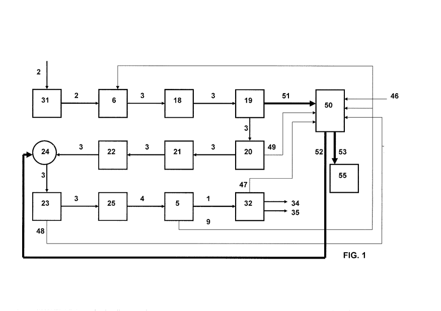
Figure 1 shows a schematic flow chart of one embodiment of the
present invention.
DETAILED DESCRIPTION OF THE INVENTION
CA 02741987 2011-04-28
WO 2010/049592 PCT/F12009/050874
4
Figure 1 is shows flow chart of one embodiment of a method and
apparatus for producing liquid biofuel from solid biomass. However, it should
be noted that the method and apparatus of the present invention comprises
gasification of solid biomass 2 in a gasifier 6 into raw synthesis gas 3,
condi-
tioning the raw synthesis gas by conditioning means 18, 19, 20, 21, 22, 24,
23,
25 into purified synthesis gas 4 and subjecting the purified gas 4 to a
Fischer-
Tropsch synthesis in a Fischer-Tropsch reactor 5 to produce liquid hydro car-
bonaceous product 1, but the composition of conditioning steps and condition-
ing means may vary from one embodiment to another.
As shown in figure 1, the solid biomass 2 is fed to a gasifier 6
through solid biomass pretreatment and supply means 31. In this application
the term solid biomass comprises substantially any kind of solid biomass that
is suitable to be gasified. The solid biomass is typically selected from
virgin
and waste materials of plant, animal and/or fish industry, such as municipal
waste, industrial waste or by-products, agricultural waste or by-products,
waste
or by-products of wood-processing industry, waste or by-products of food in-
dustry, marine plants and combinations thereof. The solid biomass may also
comprise vegetable oils, animal fats, fish oils. Natural waxes and fatty
acids, or
the like that may also be alternatively in liquid form. The biomass
pretreatment
and supply means 31 may comprise crusher and/or dryer for crushing the solid
biomass 2 and drying it to a moisture content less than 20%, preferably by
thermal drying. The biomass 2 pretreatment and supply means 31 may further
comprise a lock hopper for pressurising the solid biomass 2 at least to the
pressure prevailing in the gasifier 6.
From the solid biomass pretreatment and supply means 31 the bio-
mass 2 is fed to the gasifier 6. In the gasifier 6 the solid biomass 2 is
gasified
to produce raw synthesis gas 3 comprising carbon monoxide and hydrogen. In
this context the raw synthesis gas means synthesis gas that in addition to car-
bon monoxide and hydrogen can contain impurities such as carbon dioxide
(CO2), methane (CH4), water (H20), nitrogen (N2), hydrogen sulfide (H2S),
ammonia (NH3), hydrogen chloride (HCI), tar and small particles such as ash
and soot. The gasifying step comprises at least partial combustion of the
solid
biomass 2 in a gasifier 6 to produce the raw synthesis gas 3. The gasifier 6
may be fluidized bed gasifier, for example a circulating fluidized bed reactor
or
a bubbling fluidized bed reactor. Oxygen and steam having temperature of
about 200 C and in addition possible also recycled tail gas 9 from the Fischer-
CA 02741987 2011-04-28
WO 2010/049592 PCT/F12009/050874
Tropsch reactor 5 are used as fluidizing agents in the gasifier 6. The com-
pounds of solid biomass 2 will react with the steam endothermically generating
carbon monoxide and hydrogen and the compounds of the solid biomass 2 will
react with the oxygen exothermically generating carbon monoxide, carbon di-
5 oxide and additional steam. The result of this is the raw synthesis gas 3.
The
gasifier may operate for example at 10 bar and 850 C.
From the gasifier 6 the raw synthesis gas 3 is fed to the conditioning
or purification means to purify the raw synthesis gas obtained in the gasifica-
tion. In a preferred embodiment the conditioning of the raw synthesis gas 3
1o comprises a sequence of conditioning steps and apparatuses in which various
kind of conditioning of the raw synthesis gas is performed for purifying the
raw
synthesis gas 3 into a form suitable for a Fischer-Tropsch type synthesis.
This
means that for example the raw synthesis gas 3 is purified and the purified
synthesis gas has a molar ratio of hydrogen to carbon monoxide between 2,5
to 1 and 0,5 to 1, preferably between 2,1 to 1 and 1,8 to 1, and more prefera-
bly about 2 to 1.
From the gasifier 6 the raw synthesis gas 3 is fed to a reformer 18
for catalytic treatment for converting tar and methane present in the raw syn-
thesis gas 3 into carbon monoxide and hydrogen. Catalyst used in the reformer
18 may comprise for example nickel. Since tar and methane reforming are en-
dothermic chemical reactions, and raw synthesis gas leaving the gasifier 6 is
at
too low temperature, the raw synthesis gas will be heated up before feeding it
to the reformer 18, preferably by feeding oxygen into the raw synthesis gas.
To
prevent hotspots and ash melting, oxygen will be fired together with steam and
recirculated FT tail gas. Thus the temperature of the raw synthesis gas is for
example 900 C before the raw synthesis gas flows into the reformer.
Between the gasifier 6 and the reformer 18 there may also be one
or more particle separation steps for removing particles such as ash, char and
bed material from the raw synthesis gas 3. The particle separation steps are
performed preferably with one or more cyclones (not shown).
After the reformer 18 the raw synthesis gas 3 is fed to a subsequent
conditioning step in which it is fed to a cooler 19 for lowering the
temperature
of the raw synthesis gas 3. During cooling the temperature of the raw
synthesis
gas 3 is lowered to between about 175 to 275 C, preferably to about 250 C,
depending on the application. Cooler 19 may comprise an evaporator or alter-
natively a feed water preheater and an evaporator. Thus during the cooling
CA 02741987 2011-04-28
WO 2010/049592 PCT/F12009/050874
6
steam is generated in the cooler 19. The raw synthesis gas 3 to be cooled
consists mainly of hydrogen and carbon monoxide at reducing atmosphere.
Because of the corrosive gas mixture of the raw synthesis gas 3 the heat sur-
faces of the cooler 19 may face metal dusting, as a consequence of which the
temperature of the cooler 19 must be maintained in a range below the metal
dusting temperature. Because of this, the cooler 19 may produce only satu-
rated steam, having temperature for example about 300 to 330 C, at high pres-
sure, such as 115 bar.
The cooling of the raw synthesis gas is essential for the next condi-
tioning step, the filtering step following the cooling step. The raw synthesis
gas
3 has to be cooled before conducting it into the filtering step, because if
raw
synthesis gas is fed uncooled from the gasifier 6 into a filter 20, the
tempera-
ture of the raw synthesis gas 3 could cause the particles removed from the raw
synthesis gas 3 to sintrate or clog to the filter 20 used in the filtering
step. The
filter 20 comprises preferably a metallic or sinter candle filter. The filter
cake
will be removed from the filter elements by repeating nitrogen or CO pressure
shock. In the filter 20 solid particles, such as ash, soot, char and entrained
bed
materials are removed from the raw synthesis gas 3.
The conditioning of the raw synthesis gas 3 comprises preferably
also a step for adjusting the molar ratio of hydrogen and carbon monoxide by a
water- gas-shift reaction in a water-gas-shift (WGS) reactor 21 to between 2,5
to I and 0,5 to 1, preferably between 2,1 to 1 and 1,8 to 1, and more prefera-
bly about 2 to 1. The WGS reactor 21 is located downstream of the filter 20
and thus the filtered raw synthesis gas 3 is fed to the WGS reactor 21, as
shown in figure 1.
The raw synthesis gas 3 is preferably further conditioned in a
scrubber 22 to remove remaining solids, residual tar components and also
HCI, NH3 and other components from the raw synthesis gas 3 by scrubbing.
The scrubber 22 is may located downstream of the WGS reactor 2, preferably
such that raw synthesis gas 3 is fed from the WGS reactor 21 to the scrubber
22.
The conditioning of the raw synthesis gas 3 may also comprise ultra
purification means 23 for cleaning of the raw synthesis gas. The ultra
purifica-
tion means removes sulfur components, such as H2S, CO2 (carbon dioxide),
H2O (water), HCN (hydrogen cyanide), CH3CI (methyl chloride), carbonyls, CI
(chloride) and NOx (nitrogen oxide) from the raw synthesis gas 3. Preferably
CA 02741987 2011-04-28
WO 2010/049592 PCT/F12009/050874
7
the raw synthesis gas 3 is fed from the scrubber 22 to the ultra purification
means 23. The ultra purification may be performed with physical cleaning
process in which methanol or dimethyl ether is used a solvent at 30 to 40 bar
pressure and cryogenic temperatures -25 to -60 C. Alternatively the ultra
puri-
fication may be performed with chemical cleaning process in which the raw
synthesis gas is chemically washed, for example with amine.
Before ultra purification means 23 the pressure of the raw synthesis
gas 3 is raised in a compressor 24 to about 30 to 40 bar, such that the raw
synthesis gas 3 entering the ultra purification means is already at a suitable
pressure.
The conditioning may also comprise conditioning step comprising a
guard bed reactor 25 in which possible residual sulfur components are re-
moved from the raw synthesis gas 3. The guard bed reactor 25 comprises ZnO
catalyst and active carbon. Preferably the guard bed reactor 25 is located
downstream of the ultra purification means 23.
The conditioning of the raw synthesis gas 3 may comprise all the
above mentioned steps and apparatuses or it may comprise only some of the
steps and apparatuses described above. Furthermore, the conditioning means
and steps may also comprise some additional conditioning steps and appara-
tuses that are not described. The sequence of the conditioning steps and ap-
paratuses is preferably the above described, but it may also in some cases be
different.
From the conditioning means, and in this case from the guard bed
reactor 25, the purified synthesis gas 4, obtained from the raw synthesis gas
3
by the conditioning means, is fed to the Fischer-Tropsch reactor 5 for conduct-
ing the Fischer-Tropsch synthesis for the purified synthesis gas 4. In the
Fischer-Tropsch synthesis carbon and hydrogen monoxide are converted into
liquid hydrocarbons of various forms by catalyzed chemical reaction. The prin-
cipal purpose of this process is to produce a synthetic petroleum substitute
product, a liquid hydro carbonaceous product 1. The desired fuel component is
diesel fraction and as a by-product also Naphta is produced. Fischer-Tropsch
reactor 5 operates typically at a temperature of 200 to 220 C. Process in-
cludes an internal cooling and the produced heat can be utilized as low pres-
sure steam. The Fischer-Tropsch synthesis produces also so called tail gas 9
as a by-product.
The liquid hydro carbonaceous product 1 may further be fed from
CA 02741987 2011-04-28
WO 2010/049592 PCT/F12009/050874
8
the Fischer-Tropsch reactor 5 product upgrade section 32 where the he liquid
hydro carbonaceous products 1 will be first flashed to separate the light
hydro
carbons from the product stream. The flashed product stream will be hydro
cracked to maximize the diesel fraction. Hydro isomerisation will decrease the
cloud point of the diesel fraction enabling usage of the diesel product in
cold
climates. In the distillation process, the heavy fractions are separated and
cir-
culated back to hydro cracking and hydro isomerisation section. Distillation
also separates the final end products, diesel fractions 34 and naphtha
fractions
35 from each other. The product upgrade may also separate some by-product
fractions 47 from diesel and naphtha fractions 34, 35.
As described above, the temperature of the raw synthesis gas 3 or
the purified synthesis gas 4 has to be lowered in a cooler during the
condition-
ing of the synthesis gas because of the operating limits of the conditioning
means and Fischer-Tropsch reactor 5. The cooler 19 is preferably located to
the conditioning means and more preferably downstream of reformer 18 and
prior to filter 20. As mentioned earlier, the cooler 20 comprises an
evaporator
or alternatively a feed water preheater and an evaporator. Thus during the
cooling steam may be generated in the cooler 20. During cooling the tempera-
ture of the raw synthesis gas is lowered to between about 175 to 275 C, de-
pending on the application. Typically the temperature of the raw synthesis gas
3 is lowered to about 250 C. Cooler 19 produces high pressure saturated
steam 51 having preferably temperature about 300 to 330 C and pressure
about 100 to 130 bars. Typically the saturated steam 51 is at temperature
about 320 C and at pressure 115 bar.
According to the present invention the high pressure saturated
steam 51 is fed from the cooler 19 to a superheating boiler 50 for producing
superheated steam 52, 53. The superheating boiler 50 may be any known type
superheating boiler that is suitable for superheating steam. Superheating
boiler
is a combustion apparatus which is equipped with a superheater for superheat-
ing the saturated steam circulating in the superheater tubing. As fuel for the
combustion apparatus can be used different types of fuels. The superheated
steam 52, 53 leaving the superheating boiler 50 is typically at temperature be-
tween 500 to 550 C, preferably 510 C, and at pressure about 100 to 130 bars,
preferably at pressure 115 bar. This way the saturated steam from the cooler
19 may be converted into a form that may be utilized further in the method for
producing liquid hydro carbonaceous product 1 or for producing energy.
CA 02741987 2011-04-28
WO 2010/049592 PCT/F12009/050874
9
The superheated steam 53 may further be fed to a steam turbine 55
for producing electrical energy. In this application, superheating boiler 50
is
operatively connected to a steam turbine 55 for utilizing the superheated
steam
53 in the steam turbine 55. If the apparatus for producing the liquid carbona-
ceous product 1 is located in connection with an industrial plant or at site
of a
mill, such as forest industry plant, the superheated steam 53 may be used in a
steam turbine already existing. The forest industry plant may be a sawmill,
cel-
lulose mill, papermill comprising steam producing boiler(s), such as recovery
boiler, power boiler, waste heat boiler that produce steam for a turbine. In
that
case thermal power corresponding amount of thermal power of the super-
heated steam 53 utilized in the steam turbine 55 may be saved in the existing
boilers(s) of the forest industry plant. Thus the consumption of fuel may de-
crease.
Alternatively or additionally superheated steam 52 obtained from the
superheating boiler 50 may be utilized for pressurising the raw synthesis gas
3
or the purified synthesis gas 4 before supplying it into the Fischer-Tropsch
re-
actor 5. Thus the superheated steam 52 may also be fed from the superheat-
ing boiler 50 to the compressor 24, as is shown in figure 1. Thus the super-
heating boiler 50 is operatively connected to compressor 24 for utilizing the
superheated steam 52 to pressurise the raw synthesis gas 3 before supplying
it into the Fischer-Tropsch reactor 5.
In the present invention one or more by-products generated in the
method or process for producing liquid hydro carbonaceous product 1 from
solid biomass 2 is used as fuel in the superheating boiler 50. According to
the
present invention one or more by-products are used substantially exclusively
for operating the superheating boiler 50.
As described above, tail gas is generated in the Fischer-Tropsch
synthesis in the Fischer-Tropsch reactor 5. This tail gas 9 is very pure and
con-
tains combustible components. The main combustible components of the tail
gas 9 are carbon monoxide, hydrogen, and hydrocarbons C1-C5. Furthermore,
mass and energy calculations of the method for producing liquid hydro carbo-
naceous product 1 from solid biomass 2 indicate that the thermal power for
superheating the saturated steam 51 generated in cooler 19 and the thermal
power of the tail gas 9 correspond substantially to each other. Thus the tail
gas
9 can be used as fuel for the superheating boiler 50 and it may be fed to the
superheating boiler 50 with tail gas supply means. Some of the tail gas 9 may
CA 02741987 2011-04-28
WO 2010/049592 PCT/F12009/050874
also be recirculated to the gasifier 6. The tail gas supply means comprise
pipes
and possible valves or the like for conducting the tail gas 9 from the Fischer-
Tropsch reactor 5 to the superheating boiler 50.
Also at least part of the material filtered in the filter 20 may be util-
5 ized in the superheating boiler 50 as a fuel. The particles filtered from
the raw
synthesis gas 3 in the filter 20 comprise typically ash, soot and char. The
ash
comprises a lot of carbon, typically about 35 to 45 %. Therefore ash 49 may be
fed by particle supply means from the filter 20 to the superheating boiler 50
to
be used as fuel for superheating the saturated steam 51. The particle supply
10 means comprise pipes, conveyors or the like for conducting the ash 49 from
the filter 20 to the superheating boiler 50.
The ultra purification means 23 generates a H2S rich by-product gas
48 that contains also other sulfur components, CO2 (carbon dioxide), H2O (wa-
ter), HCN (hydrogen cyanide), CH3CI (methyl chloride), carbonyls, CI
(chloride)
and NOx (nitrogen oxide) as a result of the purification of the raw synthesis
gas. This by-product gas 48 may in some embodiments be fed by ultra purifi-
cation by-product supply means to the superheating boiler 50 to by used as
fuel in it. In the same time, or alternatively, the superheating boiler 50 is
also
capable to destroy the H2S rich gas 48 originated from the ultra purification
23.
This H2S rich gas 48 may not in all cases provide any additional fuel capacity
in the superheating boiler 50 but this provides an alternative process step to
destroy the odorous gas stream 48. If this H2S containing, odorous gas 48 is
burned in superheating boiler 50 the produced flue gases must be cleaned, for
example by scrubbing to remove sulphur oxide components. Also the burner in
the superheating boiler needs to be designed as low NOx burner to get the
NOx content of the flue gases below the NOx emission levels. The by-product
supply means may comprise pipes, valves or the like for conducting the by-
product gases 48 from the ultra purification 23 to the superheating boiler 50.
In the product upgrade section 32 by-product fractions 47 may be
generated in addition to diesel fractions 34 and naphtha fractions 35. These
fractions contain gaseous or liquid light weight hydrocarbons. Also at least
part
of the product upgrade by-product fractions 47 may be fed with product up-
grade by-product supply means to the superheating boiler 50 to be used as a
fuel for superheating the saturated steam 51. The product upgrade by-product
supply means may comprise pipes, valves or the like for conducting the by-
product fractions 47 from the ultra purification 23 to the superheating boiler
50.
CA 02741987 2011-04-28
WO 2010/049592 PCT/F12009/050874
11
The superheating boiler 50 is preferably also arranged to use light
fuel oil and/or natural gas as a support fuel 46 in the superheating boiler 50
for
example for adjusting or controlling the operation of the superheating boiler.
The support fuel 46 may also be utilized for start up. The tail gas 9 produced
in
the process provides substantially the same amount of fuel power as needed
for operating the superheating boiler 50 in normal operating conditions. When
necessary 15 % or less of the total fuel power of the superheating boiler 50
may be supplied as separate support fuel 46 for adjusting or controlling the
operation of the superheating boiler 50. In a preferred embodiment 10 % or
less, and more preferably 5 % or less of the total fuel power of the superheat-
ing boiler 50 may be supplied to the superheating boiler 50 as separate sup-
port fuel 46. According to the present invention, no synthesis gas or other
product gas or liquid is used to operate the superheating boiler 50. Therefore
using the superheating boiler 50 does not decrease the yield of the liquid bio-
fuel from the process.
Accordingly, the present invention provides that one or more by-
products 9, 47, 48, 49, generated in a process for producing liquid biofuel
from
solid biomass 2 may be used, as fuel in a superheating boiler 50 for superheat-
ing the saturated steam 51 originated from the cooling step. The saturated
steam originating from cooling the raw synthesis gas 3 in a process for produc-
ing liquid biofuel from solid biomass 2 may also be used for pressurising the
purified synthesis gas 4 in a compressor before supplying it into the Fischer-
Tropsch reactor 5. Therefore the energy efficiency of the method and appara-
tus for producing liquid hydro carbonaceous product 1 from biomass or the
energy efficiency of an industrial plant having integrated apparatus for
produc-
ing liquid hydro carbonaceous product 1 from biomass may be enhanced.
In one embodiment of the present invention feed water having tem-
perature of 103 C is supplied from the main boiler to the cooler 19. In the
cooler 19 the feed water is vaporized as it receives thermal energy from the
purified synthesis gas 4. The vaporized feed water attains temperature of 323
C forms saturated steam 51. The saturated steam 51 is supplied to the su-
perheating boiler 50 in which it is superheated to form superheated steam hav-
ing temperature of 510 C. In the superheating boiler, tail gas is used as
fuel.
Support fuel 46 may be used in the superheating boiler 50 for adjusting the
operation of the superheating boiler 50 to eliminate variations in the tail
gas
production.
CA 02741987 2011-04-28
WO 2010/049592 PCT/F12009/050874
12
It will be obvious to a person skilled in the art that, as the technology
advances, the inventive concept can be implemented in various ways. The in-
vention and its embodiments are not limited to the examples described above
but may vary within the scope of the claims.
CA 02741987 2011-04-28
WO 2010/049592 PCT/F12009/050874
13
LIST OF REFERENCE NUMERALS
1 Liquid hydro carbonaceous product
2 Solid biomass
3 Raw synthesis gas
4 Purified synthesis gas
5 Gasifier
9 Tail gas
18 Reformer
19 Cooler
20 Filter
21 Water Gas Shift (WGS) reactor
22 Scrubber
23 Ultra purification means
24 Compressor
25 Guard bed reactor
31 Solid biomass pre-treatment and supply means
32 Product upgrade means
34 Diesel fraction
35 Naphta fraction
46 Support fuel
47 Product upgrade by-product fractions
48 Ultra purification by-product gas
49 Filtered ash
50 Superheating boiler
51 Saturated steam
52 Superheated steam to steam to compressor
53 Superheated steam to steam turbine
55 Steam turbine