Note: Descriptions are shown in the official language in which they were submitted.
CA 02742159 2011-04-28
1
DESCRIPTION
BASE STATION APPARATUS, MOBILE TERMINAL APPARATUS,
MOBILE COMMUNICATION SYSTEM AND
INFORMATION RETRANSMISSION METHOD
Technical Field
[0001]
The present invention relates to a base station apparatus, mobile
terminal apparatus, mobile communication system and information
retransmission method, and more particularly, to a base station
apparatus, mobile terminal apparatus, mobile communication
system and information retransmission method using
next-generation mobile communication techniques.
Background Art
[0002]
In UMTS (Universal Mobile Telecommunications System) networks,
for the purpose of improving spectral efficiency and further
improving data rates, by adopting HSDPA (High Speed Downlink
Packet Access) and HSUPA (High Speed Uplink Packet Access), it
is performed exploiting maximum features of the system based on
W-CDMA (Wideband Code Division Multiple Access) . For the UMTS
network, for the purpose of further increasing high-speed data
rates, providing low delay and the like, Long Term Evolution (LTE)
CA 02742159 2011-04-28
2
has been studied (3GPP Release 8).
[0003]
In the 3G system, a fixed band of 5 MHz is substantially used,
and it is possible to achieve transmission rates of approximately
maximum 2 Mbps in downlink. Meanwhile, in the LTE scheme system,
using variable bands ranging from 1. 4 MHz to 20 MHz, it is possible
to achieve transmission rates of maximum 300 Mbps on downlink
and about 75 Mbps on uplink. Further, in the UMTS network, for
the purpose of further increasing the wide-band and high speed,
successor systems to LTE have been studied (for example, LTE
Advanced (LTE-A)). For example, in LTE-A, the widest system band
of 20 MHz in the LTE specification is scheduled to be extended
to about 100 MHz.
[0004]
Further, the LTE scheme system adopts multi-antenna radio
transmission techniques such as the MIMO (Multiple Input Multiple
Output) multiplexing method, and actualizes fast signal
transmission by transmitting different transmission signals
parallel from a plurality of transmitters using the same radio
resources (frequency band, time slot) to spatially multiplex.
In the LTE scheme system, it is possible to transmit different
transmission signals parallel from four transmission antennas
at the maximum to spatially multiplex. In LTE-A, the maximum
number (four) of transmission antennas in the LTE specification
is scheduled to be increased to eight.
CA 02742159 2011-04-28
3
[0005]
In addition, in the LTE scheme system, when a transmission error
occurs in an information bit, the receiver makes a retransmission
request, and in response to the retransmission request, the
transmitter performs retransmission control. In this case, the
number of blocks (hereinafter, referred to as "retransmission
blocks") each of which is a retransmission unit in performing
retransmission control is determined corresponding to the number
of transmission antennas irrespective of the system bandwidth
(for example, Non-patent Literatures 1 to 3) . Described herein
are the relationships in the LTE scheme between the system
bandwidth, the number of transmission antennas and the number
of retransmission blocks (the number of TBs), the retransmission
block size (BS). FIG. 13 is a table showing the relationships
in the LTE scheme system between the system bandwidth, the number
of transmission antennas and the number of retransmission blocks,
the retransmission block size. In addition, FIG. 13 shows 1.4
MHz, 5 MHz, 10 MHz and 20 MHz as the system bandwidth. Further,
the "layer" as shown in FIG. 13 corresponds to the number of
transmission antennas.
[0006]
As shown in FIG. 13, in the LTE scheme system, irrespective of
the system bandwidth, a single retransmission block is set in
the case of a single transmission antenna. Similarly, the number
of retransmission blocks is set at two in the case that the number
CA 02742159 2011-04-28
4
of transmission antennas is two, and also the number of
retransmission blocks is set at two in the case that the number
of transmission antennas is four. In other words, when the number
of transmission antennas is two or more, the number of
retransmission blocks is equally set at two. In addition, the
retransmission block size of the LTE specification is set at
150,000 bits at the maximum. FIG. 13 shows the case that the
retransmission block size is set at 150, 000 bits when the number
of transmission antennas is four, and that the retransmission
block size is set at 75, 000 bits when the number of transmission
antennas is two or less.
[0007]
Herein, FIG. 14 shows a conceptual diagram of the retransmission
block transmitted from the transmission antenna in the LTE scheme
system. As shown in FIG. 14, in the case of a single transmission
antenna, the retransmission block size is set at 75,000 bits,
and a transmission signal A of 75,000 bits is transmitted from
a transmission antennal. Further, in the case of two transmission
antennas, the retransmission block size is set at 75,000 bits,
and transmission signal A and transmission signal B each of 75, 000
bits are transmitted from the transmission antenna 1 and
transmission antenna 2, respectively. Furthermore, in the case
of four transmission antennas, the retransmission block size is
set at 150, 000 bits, transmission signalA and transmission signal
B each of 75, 000 bits are transmitted from the transmission antenna
CA 02742159 2011-04-28
1 and transmission antenna 2, and transmission signal C and
transmission signal D each of 75,000 bits are transmitted from
transmission antenna 3 and transmission antenna 4, respectively.
5 Citation List
Non-patent Literature
[0008]
[Non-patent Literature 1] 3GPP, TS 36.211 (V.8.4.0), "Evolved
Universal Terrestrial Radio Access (E-UTRA) ; Physical Channels
and Modulation (Release 8)", Sep. 2008
[Non-patent Literature 2] 3GPP, TS 36.212 (V.8.4.0), "Evolved
Universal Terrestrial Radio Access (E-UTRA); Multiplexing and
channel coding (Release 8)", Sep. 2008
[Non-patent Literature 3] 3GPP, TS 36.213 (V.8.4.0), "Evolved
Universal Terrestrial Radio Access (E-UTRA); Physical layer
procedures (Release 8)", Sep. 2008
Summary of the Invention
Technical Problem
[0009]
As described above, in LTE-A, it is scheduled that the maximum
system bandwidth is extended to about 100 MHz, and that the maximum
number of transmission antennas is increased to eight. In
applying the number of retransmission blocks in the LTE
specification as described above, even when the number of
CA 02742159 2011-04-28
6
transmission antennas is eight and the system bandwidth is 100
MHz, the number of retransmission blocks is set at two, and each
of the retransmission block sizes increases. In this case, even
when a single error occurs in information bits included in the
retransmission block, it is necessary to transmit the
retransmission block again, and retransmission efficiency is
considered deteriorating.
[0010]
The invention was made in view of such circumstances, and it is
an object of the invention to provide a base station apparatus,
mobile terminal apparatus, mobile communication system and
information retransmission method for suppressing deterioration
of retransmission efficiency and enabling a transmission signal
to be retransmitted efficiently even when the system bandwidth
is extended.
Solution to Problem
[0011]
A base station apparatus of the invention is characterized by
having retransmission block dividing section configured to divide
a transmission signal into retransmission blocks according to
a retransmission block table with which are registered the numbers
of the retransmission blocks, each of the transmission blocks
is a retransmission unit of a transmission signal, the numbers
of the retransmission blocks are required numbers corresponding
CA 02742159 2011-04-28
7
to the number of transmission antennas and the system bandwidth
in case that the maximum value of the size of the retransmission
block is fixed to a certain value, and retransmission section
configured to retransmit on downlink transmission signals
associated with the retransmission blocks divided by the
retransmission block dividing section.
[0012]
According to this configuration, a transmission signal is divided
into retransmission blocks according to a retransmission block
table with which are registered the numbers of the retransmission
blocks, each of the transmission blocks is a retransmission unit
ofa transmission signal, the numbers of the retransmission blocks
are required numbers corresponding to the number of transmission
antennas and the system bandwidth in case that the maximum value
of the size of the retransmission block is fixed to a certain
value, transmission signals associated with the retransmission
blocks are retransmitted on downlink, it is thus possible to
prevent a retransmission block exceeding the maximum value of
the retransmission block size to be retransmitted, and therefore,
also in the case that the system bandwidth is extended, it is
possible to suppress deterioration of retransmission efficiency
and to retransmit a transmission signal efficiently.
[0013]
A mobile terminal apparatus of the invention is characterized
by having reception section configured to receive transmission
CA 02742159 2011-04-28
8
signals divided into retransmission blocks according to a
retransmission block table with which are registered the numbers
of the retransmission blocks, each of the transmission blocks
is a retransmission unit of a transmission signal, the numbers
of the retransmission blocks are required numbers corresponding
to the number of transmission antennas and the system bandwidth
in case that the maximum value of the size of the retransmission
block is fixed to a certain value, and retransmission block
combining section configured to combine the retransmission blocks
to restore a transmission signal prior to division.
[0014]
According to this configuration, the mobile terminal apparatus
combines transmission signals divided into retransmission blocks
according to a retransmission block table with which are
registered the numbers of the retransmission blocks, each of the
transmission blocks is a retransmission unit of a transmission
signal, the numbers of the retransmission blocks are required
numbers corresponding to the number of transmission antennas and
the system bandwidth in case that the maximum value of the size
of the retransmission block is fixed to a certain value, and
restores a transmission signal prior to division, it is thus
possible to prevent a retransmission block exceeding the maximum
value of the retransmission block size to be retransmitted, and
therefore, also in the case that the system bandwidth is extended,
it is possible to suppress deterioration of retransmission
CA 02742159 2011-04-28
9
efficiency and to retransmit a transmission signal efficiently.
Technical Advantageous of the Invention
[0015]
According to the invention, a transmission signal prior to
division is restored by combining transmission signals divided
into retransmission blocks according to a retransmission block
table with which are registered the numbers of the retransmission
blocks, each of the transmission blocks is a retransmission unit
of a transmission signal, the numbers of the retransmission blocks
are required numbers corresponding to the number of transmission
antennas and the system bandwidth in case that the maximum value
of the size of the retransmission block is fixed to a certain
value, it is thus possible to prevent a retransmission block
exceeding the maximum value of the retransmission block size to
be retransmitted, and therefore, also in the case that the system
bandwidth is extended, it is possible to suppress deterioration
of retransmission efficiency and to retransmit a transmission
signal efficiently.
Brief Description of Drawings
[0016]
FIG. 1 is a conceptual diagram of a system band used in a mobile
communication system according to an Embodiment of the invention;
FIG. 2 is a diagram to explain a configuration of the mobile
CA 02742159 2011-04-28
communication system having a base station apparatus and mobile
terminal apparatuses (UEs) according to above-mentioned
Embodiment;
FIG. 3 is a functional block diagram of a transmission section
5 that is a principal part of the base station apparatus that the
mobile communication system has according to the above-mentioned
Embodiment;
FIG. 4 is a functional block diagram of a reception section that
is a principal part of the mobile terminal apparatus that the
10 mobile communication system has according to the above-mentioned
Embodiment;
FIG. 5 is a diagram showing an example of a retransmission block
table that the base station apparatus refers to in performing
retransmission control according to the above-mentioned
Embodiment;
FIG. 6 is a conceptual diagram of retransmission blocks
transmitted from the base station apparatus according to the
retransmission block table as shown in FIG. 5;
FIG. 7 is a schematic diagram to explain an example of information
bits and redundant bits rearranged in an interleave section of
the base station apparatus according to the above-mentioned
Embodiment;
FIG. 8 is a schematic diagram to explain details of interleaving
in a conventional mobile communication system;
FIG. 9 is a diagram to explain the scope of the diversity effect
CA 02742159 2011-04-28
11
obtained in interleaving in the conventional mobile communication
system;
FIG. 10 is a schematic diagram to explain another example of
information bits and redundant bits rearranged in the interleave
section of the base station apparatus according to the
above-mentioned Embodiment;
FIG. 11 is a diagram to explain an example of retransmission request
signals generated in a control signal generating section of the
mobile terminal apparatus according to the above-mentioned
Embodiment;
FIG. 12 is a sequence diagram to explain operation in the case
that the base station apparatus retransmits a transmission signal
to the mobile terminal apparatus according to the above-mentioned
Embodiment;
FIG. 13 is a table showing the relationships in an LTE scheme
system between the system bandwidth, the number of transmission
antennas and the number of retransmission blocks, the
retransmission block size; and
FIG. 14 is a conceptual diagram of retransmission blocks
transmitted from the base station apparatus according to the
retransmission block table as shown in FIG. 13.
Description of Embodiments
[0017]
An Embodiment of the invention will specifically be described
CA 02742159 2011-04-28
12
below with reference to accompanying drawings. In addition, the
following description is given using an LTE-A (LTE Advanced)
scheme system as an example of a successor system to LTE, but
the invention is not limited thereto.
[0018]
FIG. 1 is a conceptual diagram of a system band used in a mobile
communication system according to an Embodiment of the invention.
As shown in FIG. 1, the system band used in the mobile communication
system is divided using a base frequency block as a unit. The
entire transmission band of the base station apparatus
constituting the mobile communication system includes a plurality
(herein, five) of base frequency blocks. The bandwidth of the
base frequency block preferably ranges from about 15 to 20 MHz
to support the LTE-capable UE (User Equipment) . In the following
description, described is the case where the bandwidth of the
base frequency block is 20 MHz.
[0019]
A plurality of base frequency blocks is flexibly assigned to an
LTE-A-capable UE having the capability of transmission/reception
bandwidth wider than 20 MHz based on frequency diversity gain
and overhead of a control signal. For example, a single base
frequency block is assigned to an LTE-capable UE having the
capability of transmission/reception bandwidth of 20 MHz.
Meanwhile, two base frequency blocks are assigned to an
LTE-A-capable UE having the capability of transmission/reception
CA 02742159 2011-04-28
13
bandwidth of 40 MHz. Further, five base frequency blocks are
assigned to an LTE-A-capable UE having the capability of
transmission/reception bandwidth of 100 MHz. In addition, the
LTE-A-capable UE having the capability of transmission/reception
bandwidth wider than 20 MHz may be assigned base frequency blocks
less than the transmission/reception bandwidth thereof, for
example, a single base frequency block.
[0020]
In the mobile communication system according to the Embodiment,
under the environment that UEs with different
transmission/reception bandwidths thus coexist, in the case of
retransmitting a transmission signal to each of the UEs, the
deterioration of retransmission efficiency is suppressed, and
a transmission signal is retransmitted efficiently. More
specifically, a transmission signal is divided into
retransmission blocks in performing retransmission control,
according to a retransmission block table with which are
registered the numbers of the retransmission blocks, each of the
transmission blocks is a retransmission unit of a transmission
signal, the numbers of the retransmission blocks are required
numbers corresponding to the number of transmission antennas and
the system bandwidth in case that the maximum value of the size
(retransmission block size) of the block (retransmission block)
is fixed to a certain value, and transmission signals associated
with the divided retransmission blocks are retransmitted on
CA 02742159 2011-04-28
14
downlink. More specifically, a transmission signal is divided
into retransmission blocks, according to a retransmission block
table with which are registered the numbers of the retransmission
blocks, the numbers of the retransmission blocks are required
numbers corresponding to the number of transmission antennas and
the system bandwidth in case that the maximum value of the
retransmission block size is fixed to 150, 000 bits that are the
maximum retransmission block size in the LTE specification, and
transmission signals associated with the divided retransmission
blocks are retransmitted on downlink.
[00211
FIG. 2 is a diagram to explain a configuration of a mobile
communication system 1 having a base station apparatus 20 and
mobile terminal apparatuses (UEs) 10 according to this Embodiment.
In addition, the mobile communication system 1 as shown in FIG.
2 is a system including, for example, Evolved UTRA and UTRAN (alias:
LTE (Long Term Evolution)) or SUPER 3G. Further, the mobile
communication system 1 may be called IMT-Advanced or 4G.
[00221
As shown in FIG. 2, the mobile communication system 1 includes
the base station apparatus 20 and a plurality of mobile terminal
apparatuses 10 (101r 102, 103,---, 10,,, n is an integer where n^O )
that communicate with the base station apparatus 20. The base
station apparatus 20 is connected to an upper station apparatus
30, and the upper station apparatus 30 is connected to a core
CA 02742159 2011-04-28
network 40. For example, the upper station apparatus 30 includes
an access gateway apparatus, radio network controller (RNC),
mobility management entity (MME), etc., but is not limited
thereto.
5 [0023]
In the mobile communication system 1, for example, Evolved UTRA,
OFDMA (Orthogonal Frequency Division Multiple Access) is used
in downlink, and SC-FDMA (Single Carrier Frequency Division
Multiple Access) is used in uplink. OFDMA is a multicarrier
10 transmission system for dividing afrequency band into a plurality
of narrow frequency bands (subcarriers), and mapping data to each
subcarrier to perform communications. SC-FDMA is a
single-carrier transmission system for dividing a frequency band
for each of mobile terminal apparatuses 10 so that the plurality
15 of mobile terminal apparatuses 10 uses mutually different
frequency bands, and thereby reducing interference among the
mobile terminal apparatuses 10. In addition, a multicarrier
transmission system may be used in uplink. In this case, for
example, OFDM, Clustered DFT Spread OFDM, NxSC-FDMA, or the like
may be used in uplink (for example, see 3GPP, R1-082609, "Uplink
Multiple access for LTE-Advanced", Aug. 2008)
[0024]
Herein, described are configurations of principal parts of the
base station apparatus 20 and mobile terminal apparatus 10 that
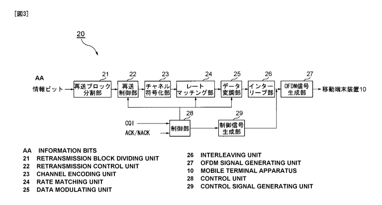
the mobile communication system 1 has. FIG. 3 is a functional
CA 02742159 2011-04-28
16
block diagram of a transmission section that is a principal part
of the base station apparatus 20 that the mobile communication
system 1 has according to this Embodiment. FIG. 4 is a functional
block diagram of a reception section that is a principal part
of the mobile terminal apparatus 10 that the mobile communication
system 1 has according to this Embodiment. In addition, the
configuration of the base station apparatus 20 as shown in FIG.
3 is simplified to explain the invention, and is assumed to have
a configuration including a reception section that a normal base
station apparatus has. Further, the configuration of the mobile
terminal apparatus 10 as shown in FIG. 4 is simplified to explain
the invention, and is assumed to have a configuration including
a transmission section that a normal mobile terminal apparatus
has.
[0025]
As shown in FIG. 3, the transmission section of the base station
apparatus 20 according to this Embodiment has a retransmission
block dividing section 21, retransmission control section 22,
channel coding section 23, rate matching section 24, data
modulation section 25, interleave section 26, OFDM signal
generating section 27, control section 28, and control signal
generating section 29, and is comprised thereof. In addition,
for example, the retransmission section in the scope of claims
includes the retransmission control section 22, OFDM signal
generating section 27 and radio transmission section not shown
CA 02742159 2011-04-28
17
in the figure, and is comprised thereof.
[0026]
In the transmission section of the base station apparatus 20
according to this Embodiment, the retransmission block dividing
section 21 receives information bits constituting a transmission
signal from an upper layer for processing the transmission signal.
Further, the retransmission block dividing section 21 receives,
from the upper layer, instructions (hereinafter, referred to as
"retransmission block division instructions" as appropriate) for
designating the number of retransmission blocks and the
retransmission block size of the transmission signal in
retransmission control in the base station apparatus 20, based
on descriptions of a retransmission block table as described
later.
[0027]
The retransmission block dividing section 21 functions as the
retransmission block dividing section, and divides a transmission
signal into retransmission blocks corresponding to the
retransmission block division instructions from the upper station
apparatus 30. In addition, the retransmission block division
instructions include the number of retransmission blocks (the
number of TBs) and the retransmission block size (BS)
corresponding to the capability (for example, the systembandwidth
capable of being supported, the number of transmission antennas,
etc.) of the mobile terminal apparatus 10 targeted for
CA 02742159 2011-04-28
18
communications. The retransmission block dividing section 21
divides the transmission signal into retransmission blocks
corresponding to the number of retransmission blocks and the
retransmission block size included in the retransmission block
division instructions.
[0028]
Herein, described are descriptions of the retransmission block
table that the base station apparatus 20 refers to in performing
retransmission control according to this Embodiment. FIG. 5 is
a diagram showing an example of the retransmission block table
that the base station apparatus 20 refers to in performing
retransmission control according to this Embodiment. The
retransmission block table as shown in FIG. 5 shows the
relationships between the system bandwidth, the number of
transmission antennas and the number of retransmission blocks,
the retransmission block size, and particularly, shows 20 MHz,
40 MHz, 80 MHz and 100 MHz as the system bandwidth. Further,
the "layer" as shown in FIG. 5 corresponds to the number of
transmission antennas, and the retransmission block size in each
layer indicates the maximum block size in the corresponding system
bandwidth, which is the same as in retransmission tables described
below.
[0029]
With the retransmission block table as shown in FIG. 5 are
registered the numbers of retransmission blocks, the numbers of
CA 02742159 2011-04-28
19
the retransmission blocks are required numbers corresponding to
the number of transmission antennas and the system bandwidth in
the case that the maximum value of the retransmission block size
is fixed to a certain value. Specifically, in the case that the
maximum value of the retransmission block size is fixed to 150, 000
bits that are the maximum retransmission block size in the LTE
specification, with the table are registered the numbers of
retransmission blocks, the numbers of the retransmission blocks
are required numbers corresponding to the number of transmission
antennas and the system bandwidth. More specifically, in the
retransmission block table, the number of retransmission blocks
is set corresponding to the system bandwidth and the number of
transmission antennas, using the number of retransmission blocks,
as a reference, in the case that the number of transmission antennas
is one in 20 MHz that is a base frequency block.
[0030]
When the system bandwidth is 20 MHz, the case of a single
transmission antenna is associated with a single retransmission
block with the retransmission block size of 75,000 bits. The
case of two transmission antennas requires the transmission
capacity two times that in the case of a single transmission antenna,
and is associated with two retransmission blocks of 75,000 bits.
Further, the case of four transmission antennas requires the
transmission capacity four times that in the case of a single
transmission antenna, and is associated with two retransmission
CA 02742159 2011-04-28
blocks of 150,000 bits. Furthermore, the case of eight
transmission antennas requires the transmission capacity eight
times that in the case of a single transmission antenna, and is
associated with four retransmission blocks of 150,000 bits.
5 [0031]
Similarly, when the system bandwidth is 40 MHz, the case of a
single transmission antenna requires the transmission capacity
two times that in the case of a single transmission antenna when
the system bandwidth is 20 MHz, and is associated with a single
10 retransmission block with the retransmission block size of 150,000
bits. The case of two transmission antennas requires the
transmission capacity two times that in the case of a single
transmission antenna, and is associated with two retransmission
blocks of 150,000 bits. Further, the case of four transmission
15 antennas requires the transmission capacity four times that in
the case of a single transmission antenna, and is associated with
four retransmission blocks of 150,000 bits. Furthermore, The
case of eight transmission antennas requires the transmission
capacity eight times that in the case of a single transmission
20 antenna, and is associated with eight retransmission blocks of
150,000 bits.
[0032]
Further, when the system bandwidth is 80 MHz, the case of a single
transmission antenna requires the transmission capacity four
times that in the case of a single transmission antenna when the
CA 02742159 2011-04-28
21
system bandwidth is 20 MHz, and is associated with two
retransmission blocks with the retransmission block size of
150,000 bits. The case of two transmission antennas requires
the transmission capacity two times that in the case of a single
transmission antenna, and is associated with four retransmission
blocks of 150,000 bits. Further, the case of four transmission
antennas requires the transmission capacity four times that in
the case of a single transmission antenna, and is associated with
eight retransmission blocks of 150,000 bits. Furthermore, The
case of eight transmission antennas requires the transmission
capacity eight times that in the case of a single transmission
antenna, and is associated with sixteen retransmission blocks
of 150,000 bits.0
[0033]
Furthermore, when the system bandwidth is 100 MHz, the case of
a single transmission antenna requires the transmission capacity
five times that in the case of a single transmission antenna when
the system bandwidth is 20 MHz, and is associated with three
retransmission blocks with the retransmission block size of
150,000 bits. The case of two transmission antennas requires
the transmission capacity two times that in the case of a single
transmission antenna, and is associated with six retransmission
blocks of 150, 000 bits. Further, the case of four transmission
antennas requires the transmission capacity four times that in
the case of a single transmission antenna, and is associated with
CA 02742159 2011-04-28
22
twelve retransmission blocks of 150,000 bits. Furthermore, the
case of eight transmission antennas requires the transmission
capacity eight times that in the case of a single transmission
antenna, and is associated with twenty-f our retransmission blocks
of 150,000 bits.
[0034]
FIG. 6 shows a conceptual diagram of retransmission blocks
transmitted from the base station apparatus 20 according to the
retransmission block table as shown in FIG. 5. FIG. 6 shows the
case where the number of transmission antennas is eight and the
system bandwidth is 80 MHz (FIG. 6(a)), and the case where the
number of transmission antennas is four and the system bandwidth
is 100 MHz (FIG. 6 (b) ) . As shown in FIG. 6 (a) , when the number
of transmission antennas is eight and the system bandwidth is
80 MHz, the number of retransmission blocks is sixteen, the
retransmission block size is set at 150, 000 bits, and transmission
signals A to P each of 150,000 bits are transmitted from
transmission antennas 1 to 8. Further, as shown in FIG. 6(b),
when the number of transmission antennas is four and the system
bandwidth is 100 MHz, the number of retransmission blocks is twelve,
the retransmission block size is set at 150,000 bits, and
transmission signals A to L each of 150, 000 bits are transmitted
from transmission antennas 1 to 4.
[0035]
The retransmission control section 22 receives the information
CA 02742159 2011-04-28
23
bits associated with the retransmission block divided in the
retransmission block dividing section 21, and performs
retransmission control on a retransmission block basis. In this
case, the retransmission control section 22 outputs the
information bits associated with each retransmission control
block to the channel coding section 23 according to retransmission
timing from the control section 28.
[0036]
The channel coding section 23 performs error correcting coding
on the information bits associated with each retransmission block
received from the retransmission control section 22, and outputs
transmission bits obtained by adding redundant bits to the
information bits to the rate matching section 24. In addition,
to improve efficiency of the decoding processing in the mobile
terminal apparatus 10, the channel coding section 23 is configured
to perform coding by dividing the information bits into a plurality
of coding blocks when the information bits associated with each
retransmission block are a certain size (for example, 6144 bits)
or more.
[0037]
The rate matching section 24 functions as the coding rate adjusting
section, performs repetition and puncturing on the transmission
bits to adjust the coding rate of the information bits (rate
matching processing), and outputs the resultant to the data
modulation section 25. In this case, the repetition and
CA 02742159 2011-04-28
24
puncturing in the rate matching section 24 is performed based
on the coding information notified from the control section 28
corresponding to the content of a retransmission request signal
from the mobile terminal apparatus 10. The rate matching section
24 adjusts the coding rate of the information bits corresponding
to the coding information, and outputs information bits with the
different coding rate to the data modulation section 25. As
specifically described later, the rate matching section 24 thus
adjusts the coding rate of the information bits corresponding
to the coding information associated with the retransmission
request signal from the mobile terminal apparatus 10, it is thereby
possible to adjust the coding rate in retransmission control,
corresponding to an error detection result of the reception signal
in the mobile terminal apparatus 10, and it is possible to achieve
efficient retransmission control.
[0038]
The data modulation section 25 modulates the information bits
input from the rate matching section 24, for example, using a
modulation scheme such as Phase Shift Keying (BPSK, QPSK, 8PSK,
etc.) or Quadrature Amplitude Modulation (QAM) scheme. In this
case, modulation on the information bits in the data modulation
section 25 is performed according to the modulation scheme
notified from the control section 28. The modulation scheme
notified from the control section 28 is selected based on the
CQI (Channel Quality Indicator) notifiedfrom the mobile terminal
CA 02742159 2011-04-28
apparatus 10.
[0039]
The interleave section 26 functions as the interleave section,
rearranges (interleaves) the sequence of the information bits
5 and redundant bits modulated in the data modulation section 25,
and enhances resistance to burst error. In this case, the
interleave section 26 is configured to use the entire system
bandwidth that can be supported by the mobile terminal apparatus
10 targeted for communications to perform interleaving. Herein,
10 described is an example of information bits and redundant bits
interleaved in the interleave section 26 of the base station
apparatus 20 according to this Embodiment.
[0040]
FIG 7 is a schematic diagram to explain an example of information
15 bits and redundant bits rearranged in the interleave section 26
of the base station apparatus 20 according to this Embodiment.
Herein, for convenience in description, as shown in FIG. 7(a),
it is assumed that a single retransmission block is divided into
four coding blocks A to D to undergo error correcting coding.
20 In this case, as shown in FIG. 7(b), the interleave section 26
rearranges the information bits and redundant bits of the coding
blocks A and B using the entire system bandwidth. Similarly,
the interleave section 26 rearranges the information bits and
redundant bits of the coding blocks C and D using the entire system
25 bandwidth. In this case, it is possible to obtain the frequency
CA 02742159 2011-04-28
26
diversity effect in the entire system bandwidth.
[0041]
In addition, conventional interleaving on information bits and
redundant bits is performed on a coding-block basis. In other
words, the interleaving is performed only within the coding block.
Therefore, as shown in FIG. 8, the rearranged information bits
and redundant bits are mapped on a coding-block basis. When the
system bandwidth is a relatively narrow bandwidth, as shown in
FIG. 8, it is possible to perform mapping over a plurality of
unit times. However, when interleaving is performed on a
coding-block basis as described above in the case where the system
bandwidth is extended, as shown in FIG. 9, such an event can occur
that the information bits and redundant bits are mapped only to
part of frequency bands at the unit time. In this case, the
frequency diversity effect can be obtained only in part of the
system bandwidth, and reception characteristics of the reception
signal may deteriorate. Therefore, the interleave section 26
performs interleaving using the entire system bandwidth. By this
means, as compared with the case of performing interleaving only
within the coding block, it is possible to obtain the excellent
frequency diversity effect, and it is possible to enhance
reception characteristics of the reception signal in the mobile
terminal apparatus 10.
[0042]
In the example as shown in FIG 7, for convenience in description,
CA 02742159 2011-04-28
27
the case is shown where the sequence of the information bits and
redundant bits associated with a single retransmission block is
rearranged using the entire system bandwidth. In the case where
a plurality of retransmission blocks exists (for example, in the
case where a retransmission block is assigned for each base
frequency block (20 MHz) in a system having the system bandwidth
of 80 MHz) , the interleave section 26 is configured to be able
to exchange the sequence of information bits and redundant bits
among the retransmission blocks using the entire systembandwidth.
Herein, described is an example of information bits and redundant
bits interleaved in the interleave section 26 when a plurality
of retransmission blocks exists.
[0043]
FIG. 10 is a schematic diagram to explain an example of information
bits and redundant bits rearranged in the interleave section 26
of the base station apparatus 20 according to this Embodiment.
Herein, it is assumed that the system bandwidth is 80 MHz, and
that four retransmission blocks (TBlto TB4) exist in association
with each base frequency block. Further, in FIG. 10, for
convenience in description, the case is shown where each
retransmission block is not divided into a plurality of coding
blocks, but it is naturally possible to apply in the case where
each retransmission block is divided into a plurality of coding
blocks.
[0044]
CA 02742159 2011-04-28
28
FIG. 10(a) shows a state before the rearrangement of the
information bits and redundant bits associated with each
retransmission block. FIG. 10(b) shows the case where the
sequence of the information bits and redundant bits associated
with each retransmission block is spread in the frequency-axis
direction and rearranged. FIG. 10(c) shows the case where the
sequence of the information bits and redundant bits associated
with each retransmission block is spread in the frequency-axis
direction and the time-axis direction and rearranged. FIG. 10(d)
shows the case where the sequence of the information bits and
redundant bits associated with retransmission blocks TB1 and TB2
is spread in the frequency-axis direction and the time-axis
direction within two base frequency blocks and rearranged, while
the sequence of the information bits and redundant bits associated
with retransmission blocks TB3 and TB4 is spread in the
frequency-axis direction and the time-axis direction within two
base frequency blocks and rearranged. In the case that a plurality
of retransmission blocks thus exists, the interleave section 26
is capable of exchanging the sequence of information bits and
redundant bits among retransmission blocks using the entire system
bandwidth, and it is thus possible to obtain the frequency
diversity effect in the entire system bandwidth.
[0045]
The OFDM signal generating section 27 modulates the transmission
signal input from the interleave section 26 with the OFDM scheme,
CA 02742159 2011-04-28
29
together with a control signal generated in the control signal
generating section 29, and generates an OFDM signal. For example,
the OFDM signal generating section 27 performs processing of
subcarrier mapping, IFFT, addition of guard interval, etc. The
OFDM signal generated in the OFDM signal generating section 27
is output to a radio transmission section, not shown, and the
radio signal is transmitted to the mobile terminal apparatus 10.
[0046]
The control section 28 performs entire control of the base station
apparatus 20. Particularly, the control section 28 gives
instructions for retransmission timing to the retransmission
control section 22, while notifying the rate matching section
24 and data modulation section 25 of the information required
for the processing therein. More specifically, the control
section 28 identifies coding information corresponding to ACK
(Acknowledgement) or NACK (Negative Acknowledgement)
constituting a retransmission request signal transmitted from
the mobile terminal apparatus 10, and notifies the rate matching
section 24 of the coding information. Further, the control
section 28 selects a modulation scheme based on the downlink CQI
measured in the mobile terminal apparatus 10, and notifies the
data modulation section 25 of the modulation scheme. Furthermore,
the control section 28 instructs the control signal generating
section 29 to generate a control signal including the coding
information notified to the rate matching section 24 and the
CA 02742159 2011-04-28
modulation scheme notified to the data modulation section 25.
[0047]
The control signal generating section 29 generates a control
signal to transmit to the mobile terminal apparatus 10,
5 corresponding to the instructions from the control section 28.
In addition, this control signal includes the coding information
notified to the rate matching section 24 and the modulation scheme
notified to the data modulation section 25. Further, when the
data modulation section 25 performs MIMO modulation, the control
10 signal also includes the number of spatial multiplexes
corresponding to the number of transmission antennas. The
control signal generated in the control signal generating section
29 is output to the OFDM signal generating section 27, and as
described above, incorporated into part of the OFDM signal, and
15 the radio signal is transmitted to the mobile terminal apparatus
10.
[0048]
Meanwhile, as shown in FIG. 4, the reception section of the mobile
terminal apparatus 10 according to this Embodiment has an OFDM
20 signal demodulation section 11, deinterleave section 12, data
demodulation section 13, rate dematching section 14, channel
decoding section 15, error detecting section 16, control signal
generating section 17, retransmission block combining section
18, and control signal demodulation section 19, and is comprised
25 thereof. In addition, for example, the reception section in the
CA 02742159 2011-04-28
31
scope of claims includes a radio reception section not shown in
the figure, and OFDM signal demodulation section 11, and is
comprised thereof.
[0049]
The OFDM signal demodulation section 11 demodulates the reception
signal, modulated with the OFDM scheme, received from the base
station apparatus 20 via the radio reception section, not shown
in the figure, and extracts a baseband signal. For example, the
OFDM signal demodulation section 11 performs processing of removal
of guard interval, Fourier transform, subcarrier demapping, etc.
on the reception signal, and extracts the data signal and control
signal. The data signal and control signal extracted in the OFDM
signal demodulation section 11 are respectively output to the
deinterleave section 12 and control signal demodulation section
19.
[0050]
The deinterleave section 12 performs deinterleaving on the data
signal input from the OFDM signal demodulation section 11, and
restores the information bits and redundant bits rearranged by
the interleave section 26 of the base station apparatus 20 to
the original sequence. In this case, the deinterleave section
12 beforehand recognizes the content of rearrangement of the
information bits and redundant bits performed by the interleave
section 26 of the base station apparatus 20, and is capable of
properly performing deinterleaving of the received data signal.
CA 02742159 2011-04-28
32
[0051]
The data demodulation section 13 demodulates the data signal input
from the deinterleave section 12, for example, using information
of the modulation scheme such as Phase Shift Keying (BPSK, QPSK,
8PSK, etc.) or Quadrature Amplitude Modulation (QAM) scheme, and
outputs the resultant to the rate dematching section 14. In this
case, demodulation on the data signal in the data demodulation
section 13 is performed according to the information of the
modulation scheme notified from the control signal demodulation
section 19.
[0052]
Further, the data demodulation section 13 has the function as
a MIMO demodulation section. In this case, using the information
of the number of spatial multiplexes and modulation scheme, the
data demodulation section 13 separates the transmission signal
transmitted from each transmission antenna of the base station
apparatus 20 to demodulate, and outputs information bits and
redundant bits included in all the concurrently transmitted
transmission signals to the rate dematching section 14.
[0053]
The rate dematching section 14 deletes informationbits subjected
to repetition, while adding information bits subjected to
puncturing (rate dematching processing) in the data signal input
from the data demodulation section 13, and outputs the resultant
to the channel decoding section 15. In this case, deletion in
CA 02742159 2011-04-28
33
repetition and addition in puncturing in the rate dematching
section 14 is performed base on the coding information notified
from the control signal demodulation section 19. In addition,
this coding information is extracted from the control signal
transmitted from the base station apparatus 20. Therefore, the
rate dematching section 14 is capable of properly deleting the
information bits repeated in the base station apparatus 20, while
properly adding the information bits punctured in the base station
apparatus 20.
[0054]
The channel decoding section 15 performs error correction decoding
on the data signal input from the rate dematching section 14,
and outputs the information bits and redundant bits obtained
thereby to the error detecting section 16. For example, the
channel decoding section 15 is configured to make the soft decision
on each information bit subjected to the rate dematching
processing, and perform error correction decoding using
likelihood values associated with the information bits and
redundant bits constituting the data signal, based on the
likelihood value calculated corresponding to each information
bit.
[0055]
The error detecting section 16 detects an error of the information
bits using an error detecting code such as a CRC (Cyclic Redundancy
Check) code added to the information bits. Particularly, the
CA 02742159 2011-04-28
34
error detecting section 16 is capable of detecting an error on
a basis of a coding block divided from the retransmission block
in the base station apparatus 20. Then, the error detecting
section 16 notifies the control signal generating section 17 of
the result of error detection, while outputting the information
bits to the retransmission block combining section 18 when the
error is not detected.
[0056]
The control signal generating section 17 functions as the
retransmission request signal generating section, and when the
error is detected in the information bits as a result of error
detection, generates a retransmission request signal for feedback
to the base station apparatus 20. The control signal generating
section 17 is capable of generating a retransmission request
signal (ACK, NACK) indicative of the content of a plurality of
kinds of error detection results. The generated retransmission
request signal is transmitted to the base station apparatus 20
from a radio transmission section not shown in the figure. Further,
the control signal generating section 17 also has the function
of receiving a downlink CQI measured in a CQI measuring section,
not shown in the figure, and generating a control signal including
the CQI.
[0057]
Herein, described are details of the retransmission request signal
generated in the control signal generating section 17. FIG. 11
CA 02742159 2011-04-28
is a diagram to explain an example of the retransmission request
signal generated in the control signal generating section 17 of
the mobile terminal apparatus 10 according to this Embodiment.
As shown in FIG. 11, the control signal generating section 17
5 generates retransmission request signals comprised of 2 bits.
Among 2 bits constituting the retransmission request signal, "00"
is assigned ACK, and "O1", "10" and "11" are assigned NACK. Each
of three NACKs is associated with the meaning indicative of a
ratio (ratio of erroneous coding blocks to all the coding blocks)
10 of coding blocks (hereinafter, referred to as "erroneous coding
blocks" as appropriate) erroneously detected in the error
detecting section 16. For example, "01" is associated with the
meaning that the erroneous coding blocks are 1/3 or less, "10"
is associated with the meaning that the erroneous coding blocks
15 are more than 1/3 up to 2/3 or less, and "11" is associated with
the meaning that the erroneous coding blocks are more than 2/3.
[0058]
The control signal generating section 17 generates these
retransmission request signals corresponding to the error
20 detection result in the error detecting section 16, and transmits
the signals to the base station apparatus 20 via the radio
transmission section, not shown. In the base station apparatus
20, when the retransmission request signals are received, the
control section 28 identifies the content of the meaning, and
25 the rate matchingsection24adjuststhe coding rate corresponding
CA 02742159 2011-04-28
36
to the ratio of the erroneous coding blocks indicated by the
retransmission request signal so as to transmit a transmission
packet. For example, as shown in FIG. 11, when ACK ("00") is
received as a retransmission request signal, the section 24
adjusts to the coding rate for new transmission so as to transmit
a transmission packet. Meanwhile, when NACK ("Ol") is received,
the section 24 adjusts to the coding rate for adding the shortest
redundant bits so as to transmit a transmission packet. Further,
when NACK ("10") is received, the section 24 adjusts to the coding
rate for adding the short redundant bits so as to transmit a
transmission packet. Furthermore, when NACK ("11") is received,
the section 24 adjusts to the coding rate for adding the longest
redundant bits so as to transmit a transmission packet. The base
station apparatus 20 is thus capable of transmitting the
transmission packet with the result of error detection in the
mobile terminal apparatus 10 reflected.
[0059]
Thus, in the mobile communication system 1 according to this
Embodiment, themobile terminal apparatus 10 generates aplurality
of kinds of retransmission request signals indicative of ratios
in error detection of the reception signal to transmit to the
base station apparatus 20, and is capable of suitably notifying
the base station apparatus 20 of the ratio in error detection
of the reception signal. Then, corresponding to the
retransmission request signal, the rate matching section 24 in
CA 02742159 2011-04-28
37
the base station apparatus 20 adjusts the coding rate of the
transmission signal, and it is thereby possible to reflect the
ratio in error detection in the transmission signal, and to achieve
efficient retransmission control.
[0060]
The retransmission block combining section 18 functions as the
retransmission block combining section, and combines information
bits input from the error detecting section 16 to restore to the
transmission signal in the state before being divided into
retransmission blocks in the base station apparatus 20. Then,
the retransmission block combining section 18 outputs, as
reception data, the information bits constituting the
transmission signal in the state prior to division to the upper
layer for processing the reception data.
[0061]
The control signal demodulation section 19 demodulates the control
signal input from the OFDM signal demodulation section 11, and
extracts the coding information and modulation scheme included
in the control signal. The section 19 notifies the data
demodulation section 13 of the extracted modulation scheme, while
notifying the rate dematching section 14 of the extracted coding
information. In addition, when the control signal includes the
number of spatial multiplexes corresponding to the number of
transmission antennas in the base station apparatus 20, the
section 19 extracts the number of spatial multiplexes to notify
CA 02742159 2011-04-28
38
the data demodulation section 13.
[0062]
Described next is operation in the case that the base station
apparatus 20 having the above-mentioned configuration
retransmitsa transmission signal to the mobile terminal apparatus
10. FIG. 12 is a sequence diagram to explain the operation in
the case that the base station apparatus 20 retransmits a
transmission signal to the mobile terminal apparatus 10 according
to this Embodiment. In addition, in the sequence as shown in
FIG. 12, described is the processing after the base station
apparatus 20 transmits a transmission signal to the mobile
terminal apparatus 10 according to the normal processing.
Further, for convenience in description, FIG. 12 shows the
sequence simplified to explain the invention, but it is assumed
that the normally required processing is performed when the base
station apparatus 20 retransmits a transmission signal to the
mobile terminal apparatus 10.
[0063]
As shown in FIG. 12, when the base station apparatus 20 transmits
a transmission signal (stepST1101) , the mobile terminal apparatus
10 performs the OFDM signal demodulation processing,
deinterleaving processing, data demodulation processing, rate
dematching processing and channel decoding processing on the
reception signal, and then, the information bits and redundant
bits included in the reception signal are input to the error
CA 02742159 2011-04-28
39
detecting section 16. Then, the error detecting section 16
performs error detection (step ST1102), and outputs the error
detection result to the control signal generating section 17.
In this case, the error detecting section 16 inputs the ratio
of coding blocks (erroneous coding blocks) in which errors are
detected to the control signal generating section 17.
[0064]
Upon receiving the error detection result, the control signal
generating section 17 generates a retransmission request signal
(step ST1103). As described above, the retransmission request
signal is comprised of a control signal of 2 bits of the content
as shown in FIG. 11 based on the error detection result. In this
case, the control signal generating section 17 generates a
retransmission request signal ("00", "01", "10" and "11")
corresponding to the ratio of the erroneous coding blocks to the
coding blocks constituting the reception signal, and the
retransmission request signal is transmitted on uplink to the
base station apparatus 20 (step ST1104).
[0065]
Upon receiving the retransmission request signal, in the base
station apparatus 20, information bits constituting a
transmission signal targeted for a retransmission request are
input to the retransmission block dividing section 21, the
capability (for example, the support-capable system bandwidth,
the number of antennas, etc.) of the mobile terminal apparatus
CA 02742159 2011-04-28
10 that is a transmission source of the retransmission request
signal is determined, and the transmission signal is divided into
retransmission blocks corresponding to the capability (step
ST1105). In this case, the transmission signal is divided into
5 retransmission blocks based on the descriptions of the
retransmission block table shown in FIG. 5 corresponding to the
determined capability of the mobile terminal apparatus 10. In
other words, the transmission signal is divided into
retransmission blocks of the number of retransmission blocks
10 corresponding to the support-capable system bandwidth and the
number of transmission antennas where the maximum retransmission
block size of the retransmission block is 150,000 bits, and it
is thereby possible to avoid events of retransmission blocks
having the retransmission block sizes exceeding 150,000 bits.
15 [0066]
Meanwhile, the control section 28 identifies the coding
information from the content of (ACK or NACK constituting) the
retransmission request signal to input to the rate matching
section 24. Then, the rate matching section 24 performs
20 repetition and puncturing on transmission bits based on the coding
information indicated from the control section 28, and adjusts
the coding rate of the information bits (rate matching processing:
step ST1106). In this case, the coding rate is adjusted
corresponding to the ratio of the erroneous coding blocks detected
25 in the mobile terminal apparatus 10.
CA 02742159 2011-04-28
41
[0067]
After the data modulation processing and interleaving processing
is thus performed on the information bits and redundant bits
obtained in the rate matching processing, the resultant is input
to the OFDM signal generating section 27. Then, the OFDM signal
generating section 27 generates an OFDM signal (step ST1107),
and the OFDM signal is retransmitted to the mobile terminal
apparatus 10 on downlink as a transmission signal (step ST1108)
[0068]
Upon receiving the transmission signal from the base station
apparatus 20, the mobile terminal apparatus 10 performs the OFDM
signal demodulation processing, deinterleaving processing, and
data demodulation processing on the reception signal, and then,
the data signal is input to the rate dematching section 14. The
rate dematching section 14 deletes information bits subjected
to repetition, while adding information bits subjected to
puncturing in the input data signal, based on the coding
information from the base station apparatus 20 demodulated in
the control signal demodulation section 19 (rate dematching
processing: step ST1109). The channel decoding processing is
performed on the data signal subjected to the rate dematching
processing, and then, the information bits and redundant bits
included in the data signal are input to the error detecting section
16. Then, the error detecting section 16performserror detection
(step ST1110).
CA 02742159 2011-04-28
42
[0069]
In addition, herein, it is assumed that the error detecting section
16 does not detect any erroneous coding block. In this case,
the error detecting section 16 inputs the information bits to
the retransmission block combining section 18, and the
retransmission block combining section 18 restores the
retransmission blocks of the transmission signal that is divided
in the base station apparatus 20 (step ST1111) . The information
bits restored to the retransmission blocks prior to division are
output to the upper layer for processing the reception data, and
undergo the predetermined processing. In this way, a series of
processing is finished in the case that the base station apparatus
retransmits a transmission signal to the mobile terminal
apparatus 10.
15 [0070]
Thus, in the mobile communication system 1 according to this
Embodiment, a transmission signal is divided into retransmission
blocks according to a retransmission block table with which are
registered the numbers of the retransmission blocks, each of the
20 transmission blocks is a retransmission unit of a transmission
signal, the numbers of the retransmission blocks are required
numbers corresponding to the number of transmission antennas and
the system bandwidth in case that the maximum value of the size
of the retransmission block is fixed to a certain value,
transmission signals associated with the retransmission blocks
CA 02742159 2011-04-28
43
are retransmitted on downlink, it is thus possible to prevent
a retransmission block having the retransmission block size
exceeding the beforehand determined maximum value to be
retransmitted, and therefore, also in the case that the system
bandwidth is extended, it is possible to suppress deterioration
of retransmission efficiency and to retransmit a transmission
signal efficiently.
[0071]
Particularly, in the mobile communication system 1 according to
this Embodiment, a transmission signal is divided into
retransmission blocks according to the retransmission block table
with the maximum retransmission block size set at 150, 000 bits
that are the maximum retransmission block size in the LTE
specification, it is thereby not necessary to specify a new
definition concerning the retransmission block size with the
LTE-capable mobile terminal apparatus 10, and it is thus possible
to achieve efficient retransmission control while ensuring
compatibility with the already-existing LTE-scheme system.
[0072]
Further, in the mobile communication system 1 according to this
Embodiment, as shown in FIG. 5, in the case of eight or more
transmission antennas, the number of retransmission blocks is
set at four or more. By this means, it is possible to reduce
the number of processing times required for signal separation,
for example, in the case where SIC (Successive Interference
CA 02742159 2011-04-28
44
Controller) is applied as the signal separating method in the
multi-antenna radio transmission technique, and it is possible
to enhance efficiency in the signal separation processing.
[0073]
The present invention is not limited to the above-mentioned Embodiment,
and is capable of being carried into practice with modifications thereof
as appropriate. For example, the processing sections and processing
procedures are capable of being carried into practice with various
modifications thereof as appropriate without departing from the scope
of the invention. Further, the invention is capable of being carried
into practice with modifications thereof as appropriate without departing
from the scope of the invention.
[0074]
For example, the above-mentioned Embodiment describes the case
where the mobile terminal apparatus 10 generates a retransmission
request signal indicative of the ratio (ratio of erroneous coding
blocks) in error detection of the reception signal to transmit
to the base station apparatus 20, and the configuration of the
retransmission request signal is not limited thereto, and is
capable of being modified as appropriate. For example, a
retransmission request signal including the content for
identifying an erroneous coding block may be generated and
transmitted to the base station apparatus 20. In this case, the
base station apparatus 20 is capable of identifying the coding
block in which the transmission error occurs and retransmitting
CA 02742159 2011-04-28
only the coding block, and it is thus possible to actualize more
efficient retransmission control.