Language selection

Search

Patent 2742187 Summary

Third-party information liability

Some of the information on this Web page has been provided by external sources. The Government of Canada is not responsible for the accuracy, reliability or currency of the information supplied by external sources. Users wishing to rely upon this information should consult directly with the source of the information. Content provided by external sources is not subject to official languages, privacy and accessibility requirements.

Claims and Abstract availability

Any discrepancies in the text and image of the Claims and Abstract are due to differing posting times. Text of the Claims and Abstract are posted:

  • At the time the application is open to public inspection;
  • At the time of issue of the patent (grant).
(12) Patent Application: (11) CA 2742187
(54) English Title: DRAINAGE OUTLET FOR INSTALLATION IN A FLOOR OPENING OF A SHOWER STALL
(54) French Title: TUYAU DE VIDAGE A INSTALLER DANS L'OUVERTURE DU PLANCHER D'UNE CABINE DE DOUCHE
Status: Deemed Abandoned and Beyond the Period of Reinstatement - Pending Response to Notice of Disregarded Communication
Bibliographic Data
(51) International Patent Classification (IPC):
  • E03C 01/22 (2006.01)
  • A47K 01/14 (2006.01)
  • E03C 01/26 (2006.01)
  • F16L 55/24 (2006.01)
(72) Inventors :
  • WEDI, STEPHAN (Germany)
(73) Owners :
  • STEPHAN WEDI
(71) Applicants :
  • STEPHAN WEDI (Germany)
(74) Agent: PERLEY-ROBERTSON, HILL & MCDOUGALL LLP
(74) Associate agent:
(45) Issued:
(22) Filed Date: 2011-06-02
(41) Open to Public Inspection: 2011-12-02
Availability of licence: N/A
Dedicated to the Public: N/A
(25) Language of filing: English

Patent Cooperation Treaty (PCT): No

(30) Application Priority Data:
Application No. Country/Territory Date
20 2010 007 534.3 (Germany) 2010-06-02

Abstracts

English Abstract


A drainage outlet for installation in a floor opening of a shower stall The
drainage
outlet includes an inlet part to be inserted in the floor opening that has an
inlet opening
open toward the top, into which a cover element is inserted, the height of
which, inside the
inlet opening, can be adjusted, and which covers the inlet opening while
exposing at least
one level opening. The cover element is rigidly connected, at the underside
thereof, to a
plurality of threaded sleeves, each having an internal thread. Threaded
bushings, each
having an external thread and interior cavity, are screwed adjustably over the
partial
lengths thereof into the internal threads of the threaded sleeves, the
threaded bushings
protruding downwardly from the threaded sleeves The inlet part is provided
with
positioning pins, over which the interior cavities of the threaded bushings
extend. A
threaded sleeve, a threaded bushing, and a positioning pin together form an
adjustment
element.


Claims

Note: Claims are shown in the official language in which they were submitted.

CLAIMS:
1. A drainage outlet for installation in a floor opening of a shower stall,
comprising an
inlet part to be inserted in the floor opening that has an inlet opening open
toward the top,
into which a cover element is inserted, the height of which, inside the inlet
opening, can be
adjusted, and which covers the inlet opening while exposing at least one level
opening,
characterized in that
- the cover element is rigidly connected, at the underside thereof, to a
plurality of
threaded sleeves, each having an internal thread;
- threaded bushings, each having an external thread and interior cavity, are
screwed adjustably over the partial lengths thereof into the internal threads
of the
threaded sleeves, the threaded bushings protruding downwardly from the
threaded
sleeves, and
- the inlet part is provided with positioning pins, over which the interior
cavities of
the threaded bushings extend,
- wherein a threaded sleeve, a threaded bushing, and a positioning pin
together
form an adjustment element
2. The drainage outlet according to claim 1, characterized in that the
positioning pins
are connected to a flange rim of the inlet part.
3. The drainage outlet according to claim 1, characterized in that the cover
element is
provided at least partially with an angled edge flange.
4. A drainage outlet according to claim 1, characterized in that the
positioning pins
have a cylindrically rounded configuration and are tapered toward the top, but
the
threaded bushings extend thereover without play.
5. A drainage outlet according to claim 1, characterized in that the cover
element with
the threaded sleeve is associated with removable threaded bushings (10) that
can be
selected according to the lengths thereof.
6. A drainage outlet according to claim 1, characterized in that, in the case
of a round
inlet opening, at least three adjustment elements are disposed peripherally on
the inlet par
in a radially symmetrical manner.

7. A drainage outlet according to claim 1, characterized in that, with an
inlet opening
in the shape of a longitudinal channel having a U-shaped channel-like inlet
part that is
provided with a bottom, at least two adjustment elements connect the bottom of
the inlet
part to the underside of the elongated cover element.
8. A drainage outlet for installation in a floor opening of a shower stall,
comprising
an inlet part that is insertable into the floor opening that has an inlet
opening open
toward the top, into which a cover element is inserted, the height of which,
inside the inlet
opening, can be adjusted, and which covers the inlet opening while exposing at
least one
level opening,
wherein the cover element is rigidly connected, at the underside thereof, to a
plurality of threaded sleeves each of which has an internal thread,
wherein threaded bushings, each of which has an external thread and interior
cavity, are screwed adjustably over partial lengths thereof into the internal
threads of the
threaded sleeves so that the threaded bushings protrud downwardly from the
threaded
sleeves,
wherien the inlet part includes positioning pins over which the interior
cavities of
the threaded bushings extend, and
wherein one of the threaded sleeves, the threaded bushings, and the
positioning
pins together form an adjustment element.
6

Description

Note: Descriptions are shown in the official language in which they were submitted.


CA 02742187 2011-06-02
Drainage Outlet for Installation in a Floor Opening of a Shower Stall
Background
The invention relates to a drainage outlet for installation in a floor opening
of a
shower stall, comprising an inlet part to be inserted in the floor opening
that has an inlet
opening open toward the top, into which a cover element is inserted, the
height of which
can be adjusted with respect to the inlet opening, and which covers the inlet
opening
while exposing at least one level opening.
A height-adjustable inlet grate is known from EP 1 782 721 (FIG. 8).
An aspect of the invention is to allow for adjustment of the cover element
with
respect to the floor opening and the inlet part, so that a wide variety of
construction
heights can be easily considered, allowing for height adjustment using just a
few parts,
which is easy-to-understand and moreover re-adjustable, and which prevents the
inlet
part from shifting.
The aspect is achieved by a height-adjustable drainage outlet having the
following
characteristics:
- the cover element is rigidly connected, at the underside thereof, to a
plurality of
threaded sleeves, each having an internal thread;
- threaded bushings, each having an external thread and interior cavity, are
screwed adjustably over the partial lengths thereof into the internal threads
of the
threaded sleeves, the threaded bushings protruding downwardly beyond the
threaded
sleeves,
- the inlet part is provided with positioning pins, over which the interior
cavities of
the threaded bushings extend.
Hereinafter, a threaded sleeve, a threaded bushing, and a positioning pin
together
form an adjustment element.
The positioning pins can be connected, for example, to a flange rim of the
inlet
part. Metals are particularly suitable materials for the positioning pins,
however it is also
possible to use synthetic parts.
The cover element can be constructed, for example, as a grate having areal
openings, or as a closed cover element having an angled edge flange, wherein
the outlet
water drains between the edge flange and surrounding parts.
The positioning pin preferably has a cylindrically rounded configuration and
is
tapered toward the top in the tip region, so that no tilting can occur when it
is pulled up,
for example for readjustment.
1

CA 02742187 2011-06-02
It is particularly advantageous to associate the cover element with removable
threaded bushings that can be selected according to the lengths thereof. For
example, a
kit may be supplied, which, without significantly increasing costs, contains
two or more
threaded bushings so as to create greater latitude for the required increase
in height.
The threaded bushing can additionally be locked with a nut.
In the case of a round inlet opening, at least three or four adjustment
elements are
disposed peripherally on the insert part in a radially symmetrical manner.
The embodiment can also be employed for an inlet opening in the shape of a
longitudinal channel having a U-shaped channel-like inlet part that is
provided with a
bottom, wherein at least two adjustment elements connect the bottom of the
inlet part to
the upper part of the elongated cover element or of the channel.
BRIEF DESCRIPTION OF THE DRAWINGS
The present invention will be more readily understood from the detailed
description of embodiments thereof made in conjunction with the accompanying
drawings
of which:
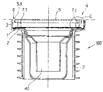
FIG. 1 is a cross-section of a round outlet provided with four adjustment
elements;
FIG. 2 is a bottom view of a round cover element comprising the adjustment
elements;
FIGS. 3a to 3c show possible adjustments, in the sectional view according to
FIG.
1 (detail C); and
FIG. 4 is a sectional view of an adjustment element.
DETAILED DESCRIPTION
Reference will now be made in detail to embodiments of the present invention,
examples of which are illustrated in the accompanying drawings, wherein like
reference
numerals refer to the like elements throughout, The embodiments are described
below to
explain the present invention by referring to the figures.
The terms "top" and "bottom" used hereinafter are defined by the conventional
arrangement of an inlet in the illustration of the shower outlet that is
shown, which is to
say with the cover element at the "top" and the inlet opening at the "bottom".
However, it
should be noted that the parts of the adjustment element described hereafter
may also be
disposed in reverse order from "bottom to top".
FIG. 1 shows a cross-section of an embodiment of a drainage outlet 100 for
installation in a floor opening 4 of a shower stall,
2

CA 02742187 2011-06-02
The drainage outlet 100 is always kept open. An inlet part 1 is recessed in
the
floor opening 4 and rests with the flange collar 2 on the widened upper edge
of a pipe
socket 3, in which an odor trap 40 and a lateral outlet pipe (not shown) are
located. The
part of the drainage outlet 100 located beneath the floor opening 4 does not
form part of
the invention and may therefore also be designed in a different manner.
Above the flange rim 2, a cover element 5 is inserted in the stepped floor
opening
4. In the present case, the cover element is configured in the shape of a
round disk and
provided with a flange rim 5.1. However, it is also possible to configure such
a cover
element as a grate, which ends in a planar manner at the rim. In both cases, a
"level
opening" 6 is obtained, into which the water can flow and drain downward.
Oval, rectangular or polygonal cover element units can also be accordingly
provided with an adjustment device described hereinafter.
Four adjustment elements 7.1, 7.2, 7.3 and 7.4, by which the height of the
cover
element 5 can be adjusted with respect to the flange collar 2, are connected
to the upper
side of the flange rim 2 of the inlet part 1. As is shown in the sectional
view according to
FIG. 4, a plurality of positioning pins 8 are fastened in an upwardly
extending manner on
a flange collar 2, for example by way of welding or bonding. The positioning
pins 8 are
made of brass or other corrosion-resistant materials and are configured in a
tapered
manner toward the top; they are smooth on the outside.
The opposing underside 5.2 of the cover element 5 is provided with four
threaded
sleeves 9 comprising internal threads 9.1. The threaded sleeve 9 has a height
of h1. A
threaded bushing 10 comprising an external thread 10.2 and interior cavity
10.1 is
screwed over part of the length thereof into the internal thread 9.1 of the
threaded sleeve
9. The threaded bushing 10 has a length of 11 ~ h1 and thus protrudes downward
beyond
the threaded sleeve 9, even if screwed in partially.
The interior cavity 10.1 of the partially screwed-in threaded bushing 10 is
pushed
over a positioning pin 8 until the lower edge of the threaded bushing 10 abuts
the flange
collar 2. This establishes the height of the cover element 5 with respect to
the inlet part 1.
To lock the position of the threaded bushing 10 with respect to the threaded
sleeve 9, a
nut 11 can further be screwed onto the threaded bushing 10. For this purpose,
fixable
nuts are preferably selected.
The cover element 5 can be lifted out of the floor opening 4 as needed, in
particular to clean the drainage outlet. It is also easily possible to
readjust the height.
Lifting off the cover element is facilitated, because tilting with respect to
the positioning
pin 8 is prevented by the design.
3

CA 02742187 2011-06-02
FIGS. 3a to 3c schematically illustrate a detail C according to FIG. 1 at
different
height adjustments. Using threaded bushings 10, and notably threaded bushings
10
having different lengths, it is possible to set multiple height and distance
ranges between
the cover element 5 and inlet part 1. Continuous adjustment is possible.
FIG. 3a shows that the threaded sleeve 9 can be pushed onto the positioning
pin
8 with the threaded bushing completely screwed in. This applies, for example,
with a
standard distance from the flange 2 to the underside 5.1 of 15 mm, for
example. In the
embodiment according to FIG. 3b, a threaded bushing 10 having a length of 14
mm is
screwed in, so that a total distance range of approximately 15 to 25 mm is
covered in this
case.
If instead of the threaded bushing having a length of 14 mm, one measuring 22
mm is used (FIG. 3c), an adjustment range of 25 to 37 mm is obtained.
Depending on the requirements, it is also possible to select additional
threaded
bushings, or those having other dimensions.
In the overall, this facilitates the use of cover elements having varying
heights with
respect to the inlet part, in keeping with the floor and outlet configuration.
To this end, the
solution according to the invention can be employed both for round and
elongated-
channel shaped drainage outlets.
Although selected embodiment(s) of the present invention has/have been shown
and described, it is to be understood the present invention is not limited to
the described
embodiment(s). Instead, it is to be appreciated that changes may be made to
this/these
embodiment(s) without departing from the principles and spirit of the
invention, the scope
of which is defined by the claims and the equivalents thereof.
4

Representative Drawing
A single figure which represents the drawing illustrating the invention.
Administrative Status

2024-08-01:As part of the Next Generation Patents (NGP) transition, the Canadian Patents Database (CPD) now contains a more detailed Event History, which replicates the Event Log of our new back-office solution.

Please note that "Inactive:" events refers to events no longer in use in our new back-office solution.

For a clearer understanding of the status of the application/patent presented on this page, the site Disclaimer , as well as the definitions for Patent , Event History , Maintenance Fee  and Payment History  should be consulted.

Event History

Description Date
Time Limit for Reversal Expired 2017-06-02
Application Not Reinstated by Deadline 2017-06-02
Inactive: Abandon-RFE+Late fee unpaid-Correspondence sent 2016-06-02
Deemed Abandoned - Failure to Respond to Maintenance Fee Notice 2016-06-02
Application Published (Open to Public Inspection) 2011-12-02
Inactive: Cover page published 2011-12-01
Inactive: IPC assigned 2011-09-29
Inactive: First IPC assigned 2011-09-29
Inactive: IPC removed 2011-09-29
Inactive: IPC assigned 2011-09-06
Inactive: Filing certificate - No RFE (English) 2011-06-20
Application Received - Regular National 2011-06-20
Small Entity Declaration Determined Compliant 2011-06-02

Abandonment History

Abandonment Date Reason Reinstatement Date
2016-06-02

Maintenance Fee

The last payment was received on 2015-05-28

Note : If the full payment has not been received on or before the date indicated, a further fee may be required which may be one of the following

  • the reinstatement fee;
  • the late payment fee; or
  • additional fee to reverse deemed expiry.

Patent fees are adjusted on the 1st of January every year. The amounts above are the current amounts if received by December 31 of the current year.
Please refer to the CIPO Patent Fees web page to see all current fee amounts.

Fee History

Fee Type Anniversary Year Due Date Paid Date
Application fee - small 2011-06-02
MF (application, 2nd anniv.) - standard 02 2013-06-03 2013-05-23
MF (application, 3rd anniv.) - small 03 2014-06-02 2014-05-22
MF (application, 4th anniv.) - small 04 2015-06-02 2015-05-28
Owners on Record

Note: Records showing the ownership history in alphabetical order.

Current Owners on Record
STEPHAN WEDI
Past Owners on Record
None
Past Owners that do not appear in the "Owners on Record" listing will appear in other documentation within the application.
Documents

To view selected files, please enter reCAPTCHA code :


To view images, click a link in the Document Description column. To download the documents, select one or more checkboxes in the first column and then click the "Download Selected in PDF format (Zip Archive)" or the "Download Selected as Single PDF" button.

List of published and non-published patent-specific documents on the CPD .

If you have any difficulty accessing content, you can call the Client Service Centre at 1-866-997-1936 or send them an e-mail at CIPO Client Service Centre.


Document
Description 
Date
(yyyy-mm-dd) 
Number of pages   Size of Image (KB) 
Description 2011-06-01 4 201
Claims 2011-06-01 2 74
Abstract 2011-06-01 1 23
Drawings 2011-06-01 4 62
Representative drawing 2011-10-19 1 11
Filing Certificate (English) 2011-06-19 1 157
Reminder of maintenance fee due 2013-02-04 1 112
Courtesy - Abandonment Letter (Request for Examination) 2016-07-13 1 163
Courtesy - Abandonment Letter (Maintenance Fee) 2016-07-13 1 171
Reminder - Request for Examination 2016-02-02 1 116
Fees 2013-05-22 1 156
Correspondence 2011-06-19 1 51
Fees 2014-05-21 1 24
Fees 2015-05-27 1 25