Note: Descriptions are shown in the official language in which they were submitted.
CA 02742221 2012-11-02
INTEGRAL ELECTRIC MOTOR WITH SPEED SENSOR, PLANETARY GEARBOX AND
STEERING MEANS
FIELD OF THE INVENTION
The invention relates generally to electrical wheel motor drive systems for
small compact
construction equipment.
BACKGROUND OF THE INVENTION
United States Patent No. 6,852,061, issued February 8, 2005. FIGS. 1-3 are
substantial
duplicates from U.S. Patent Number 6,852,061. Fig. I is a perspective view 100
of a pair of wheel motors
in accordance with the prior art interconnected by a tie bar used for
steering. Fig. 2 is a front view 200 of
a wheel motor in accordance with the prior art. Fig. 3 is a side, partially
cross-sectional view 300 taken
along line 3-3 of Fig. 2 in accordance with the prior art. Fig. 3A is a side,
partially cross-sectional view
300A, of another embodiment of the prior art.
United States Patent No. 6,852,061, issued February 8, 2005, states as
follows:
"With respect to FIG. 1, two wheel motor assemblies 10 are shown in a paired
relationship with
an interconnecting tie bar assembly 12 which is pivotably connected at each
end to spindle brackets 14.
Spindle brackets 14 are pivotably mounted on a shaft (not shown) extending
downwardly from brackets
16. Brackets 16 can be mounted to the appropriate undercarriage of the scissor
lift or other scaffold
equipment (not shown). Tie bar assembly 12 is connected to the steering
mechanism of the equipment
(not shown) so that the tie bar can be moved laterally to cause the wheel
motor assemblies to pivot around
the shaft to steer the equipment.
With reference to FIGS. 2 and 3, wheel motor assembly 10 comprises spindle
bracket 14 to which
is mounted motor 18. The upper end 15 of spindle bracket 14 has a hollow
cylindrical opening 20 formed
1
CA 02742221 2011-06-06
throughout which is dimensional (sic, dimensioned) to receive the cylindrical
shaft (not shown) mounted
on bracket 16 so that the spindle bracket 14 can pivot about vertical axis 22.
Electrical power is supplied to motor 18 through electrical cable 24 which is
connected to an
appropriate power source. The application of electrical power through cable 24
causes output shaft 26 or
motor 18 to rotate. Output shaft 26 is supported for rotation by shaft bearing
28 positioned within a
circular opening 29 through the lower end 57 of spindle bracket 14. An O-ring
seal 30 is provided around
the edge of motor 18 to prevent dust and debris from entering the motor
compartment and to support the
motor 18. Additionally, a shaft lip seal 32 is provided to further seal the
shaft 26 to prevent lubricant from
exiting and dust and debris from entering the gear compartment 31. Gear
compartment 31 comprises a
hollow interior portion of the lower end 57 of spindle bracket 14. Shaft
bearing 28 is retained in position
by a retaining ring 34. Mounted on the end of output shaft 26 is input sun
gear 36 which is retained on the
end of shaft 26 by a retaining ring 38 which engages a recess on the end of
shaft 26. Sun gear 36
comprises a plurality of gear teeth which engage corresponding gear teeth on
input planet gears 40 (only
one of three shown). A ring gear 42 having a plurality of gear teeth is
positioned to engage the teeth of
input planet gears 40 so that rotation of the input sun gear 36 causes the
input planet gears 40 to rotate
within ring gear 42 to cause the input planet gears to circle around sun gear
36. Planet gears 40 are
mounted for rotation on input planet pins 44 by lock ring 41, and are
supported for rotation about input
planet pins 44 by needle bearings 43. Pins 44 are mounted to an input carrier
46 which is joined to output
sun gear 48. Input carrier 46 is locked to output sun gear 48 by a locking
ring 49. Sun gear 48 is mounted
for rotation around shaft 26. Thus, when input planetary gears 40 are caused
to circle about sun gear 36 as
sun gear 36 rotates, carrier 46 and joined output sun gear 48 are caused to
rotate about shaft 26 in the
same direction.
Output sun gear 48 has teeth which engage gear teeth on output planet gears 50
which are
mounted for rotation to the spindle bracket 14 by output planet pins 52.
Thrust washers 54 are provided
2
CA 02742221 2011-06-06
on each side of output planet gears 50 around pin 52 and needle bearings 56
support the output planet
gears 50 for easy rotation.
Mounted for rotation about lower end 57 of spindle bracket 14 is generally
cylindrically shaped
hub 58. Hub 58 is supported for rotation by bearings 60 and 62. Bearings 60
are retained in position by
retaining ring 61. Joined to the interior surface 59 of hub 50 is an output
ring gear 64 which engages
output planet gears 50. Rotation of the output planet gears 50 caused by the
rotation of the output sun gear
48 causes the output ring gear 64 to rotate causing joined hub 58 to rotate.
Thus, the application of
electrical power to motor 18 causes output shaft 26 and attached input sun
gear 36 to rotate which in turn
causes input planet gears to rotate around the interior of ring gear 42 which
in turn rotates input carrier 46
and attached output sun gear 48 about shaft 26. The rotation of output sun
gear 48 in turn causes output
planet gears 50 to rotate which in turn causes output ring gear 64 and
integrally joined hub 58 to rotate. A
rubber wheel (not shown) is normally attached to the exterior surface 55 of
hub 58 by bolts (not shown)
screwed into threaded recesses 66 formed on a vertical face 68 of hub 58.
A cover 70 overlies the open exterior end of hub 58 and is retained in
position by a locking ring
72 which engages a groove at the open exterior end of hub 58. An O-ring seal
74 is positioned around the
edge of cover 70 to prevent lubricant from exiting and dust and construction
debris from entering the
planetary gear compartment 31. Also, a lip seal 76 is provided around the
interior edge of hub 58 and the
edge of spindle bracket 14 to prevent lubricant from exiting and dust and
construction debris from
entering the interior of the mechanism from the back side.
Electric motor 18 has a braking mechanism 79 contained at the exterior end of
motor 18 and is
covered by cover 78. The braking mechanism operates to lock shaft 26 to
prevent rotation of shaft 26
when electrical power is removed from motor 18 but to release shaft 26 for
rotation whenever electrical
power is applied to motor 18. This locking mechanism prevents movement of the
wheels any time
electrical power is not being applied. Thus, if wheel motor assembly 10 is
used to drive a scissor lift or
3
CA 02742221 2011-06-06
other scaffolding type equipment, such equipment is locked and prevented from
movement once the
electrical power is removed from motor 24."
SUMMARY OF THE INVENTION
An assembly for moving construction lifts and scaffold equipment is disclosed
and claimed. The
assembly includes first and second steerable wheel motor assemblies for moving
construction lifts and
scaffold equipment. Each of the first and second steerable wheel motor
assemblies for moving
construction lifts and scaffold equipment includes a spindle bracket
configured to be pivotably mounted
at an upper end to a steering mechanism for rotation about a vertical axis.
Each of the assemblies further
includes an electric motor mounted to a lower end of the spindle bracket. The
motor has an output shaft
that rotates about an axis when electrical power is supplied to the motor. The
output shaft is positioned
through a shaft opening into an interior portion of the lower end of the
spindle bracket.
The output shaft is supported by a first set of bearings and a second set of
bearings. The first set
of bearings resides within the electric motor and the second set of bearings
resides between the spindle
bracket and the output shaft. The second set of bearings includes a speed and
direction sensor integral
therewith for detecting the speed and direction of rotation of the output
shaft.
The second set of bearings includes an inner race and an outer race. The inner
race is affixed to
the output shaft and rotatable therewith and the outer race is stationary. A
magnetized impulse ring is
affixed to the inner race and is rotatable therewith. A sensor body is affixed
to the outer race of the second
set of bearings which detects the magnetic impulses provided when the inner
impulse ring and the shaft
are rotating. A substantially cylindrical wheel hub is mounted to the spindle
bracket for rotation about a
horizontal axis coincident with the axis of rotation of the output shaft.
The wheel hub includes an exterior surface to which a wheel can be mounted, an
interior surface
surrounding the interior portion of the lower end of the spindle bracket, an
interior edge between the
exterior and interior surfaces, and, an exterior edge between the exterior and
interior surfaces. The hub is
4
CA 02742221 2011-06-06
supported for rotation by a third set of bearings positioned adjacent the
interior edge of the hub, and a
fourth set of bearings positioned inwardly from the exterior edge of the hub.
A multi-stage planetary gear system is mounted around the output shaft of the
motor and
positioned within the interior portion of the spindle bracket and within the
cylindrical wheel hub between
the exterior edge and the interior edge. The planetary gear system includes an
input sun gear positioned
between the fourth set of bearings and the exterior edge of the hub and
mounted on the output shaft of the
motor.
The input sun gear includes a proximate portion and a distal portion. The
planetary gear system
further includes input planetary gears, a first ring gear affixed to the
interior portion of the wheel hub, an
input gear carrier including a splined interior, and, an output sun gear
including a splined exterior. The
output sun gear includes a proximate portion and a distal portion. A thrust
washer resides between the
spindle bracket and the proximate end of the output sun gear. The proximate
portion of the output sun
gear interengages the thrust washer and the distal portion of the output sun
gear interengages the
proximate portion of the input sun gear.
An end cover is affixed to the wheel hub and is rotatable therewith. The end
cover of the wheel
hub includes a centrally located cylindrical recess therein. A circumferential
spacer ring and a
circumferential bracket reside in the cylindrical recess in the cover. The
distal portion of the input sun
gear interengages the circumferential bracket in the cylindrical recess in the
cover.
The input sun gear rotationally drives the input planetary gears which are in
engagement with
and react against the first ring gear producing rotation of the input gear
carrier. The splined interior of the
input gear carrier interengages the splined exterior of the output sun gear.
The planetary gear system
further includes output planetary gears driven by the splined exterior of the
output sun gear. The output
planetary gears are mounted for rotation with respect to the spindle.
An output ring gear is positioned between the third set of bearings and the
fourth set of bearings
5
CA 02742221 2011-06-06
and joined to the interior surface of the wheel hub. The output ring gear
engages the output planetary
gears of the multistage planetary gear system so that rotation of the output
planetary gears causes the
output planetary gears and the wheel hub to rotate such that mechanical force
through the planetary gear
system is applied to the wheel hub.
The speed and direction sensor which is integral with the second set of
bearing unit outputs two
square wave signals. A signal processor adapts the square wave signals for
input into the microprocessor.
The microprocessor receives the adapted square wave signals. An operator input
station applies the
desired wheel hub speed and direction to the microprocessor. The
microprocessor receives the adapted
square wave signals and compares the square wave signals to the desired wheel
hub speed and direction
input signals and outputs a corrective control signal according to an
algorithm, Any number of algorithms
may be used and the algorithms may be used to protect the motor. The
microprocessor, sometimes
referred to herein as an embedded microcontroller or embedded microprocessor,
protects the motors.
A motor controller receives and processes the corrective control signal from
the microprocessor
and outputs a control signal to the electric motor dictating the speed and
direction of the output shaft.
One of the main benefits of a speed sensor in mobile applications is that it
allows for closed-loop
motor control. This allows for fine tuning the voltage delivered to the motor
armature based on the speed
measured by the sensor, so that the motor speed will exactly match the target
(command) speed. The
speed sensor also provides means of protection to the motor. The controller
can detect if there is a locked
rotor condition and will stop delivering power to the motor. Without the speed
sensor the controller could
continue to deliver power to the motor until the motor burned up. Speed
sensors can be used in a variety
of different control scenarios some of which would be application dependent.
Speed sensors may be used
for traction control or to ensure that braking or acceleration is done at
specific rate or within a specific
distance. Speed sensors may also be used as an odometer and/or speedometer.
A thrust washer between the spindle and the output sun gear allows control of
the output sun gear
6
CA 02742221 2011-06-06
and input carrier end play more precisely. Use of the thrust washer controls
the end play of the output
sun gear without requiring precise machining of the shaft within the motor and
thus reduces cost and
complexity in the electric motor. Use of the thrust washer enables proper
fitting of the output sun gear
within the required space. Without the use of the thrust washer, due to
manufacturing tolerance buildup,
the output sun gear may either be too loose or it may be too tight.
The interengagement of the proximate portion of the output sun gear with the
thrust washer, the
interengagement of the distal portion of the output sun gear with the
proximate portion of the first sun
gear, and the interengagement of the distal portion of the input sun gear with
the circumferential bracket
in the cylindrical recess in the cover controls the position of the output sun
gear axially.
Use of the thrust washer eliminates the need to control the distance between a
first shoulder 301
and a second shoulder of the output shaft. Shoulder on output shaft must
reside at the precise location
distally with respect to the motor or another location on the output shaft.
Put another way, shoulder on
shaft must be located precisely with respect to spindle. The location of
shoulder is important as a
corresponding shoulder engages shoulder of output shaft and rotates with
respect to output shaft . The
precise location of shoulder on shaft determines whether the generally
cylindrically shaped output sun
gear fits correctly in the allotted space. If the shoulder is located at the
proper axial location the output
sun gear will fit properly. If the axial location of shoulder is located too
far from shoulder, then the
output sun gear will fit too tightly between shoulder and the proximate end of
input sun gear. If the axial
location of shoulder is not located far enough from shoulder, then output sun
gear will fit too loosely
between shoulder and the proximate end of input sun gear. Reference numeral
indicates a seal residing
between the output shaft and spindle adjacent washer.
A steerable wheel motor assembly for moving construction lifts and scaffold
equipment is
disclosed and claimed which includes a spindle bracket configured to be
pivotably mounted at an upper
end to a steering mechanism for rotation about a vertical axis. The output
shaft is supported by a first set
7
CA 02742221 2011-06-06
of bearings and a second set of bearings with the second set of bearings
including a speed and direction
sensor integral therewith for detecting the speed and direction of rotation of
the output shaft. The sensor
outputs to a control system which controls the speed and direction of the
equipment. A thrust washer is
used to position the output sun gear accurately reducing manufacturing and
maintenance costs of the
assembly. Use of the thrust washer reduces the cost of machining the output
shaft to a high tolerance.
It is an object of the present invention to provide an output shaft being
supported by a first set of
bearings and a second set of bearings wherein the second set of bearings
resides between the spindle
bracket and the output shaft and wherein the second set of bearings includes a
speed and direction sensor
integral therewith for detecting the speed and direction of rotation of the
output shaft.
It is a further object of the present invention to provide a second set of
bearings which includes an
inner race and an outer race with the inner race being affixed to the output
shaft and rotatable therewith
and the outer race being stationary.
It is a further object of the present invention to provide a second set of
bearings wherein a
magnetized impulse ring is affixed to the inner race and is rotatable
therewith and wherein a sensor body
is affixed to the outer race of the second set of bearings which detects the
magnetic impulses provided
when the inner impulse ring and the shaft are rotating.
It is a further object of the present invention wherein a speed and direction
sensor outputs two
square wave signals, a signal processor adapts the square wave signals for
input into a microprocessor, the
microprocessor receives the adapted square wave signals, and then compares the
adapted process signals
with respect to the desired wheel hub speed and direction.
It is a further object of the present invention wherein the microprocessor
receives the adapted
square wave signals and compares the square wave signals to the desired wheel
hub speed and direction
input signals and outputs a corrective control signal according to an
algorithm.
It is a further object of the present invention wherein any number of
algorithms may be used and
CA 02742221 2011-06-06
the algorithms may be used to protect the motor.
It is a further object of the present invention wherein a motor controller
receives and processes
the corrective control signal from the microprocessor and outputs a control
signal to the electric motor
dictating the speed and direction of the output shaft.
It is a further object of the present invention wherein the speed sensor is
used for closed-loop
motor control which allows fine tuning the voltage delivered to the motor
armature based on the speed
measured by the sensor so that the motor speed will nearly exactly match the
target (command) speed.
It is a further object of the present invention to provide a speed sensor in
combination with a
microprocessor as a means of protection to the motor.
It is a further object of the present invention to provide a speed sensor in
combination with a
microprocessor as a means of limiting acceleration and deceleration.
It is a further object of the present invention to provide a speed sensor in
combination with a
microprocessor to be used as a speedometer or odometer.
It is a further object of the present invention to provide a thrust washer
between the spindle and
the output sun gear which allows control of the output sun gear and input
carrier end play more precisely.
It is a further object of the present invention to provide a thrust washer so
as to lessen the need for
precise machining of the shaft within the motor and without the motor thus
reducing cost and complexity
in the electric motor.
It is a further object of the present invention to: interengage the proximate
portion of the output
sun gear with the thrust washer, to interengage the distal portion of the
output sun gear with the proximate
portion of the first sun gear, and to intcrengage the distal portion of the
input sun gear with the
circumferential bracket in the cylindrical recess in the cover, thus
controlling the axial position of the
output sun gear.
BRIEF DESCRIPTION OF THE DRAWINGS
9
CA 02742221 2011-06-06
Fig. 1 is a perspective view of a pair of wheel motors in accordance with the
prior art
interconnected by a tie bar used for steering.
Fig. 2 is a front view of a wheel motor in accordance with the prior art.
Fig. 3 is a side, partially cross-sectional view taken along line 3-3 of Fig.
2 in accordance with the
prior art,
Fig. 3A is a side partially cross-sectional view of another embodiment of the
prior art,
Fig. 4 is a cross-sectional view of the invention illustrating the speed
sensor bearing unit, the
thrust washer, the output sun gear abutting the thrust washer and the output
shaft.
Fig. 4A is an enlargement of a portion of Fig. 4.
Fig. 4B is a perspective view of the speed sensor bearing unit mounted on the
output shaft.
Fig. 4C is a schematic of the microprocessor, speed and direction control
sensors, the signal
processors, the motor controllers the motors and the respective outputs for
both of the wheels.
DESCRIPTION OF THE INVENTION
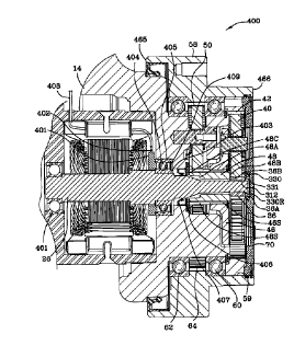
Fig. 4 is a cross-sectional view 400 of the invention illustrating the speed
sensor bearing unit 401,
the thrust washer 406, the output sun gear 48 abutting the thrust washer 406
and the output shaft 26. An
assembly 10 includes first and second steerable wheel motor assemblies for
moving construction lifts and
scaffold equipment. Each of the first and second steerable wheel motor
assemblies for moving
construction lifts and scaffold equipment includes a spindle bracket 14
configured to be pivotably
mounted at an upper end 15 to a steering mechanism for rotation about a
vertical axis 22. Each of the
assemblies further includes an electric motor 18 mounted to a lower end of the
spindle bracket. The motor
has an output shaft 26 that rotates about an axis when electrical power is
supplied to the motor. The
output shaft is positioned through a shaft opening into an interior portion of
the lower end of the spindle
bracket 14.
The output shaft is supported by a first set of bearings 461 and a second set
of bearings 401. The
CA 02742221 2011-06-06
first set of bearings 461 resides within the electric motor between the motor
housing and the shaft 26.
Fig. 4B is a perspective view 400B of the speed sensor bearing unit 401
mounted on the output
shaft 26. The second set of bearings 401 resides between spindle bracket 14
and output shaft 26. The
second set of bearings 401 includes a speed and direction sensor integral
therewith for detecting the speed
and direction of rotation of the output shaft 26.
The second set of bearings 401 includes an inner race 403 and an outer race
405 and a plurality of
ball bearings 404. Inner race 403 is affixed to the output shaft 26 and
rotatable therewith and outer race
405 is stationary. A magnetized impulse ring 413 is affixed to the inner race
403 and is rotatable
therewith as shaft 26 rotates. A sensor body 414 is affixed to the outer race
405 of the second set of
bearings 401 which detects the magnetic impulses provided when the inner
impulse ring 413 and the shaft
26 are rotating. A cable 402, 408 leads from the sensor 401 to communicate
with a control system
illustrate in Fig. 4C. Reference numeral 408 indicates the external portion of
the cable which extends
from the motor housing as illustrated in Fig. 4.
The sensor-bearing units 401 are specially designed incremental encoders for
motor control and
they are produced by SKF Mechatronics. The SKF Mechatronics sensor is being
set forth herein by way
of example only and many different sensors and different types of sensors may
be used. The sensor-
bearing units 401 provide compact and reliable encoding which is subsequently
processed and then used
in a control system. The sensor-bearing units employed herein are intended for
applications with a
rotating inner ring and stationary outer ring.
The sensor bearing unit 401 incorporates an active sensor designed to be
compact and resides
very close to an incremental encoder. The sensor's main components are the
impulse ring, the sensor
body with the sensors and the connecting cable. The composite magnetized
impulse ring is attached to the
stationary bearing inner race which is divided into a certain number of north
and south poles. The sensor
body is attached to the bearing outer race. The sensor body has two sensing
cells for measuring and
11
CA 02742221 2011-06-06
counting the rotation of the shaft in two different rotational directions. The
sensor requires an external
voltage supply. The sensor outputs two different square waves and depending on
which signal is leading,
the direction of rotation is determined and the speed of rotation of is
determined.
A substantially cylindrical wheel hub 58 is mounted to the spindle bracket 14
for rotation about a
horizontal axis coincident with the axis of rotation of the output shaft 26.
The wheel hub includes an
exterior surface 55 to which a wheel can be mounted, an interior surface 59
surrounding the interior
portion of the lower end of the spindle bracket 14, an interior edge 465
between the exterior 58 and
interior 59 surfaces, and, an exterior edge 466 between the exterior 58 and
interior 59 surfaces. The hub
58 is supported for rotation by a third set of bearings 62 positioned adjacent
the interior edge 466 of the
hub, and a fourth set of bearings 60 positioned inwardly from the exterior
edge 465 of the hub.
A multi-stage planetary gear system is mounted around the output shaft 26 of
the motor and
positioned within the interior portion of the spindle bracket 14 and within
the cylindrical wheel hub 58
between the exterior edge 466 and the interior edge 465. The planetary gear
system includes an input sun
gear 36 positioned between the fourth set of bearings 60 and the exterior edge
466 of the hub 58 and
mounted on the output shaft 26 of the motor. Input sun gear 36 includes an
exterior spline which engages
exterior spline 412 of output shaft 26.
Input sun gear 36 includes a proximate portion 36B and a distal portion 36A.
Input sun gear 36 is
sometimes referred to herein as a "first" sun gear. Proximate refers to the
side (or point) closest the motor
and distal refers to the side (or point) farthest from the motor. The
planetary gear system further includes
input planetary gears 40, a first ring gear 61 affixed to the interior portion
of the wheel hub 58, an input
gear carrier 46 including a splined interior 46A, and, an output sun gear 48
including a splined exterior
48S. Sometimes herein, the input planetary gears 40 are referred to as the
first planetary gears. Also,
sometimes herein the input gear carrier 46 is referred to as the first
carrier.
The output sun gear 48 includes a proximate portion 48C and a distal portion
48B. The output sun
12
CA 02742221 2011-06-06
gear is mounted for rotation about the output shaft. A thrust washer 406
resides between the spindle
bracket 14 and the proximate end 48C of the output sun gear 48. The proximate
portion 48C of the
output sun gear 48 interengages the thrust washer 406 and the distal portion
48B of the output sun gear 48
interengages the proximate portion 36B of the input sun gear 36.
An end cover 70 is affixed to the wheel hub 58 and is rotatable therewith. The
end cover of the
wheel hub includes an interior, the interior includes a centrally located
cylindrical recess 330R therein. A
circumferential spacer ring 330 and a circumferential bracket 331 reside in
the cylindrical recess 330R in
the cover. The distal portion 36A of the input sun gear 36 interengages the
circumferential bracket 331 in
the cylindrical recess 330R in the cover.
The interengagement of the proximate portion 48C of the output sun gear with
the thrust washer
406, the interengagement of the distal portion 48B of the output sun gear 48
with the proximate portion
36B of the first sun gear 36, and the interengagement of the distal portion
36A of the input sun gear with
the circumferential bracket 331 in the cylindrical recess 330R in the cover
controls the position of the
output sun gear axially.
Referring to Fig. 3A, use of the thrust washer eliminates the need to control
the distance between
a first shoulder 301 and a second shoulder 302 of the output shaft 26. Still
referring to Fig. 3A, shoulder
301 on output shaft 26 must reside at the precise location distally with
respect to the motor or another
location on the output shaft. Put another way, shoulder 301 on shaft 26 must
be located precisely with
respect to spindle 14. The location of shoulder 301 is important as a
corresponding shoulder 48A of
output sun gear 48 engages shoulder 301 of output shaft 26 and rotates with
respect to output shaft 26.
The precise location of shoulder 301 on shaft 26 determines whether the
generally cylindrically shaped
output sun gear 48 fits correctly in the allotted space. If the shoulder 301
is located at the proper axial
location the output sun gear 48 will fit properly. If the axial location of
shoulder 301 is located too far
from shoulder 302, then the output sun gear will fit too tightly between
shoulder 301 and the proximate
13
CA 02742221 2011-06-06
end 36B of input sun gear 36. If the axial location of shoulder 301 is not
located far enough from
shoulder 302, then output sun gear 48 will fit too loosely between shoulder
301 and the proximate end
36B of input sun gear 36.
Use of the thrust washer 406 positioned between spindle 14 and output sun 48
provides a
reference (the spindle) which is accurate and reliable. Output sun gear 48
reliably fits within the allocated
axial space between washer 406 and proximate end 36B of input sun gear 36.
Tolerances of output sun
gear 48, washer 406, input sun gear 36 and bracket 331 ensure proper fitting
of output sun gear 48
between washer 406 and sun gear 36. Use of the washer 406 greatly improves
operation of the gear
system by reducing the end play of the output sun gear 48,
The input sun gear 36 rotationally drives the input planetary gears 40 which
are in engagement
with and react against the first ring gear 42 producing rotation of the input
gear carrier 46. The splined
interior 46A of the input gear carrier 46 interengages the splined exterior
48S of the output sun gear 48.
The planetary gear system further includes output planetary gears 50 driven by
the splined exterior 48S of
the output sun gear 48S.
The output planetary gears are mounted for rotation with respect to the
spindle bracket such that
rotation of the output sun gear causes the output planetary gears to rotate.
Reference numeral 407
indicates a seal residing between the output shaft 26 and spindle 14 adjacent
washer 406.
An output ring gear 64 joined to the interior of the wheel hub is positioned
between the third set
of bearings 62 and the fourth set of bearings 60 and is joined to the interior
surface 59 of the wheel hub.
The output ring gear 64 engages the output planetary gears 50 of the
multistage planetary gear system so
that rotation of the output planetary gears 50 causes output ring gear 64 and
the wheel hub 58 to rotate
such that mechanical force through the planetary gear system is applied to the
wheel hub.
Fig. 4C is a schematic 400C of the microprocessor 450, speed and direction
control sensors 401,
431, the signal processors 420, 440, the motor controllers 422, 442 , the
motors 423, 443 and the
14
CA 02742221 2011-06-06
respective outputs for both wheels. Fig. 4C illustrates the operation of a 2
wheel drive system. Four
wheel drive systems are specifically contemplated. The speed and direction
sensors 401, 431 output two
square wave signals 401A, 431A, 401 B, 431 B which are out of phase as
designated by phase angle, a,
(REFERENCE NUMERAL 499) with respect to each other. The direction of shaft 26
is determined by
the relationship between the output signals 401A, 401B of the bearing unit
sensor. A signal processor
420, 440 adapts the square wave signals for input into the microprocessor 450.
The microprocessor 450
receives the adapted square wave signals. An operator input station applies
the desired wheel hub speed
490 and direction 491 to the microprocessor 450. The microprocessor 450
receives the adapted square
wave signals 420A, 440A and compares the square wave signals to the desired
wheel hub speed 490 and
direction 491 input signals and outputs a corrective control signal 450A, 450B
according to an algorithm.
Any number of algorithms may be used and the algorithms may be used to protect
the motor and to
protect the operator of the equipment. The microprocessor 450, sometimes
referred to herein as an
embedded microcontroller or embedded microprocessor, protects the motors.
A motor controller 422, 442 receives and processes the corrective control
signal 450A, 450B
from the microprocessor 450 and outputs a control signal 422A, 442A to the
electric motor 423, 442
dictating the speed and direction of the output shaft. Sensors 401, 431 detect
the speed and direction
423F, 443F of the motor 423, 443.
Reference Numerals
10- two wheel motor assemblies
12- interconnecting tie bar assembly
14- spindle brackets
15- upper end of spindle bracket 14
16- bracket
CA 02742221 2011-06-06
18- motor
22- vertical axis
24- cable
26- output shaft
28- shaft bearing
29- circular opening
30- O-ring seal
31- gear compartment
32- lip seal
34- retaining ring
36- input sun gear
36A- distal end of input sun gear 36
36B- proximate end of input sun gear 36
38- retaining ring
40- input planet gear
41- lock ring
42- ring gear
43- needle bearings
44- input planet pins
46- input carrier
46S-splincd interior of input carrier 46
48- output sun gear
48A- proximate shoulder on output sun gear 48
48B- distal end of output sun gear abutting 36B, the proximate end of input
sun gear
16
CA 02742221 2011-06-06
48C- proximate end of output sun gear 48
48S- splined exterior of output sun 48
49- locking ring
50- output planet gears
52- pins
54- thrust washers
55- exterior surface of hub 50
56- needle bearings
57- lower end of spindle bracket 14
58- generally cylindrically shaped hub
59- interior surface of hub 50
60- bearings
62- bearings
64- output ring gear
70-cover
72- locking ring
74- O-ring seal
76- lip seal
78- cover
79-braking mechanism
100- perspective view of a pair of wheel motors in accordance with the prior
art interconnected by a tie
bar used for steering
200- a front view of a wheel motor in accordance with the prior art.
300- a side, partially cross-sectional view taken along line 3-3 of Fig. 2 in
accordance with the prior art
17
CA 02742221 2011-06-06
300A- side partially cross-sectional view of another embodiment of the prior
art
301- shoulder on shaft 26 which abuts shoulder 48A on output sun gear
302- shoulder on drive shaft 26 within the electric motor
305- shoulder on spindle 14 for engagement of bearing 28
330- circumferential spacer
330R- centrally located recess
331- circumferential bracket
400- cross-sectional view of the invention illustrating the speed sensor
bearing unit, the thrust washer, the
output sun gear abutting the thrust washer and the drive shaft.
400A- enlargement of a portion of Fig. 4
400B- perspective view of the speed sensor bearing unit mounted on the drive
shaft
400C- schematic of the microprocessor, speed and direction control sensors,
the signal processors the
signal controllers the motor controllers the motors and the respective outputs
for both of the
wheels
401, 431- bearing/speed sensor
401A, 431A -signal A
40111, 432A -signal B
499- ct, phase between signal 401A and 40111, determines direction of shaft
402- cable leading from the speed sensor
403- inner, rotating, race of the bearing/speed sensor affixed to shaft 26
404- ball bearings
405- outer, stationary, race of the bearing/speed sensor engaging spindle 24
406- thrust washer
407- seal
18
CA 02742221 2012-11-02
408- external portion of cable 402
409- bearing/speed sensor seal
412- spline on output shaft 26
413- magnetized impulse ring
414- sensor body
420, 440- signal processor
420A, 440A- processed signal
422, 442- motor controller
422A, 442A- motor controller output
423, 443- motor
423F, 443F- actual motor speed
450- microprocessor
450A, 450B- microprocessor output
461- first set of standard bearings
465- interior edge of hub 58
466- exterior edge of hub 58
490- setpoint, desired input speed
491- setpoint, desired input direction
492- speedometer
493- odometer
19