Note: Descriptions are shown in the official language in which they were submitted.
CA 02742456 2013-05-16
21519-749
1
CONTAINER WITH INTEGRATED STRUCTURAL REINFORCEMENT
[01]
BACKGROUND OF THE INVENTION
[02] The invention relates generally to containers, such as those in the
configuration of
packages and tubs, which may or may not have a lid. More specifically, the
present
invention relates to such containers that are used to store articles, such as
food.
[03] It is well known in the art that containers are commonly used to store
food, but it
should be understood that the invention relates to any type of container for
any type of
purpose.
[04] For many types of containers, there is a desire to make the structure,
including the
walls, as rigid as possible. However, there needs to be some additional
elements or
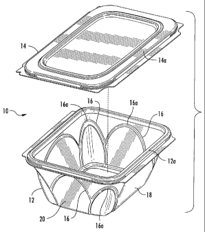
materials to achieve this, which adds cost. For example, it is common to
include carbon
fiber or metal reinforcement members, which not only adds complexity to the
manufacturing process but also adds significant cost. Also, it is possible to
simply make the
walls of the container thicker, which, similarly, adds costs in view of the
use of additional
material usage. Thus, there is a balancing between amount and nature of
material used
and the rigidity of the container. This is particularly true with containers
that are made of
plastic material using a forming process, such as thermoforming or injection
molding.
[05] In view of the above, the prior art attempts in the prior art are not
adequate as they
add undesirably complexity and cost to the manufacture of these containers.
CA 02742456 2013-05-16
21519-749
=
2
[06] In view of the foregoing, there is a demand for a container that is
the same as or less
expensive than prior art containers yet are more rigid with an increased
resistance to top
load which allows for an increase in stack weight on the top of the container
or tub.
[07] There is a need for a container that uses less material with thinner
walls yet provides
superior rigidity for increased top load capability, i.e. ability to support
larger weight with
more items stacked thereon.
SUMMARY OF THE INVENTION
[08] The present invention preserves the advantages of prior art containers
and tubs. In
addition, it provides new advantages not found in currently available
containers and tubs
and overcomes many disadvantages of such currently available containers and
tubs.
[09] The invention is generally directed to the novel and unique container
(i.e. a tub) that
can support a higher top load yet has thinner walls so that less material can
be used yet
the increased resistance to top load can still be achieved.
[10] More specifically, the present invention provides a structurally
reinforced container
that incrudes a base having a bottom, side walls, corners and a top peripheral
edge
defining an open top end. A plurality of ridges formed in at least one of the
side walls and
corners. The ridges are in the configuration of at least one arch having an
apex where the
apex of the at least one arch is proximal to the open top end of the base. A
lid resides in
communication with the top peripheral edge of the base to releasably close the
top end of
the base. As a result, the arches provide reinforcement to the base of the
container to
increase top load resistance.
[1.1.] Many different configurations of the present invention are
possible. It is possible
that at least one arch is provided on each of the side walls and the corners.
It is also
CA 02742456 2011-06-06
3
possible that the base has four side walls and four corners and one arch is
located on each
side wall and each corner of the base. The arches may or may not overlap and
may be in
any number.
[12] It is therefore an object of the present invention to provide a
container that has
increased resistance top load weight.
[13] Another object of the present invention is to provide a container that
has thinner
walls than prior art containers yet still provides top load resistance.
[14] A further object of the present invention is to provide a container
that includes an
engineered geometry so that superior top load capability can be achieved with
thinner
material walls.
BRIEF DESCRIPTION OF THE DRAWINGS
[15] The novel features which are characteristic of the present invention
are set forth in
the appended claims. However, the invention's preferred embodiments, together
with
further objects and attendant advantages, will be best understood by reference
to the
following detailed description taken in connection with the accompanying
drawings in
which:
[16] Fig. 1 is a front perspective view of the container, with base and
lid, of the present
invention;
[17] Fig. 2 is a front view of the container of Fig. 1;
[18] Fig. 3 is a side view of the container of Fig. 1;
[19] Fig. 4 is a top perspective view of the base of the container of Fig.
1;
[20] Fig. 5 is a top view of the base of the container of Fig. 1; and
Ref: E034 P02176-US1
CA 02742456 2011-06-06
4
[21] Fig. 6 is a side elevational view of a number of containers of the
present invention in
a stacked formation.
DETAILED DESCRIPTION OF THE PREFERRED EMBODIMENT
[22] Referring first to Fig. 1, the container 10 of the present invention
is shown to include
a base 12 and a lid 14. In accordance with the present invention, a number of
arches 16
are integrated into the wall geometry of the base 12 where the apex 16a of the
arches 16
receives the downward forces from the weight of any object stacked on the top
thereof.
The arches 16 are formed by creating ridges in the wall using thermoforming
techniques,
such as providing the appropriate tooling to create such ridges, where
desired. The
present invention incorporates the structural advantages of arches, such as in
bridges, into
a container for improving the structural integrity thereof.
[23] The lid 14 is provided on the top of the base 12 of the container 10,
with the items
to be stored residing therein, such as food or the like (not shown).
Preferably, the lid 14
snaps onto the base for engagement of the peripheral top edge 12a of the base
12 with
peripheral edge 14a of the lid 14 to provide a seal. Further details of such
interconnection
need not be discussed herein as these interconnections are very well known in
the art.
[24] In the example shown in the figures, the container 10 of the present
invention is
generally rectangular in shape so one side 18 is longer than the other 20. To
illustrate this,
Fig. 2 shows a front elevational view of the longer side 18 while Fig. 3 shows
an elevational
view of the short side 20. This rectangular configuration is just one example
of how the
present invention can be used. For example, the container 10 can be formed
into a square,
round, oval or other shapes depending on the need and application at hand.
Still further,
Ref: E034 P02176-US1
CA 02742456 2011-06-06
the integrated arches 16 can be seen in Fig. 4, which is a top perspective
view of the
container 10, and Fig. 5, which is a top view of the container 10.
[25] When a single container 10 is sitting by itself on a support surface,
there are
essentially no downward forces exerted onto to the top of the lid 14 to the
walls 18, 20 of
the base 12 of the container 10. However, there is frequently a desire to
stack multiple
containers 10 on top of each other, as seen in Fig. 6. Such a stacked
arrangement is
common during shipping and display of the containers 10 at the point of sale.
The higher
the stack, more and more weight is placed on the container walls 16, 18, as
seen by the
downward facing arrows, making it more difficult to resist the top loading,
particularly for
the containers 10 at the bottom of the stack.
[26] More specifically, downward forces as seen by the downward facing
arrows, from
another container 10 or other object, are exerted on the top of the lid 14 and
distributed
thereacross and to the side walls 16, 18. If the side walls 16, 18 cannot
support the top
load that is being delivered, they will collapse and the container will fail
risking damage to
the contents. The integrated arches 16, with the apex of each arch 16a at the
top and
proximal to the open top end of the base 12, make the walls 16, 18 more rigid,
namely in
the downward direction onto the edge of the wall 16, 18, which is the general
direction of
the vector forces received as a result of weight being placed on the top of
the lid and
container.
[27] The present invention is superior to prior art containers in that is
can achieve
increased top loading (i.e. stacking weight form above) even though its walls
16, 18 are
thin and devoid of added reinforcements, such carbon fiber. For example, the
walls 16, 18
may be as thin as 10 mil in thickness, which may be a preferred thickness. The
improved
Ref: E034 P02176-US1
CA 02742456 2011-06-06
6
structural integrity is achieved by engineering the wall geometries to include
integral
reinforcement structures so that the increased top loading can still be
achieved, even with
the thinner walls 16, 18. This enables weight to be saved. As seen in Fig. 6,
additional
structural integrity is provided, as generally referenced by arrows B, to
support the added
weight, as referenced by arrows A.
[28] The present invention preferably uses an array of overlapping arches
16. However,
this is just one example of the many different types of arch configurations
and arrays that
can be employed. For example, it is preferred that there is one arch 16 at
each corner and
another for each side for a total of eight arches 16 when the container 10 is
four-sided. Of
course, this can be modified to suit the overall configuration of the
container 10 and
desired amount of additional rigidity. For example, more or less arches 16 can
be provided
than the number of sides 16, 18 and corners 22, as can best be seen in Fig. 5.
Also, for
round containers, any desired number of arches 16 could be used. The arches 16
are
preferably arcuate in configuration and can extend transversely any desired
distance. Such
a spanning distance depends on the size and shape of the final container 10
and the
regions of the container 10 that are in need of top load structural
reinforcement.
[29] Further, while it is preferred that the arches 16 overlap and
generally extend from
the top edge 12a of the container to the bottom edge 12b of the container, it
is possible
that the arches 16 do not overlap at all and also do not extend from the top
edge 12a to
the bottom edge 12b of the side 16, 18 of the container 10. As above, the
arrangement
and configuration of the arches 16 may be modified to suit the purpose of the
container 10
and its desired level of rigidity. Also, the depth, namely the amount/extent
of the profiling
Ref: E034 P02176-US1
CA 02742456 2013-05-16
1
21519-749
7
of the plastic or depth of the ridges can be changed to further achieve the
desired level of
rigidity.
[30] In addition to the providing additional structural top loading
reinforcement, the use
of the arches 16 also improves the overall appearance of the container 10. The
arches 16
shown in the figures are merely an example of such ornamental arches. However,
these
arches 16 need not be the same in appearance as what is shown to achieve the
desired
structural reinforcement. As stated above, the arches 16 can be modified
significantly and
still be within the scope of the present invention.
[31] The container 10 of the present invention is particularly well suited
for
thermoforming containers 10 out of plastic, which may be transparent,
translucent or
opaque. Thermoforming, using the appropriate tooling, is so well known in the
art that it
need not be discussed in detail herein. Suffice it to say that the tooling
would be
appropriately manufactured to provide the desired wall profiling to achieve
the ridged arch
formations 16. Containers 10 made out of other materials by other methods can
also be
achieved using the present invention.
[32] It would be appreciated by those skilled in the art that various
changes and
modifications can be made to the illustrated embodiments without
departing.from the
present invention. All such modifications and changes are intended to be
covered by the present invention and any appended claims.