Note: Descriptions are shown in the official language in which they were submitted.
CA 02742706 2011-05-04
WO 2010/053973
PCT/US2009/063251
EXPLOITATION OF DEFORMATION MECHANISMS FOR
INDUSTRIAL USAGE IN THIN PRODUCT FORMS
Field of Invention
[0001] The present application relates to mechanisms for plasticity at room
temperature which
may arise from spinodal glass matrix microconstituent structures in a glass
forming matrix. The
resulting alloys may be formed in relatively thin product forms such as fiber,
ribbon, wire, and thin
sheet (i.e. foil) and may be utilized for a wide variety of industrial usages.
Background
[0002] Metals are understood to exhibit primarily nondirectional
metallic bonds, which allow
bonds to break under the application of a stress/load and then reform allowing
metals the ability to
have intrinsic ductility and the ability to deform plastically.
Mechanistically, metals may deform at
room temperature primarily through the movement of dislocations. Dislocations
may be
understood as one-dimensional type defects which can exhibit edge, screw, or
mixed character and
move by breaking the bonds of individual atoms one at a time resulting in a
displacement of the
atoms by one Burgers vector. Dislocations are found to move on their slip
systems, which
depending on the specific crystal structure and space group, may involve
specific planes and
specific crystallographic directions.
[0003] It may be appreciated that in ionically bonded ceramic materials,
dislocations can also
play a role in deformation. However, these classes of materials have bonds
which may be
directional and involve transfer of electrons and the formation of specific
ions. Thus, after a
particular bond is broken, this places positive ions next to positive ions or
negative ions next to
negative ions and the repulsion forces make it difficult to reform the bonds.
Thus, due to the high
strength of the ceramic bonds, ceramic materials can exhibit a relatively high
hardness and strength
which often are superior to that found in metals. However, ceramic materials
may generally be
brittle with an inherent inability to deform plastically.
[0004] Nanocrystalline metallic materials may also offer relatively high
strength and hardness.
Nanocrystalline materials may be understood to be, by definition,
polycrystalline structures with a
1
CA 02742706 2011-05-04
WO 2010/053973
PCT/US2009/063251
mean grain size below 100 nm. They have been the subject of widespread
research since the mid-
1980s when it was argued that metals and alloys, if made nanocrystalline,
would have a number of
appealing mechanical characteristics of potential significance for structural
applications. But
despite relatively attractive properties (high hardness, yield stress and
fracture strength), it is well
known that nanocrystalline materials may generally show a disappointing and
very low tensile
elongation and tend to fail in an extremely brittle manner. In fact, the
decrease of ductility for
decreasing grain sizes has been known for a long time as attested, for
instance, by the empirical
correlation between the work hardening exponent and the grain size as proposed
for cold rolled and
conventionally recrystallized mild steels. As the grain size is progressively
decreased, the
formation of dislocation pile-ups may become more difficult and their movement
is quite limited by
the large amount of 2-d defect phase and grain boundaries. Thus, with the
development of
nanocrystalline grains, the achievement of adequate ductility (> 1%) has been
a challenge.
[0005] Metallic glasses are a class of materials which may exhibit
characteristics which are
both metallic like since they contain non-directional metallic bonds, metallic
luster, and significant
electrical and thermal conductivity, and ceramic like since relatively high
hardness is often
obtained coupled with brittleness and the lack of tensile ductility. Amorphous
metallic alloys (i.e.,
metallic glasses) represent a relatively young class of materials, having been
first reported in 1960
when classic rapid-quenched experiments were performed on Au-Si alloys. Since
that time, there
has been remarkable progress in exploring glass forming alloy compositions,
seeking elemental
combinations with ever-lower critical cooling rates for the retention of an
amorphous structure.
Metallic glasses are understood to be supercooled liquids which may exist in
solid form at room
temperature but have structures which are relatively similar to what is found
in the liquid with
relatively short range order present. Metallic glasses may have free
electrons, exhibit metallic
luster, and exhibit metallic bonding similar to what is found in conventional
metals. All metallic
glasses may be considered metastable materials and when heated up, they will
transform into
crystalline state. The process is called crystallization or devitrification.
Since diffusion is limited
at room temperature, enough heat (i.e. Boltzman's Energy) needs to be applied
to overcome the
nucleation barrier to cause a solid-solid state transformation which is caused
by glass
devitrification. The devitrification temperature of metallic glasses can vary
widely, commonly
from 300 to 800 C with enthalpies of crystallization commonly from -25 to -250
J/g. The
2
CA 02742706 2011-05-04
WO 2010/053973
PCT/US2009/063251
devitrification process can occur in one or multiple stages. When occurring in
multiple stages, a
crystalline phase may be formed and then depending on the specific partition
coefficient, atoms
may either be attracted to the new crystallites or rejected into the remaining
volume of the glass.
This may result in a more stable glass chemistry which may necessitate
additional heat input to
cause partial or full devitrification. Thus, partially devitrified structures
can result in crystalline
precipitates in a glass matrix. Commonly, these precipitates may be in the
size range of 30 to 125
nm. Full devitrification to a completely crystalline state may result from
heat treating above the
highest temperature glass peak which can be revealed through thermal analysis
such as differential
scanning calorimetry or differential thermal analysis.
[0006] Due to the extremely fine length scale of the structural order
(i.e. molecular
associations) and near defect free nature of the material (i.e. no 1-d
dislocation or 2-d grain / phase
boundary defects), relatively high strength (and correspondingly hardness) may
be obtained which
can be on the order of 33 to 45% of theoretical. However, due to the lack of
crystallinity,
dislocations may not be found and so far there is does not appear to be a
mechanism for significant
(i.e. > 2%) tensile elongation. Metallic glasses may exhibit relatively
limited fracture toughness
associated with the rapid propagation of shear bands and/or cracks which may
be a concern for the
technological utilization of these materials. While these materials may show
adequate ductility by
testing in compression, when testing in tension they may exhibit elongations
very close to zero and
fracture in the brittle manner. The inherent inability of these classes of
material to be able to
deform in tension at room temperature may be a relatively limiting factor for
potential structural
applications where intrinsic ductility may be needed to avoid catastrophic
failure.
[0007] Owing to strain softening and/or thermal softening, plastic
deformation of metallic
glasses may be relatively highly localized into shear bands, resulting in a
relatively limited plastic
strain (less than 2%) and catastrophic failure at room temperature. Different
approaches have been
applied to enhanced ductility of metallic glasses including: introducing
heterogeneities such as
micrometer-sized crystallites, nanometer-sized crystallites, glassy phase
separation, or by
introducing free volume in amorphous structure. The heterogeneous structure of
these composites
may act as an initiation site for the formation of shear bands and/or a
barrier to the rapid
propagation of shear bands, which may result in enhancement of global
plasticity in compression
and sometimes a corresponding decrease in the strength. Recently, a number of
metallic glasses
3
CA 02742706 2011-05-04
WO 2010/053973
PCT/US2009/063251
have been fabricated in which the plasticity was attributed to stress-induced
nanocrystallization or a
relatively high Poisson ratio. It should be noted, that with these approaches,
metallic glasses may
exhibit enhanced plasticity during compression tests (12-15%) but their
tensile elongation may not
exceed 2%. Very recent results on improvement of tensile ductility of metallic
glasses was
.. published when 13% tensile elongation was achieved in a zirconium based
alloys with large
dendrites (20-50 p m in size) embedded in glassy matrix. It should be noted
that this material is
primarily crystalline and might be considered as a microcrystalline alloy with
residual amorphous
phase along dendrite boundaries. The maximum strength of these alloys as
reported is 1.5 GPa.
Thus, while metallic glasses are known to exhibit favorable characteristics of
relatively high
.. strength and high elastic limit, their ability to deform in tension may be
extremely limited which
severely limits the industrial utilization of this class of materials.
Summary
[0008] In one aspect, the present disclosure relates to a glass forming
alloy. The glass forming
alloy may include 43.0 atomic percent to 68.0 atomic percent iron, 10.0 atomic
percent to 19.0
.. atomic percent boron, 13.0 atomic percent to 17.0 atomic percent nickel,
2.5 atomic percent to 21.0
atomic percent cobalt, optionally 0.1 atomic percent to 6.0 atomic percent
carbon, and optionally
0.3 atomic percent to 3.5 atomic percent silicon. The glass forming alloy may
include between 5 %
to 95 % by volume one or more spinodal glass matrix microconstituents which
may include one or
more semi-crystalline and/or crystalline phases at a length scale less than 50
nm in a glass matrix.
Furthermore, the alloy may be capable of blunting shear bands through
localized deformation
induced changes under tension.
[0009] In another aspect, the present disclosure relates to a method of
forming spinodal
microconstituents in a glass forming alloy. The method may include melting
alloy constituents
including 43.0 atomic percent to 68.0 atomic percent iron, 10.0 atomic percent
to 19.0 atomic
percent boron, 13.0 atomic percent to 17.0 atomic percent nickel, 2.5 atomic
percent to 21.0 atomic
percent cobalt, optionally 0.1 atomic percent to 6.0 atomic percent carbon,
and optionally 0.3
atomic percent to 3.5 atomic percent silicon to form an alloy, and forming and
cooling the alloy
wherein upon cooling the glass forming alloy includes between 5 % to 95 % by
volume one or
more spinodal microconstituents comprising one or more semi-crystalline and/or
crystalline phases
.. at a length scale less than 50 nm in a glass matrix capable of blunting
shear bands through localized
deformation induced changes under tension.
4
CA 02742706 2011-05-04
WO 2010/053973
PCT/US2009/063251
Brief Description of Drawings
[0010]
The above-mentioned and other features of this disclosure, and the manner of
attaining
them, will become more apparent and better understood by reference to the
following description of
embodiments described herein taken in conjunction with the accompanying
drawings, wherein:
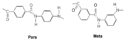
Figure 1 illustrates the chemical structure of para-aramid and meta-aramid
polymers.
Figure 2 illustrates two para-aramid molecules cross linked together by
hydrogen bonding.
Figure 3 illustrates an example of polyethylene molecular structure.
Figure 4 illustrates DTA curves of the following alloys melt spun at 10.5 m/s;
wherein FIG.
4a) illustrates a DTA curve for PC7E8S1A1, FIG. 4b) illustrates a DTA curve
for PC7E8S1A2,
FIG. 4c) illustrates a DTA curve for PC7E8S1A3, FIG. 4d) illustrates a DTA
curve for
PC7E8S1A4, FIG. 4e) illustrates a DTA curve for PC7E8S1A5, and FIG. 40
illustrates a DTA
curve for PC7E8S1A6.
Figure 5 illustrates typical example ribbons which were bent 180 showing the
4 types of
bending behavior; FIG. 5a) illustrates alloy PC7e8 melt-spun at 10 m/s showing
Type 1 Behavior,
FIG. 5b) illustrates alloy PC7e8S1A7 melt-spun at 10.5 m/s showing Type 2
Behavior, FIG. Sc)
illustrates alloy PC7e8S1A14 melt-spun at 10.5 m/s showing Type 3 Behavior,
and FIG. 5d)
illustrates alloy PC7e8S1A9 melt-spun at 10 m/s exhibiting Type 4 Behavior.
Figure 6 illustrates an example of a tensile stress-strain curve for
PC7E8S1A1X4 ribbon
melt spun at 10.5 m/s.
Figure 7 illustrates an example of a tensile stress-strain curve for
PC7E8S1A1X6 ribbon
melt spun at 10.5 m/s.
Figure 8 illustrates an example of a tensile stress-strain curve for
PC7E8S1A1X12 ribbon
melt spun at 10.5 m/s.
Figure 9 provides a summary of tensile strength vs tensile elongation for a
wide variety of
material classes including the best new data from the SGMM alloys.
Figure 10 illustrates an example of a melt-spun run which was produced at 10.5
m/s and is
essentially one long ribbon.
Figure 11 illustrates DTA curves of the PC7E8S1A9 alloy melt-spun at 39, 30,
16, 10.5, 7.5
and 5 m/s.
Figure 12 illustrates DTA curves of the PC7E9S1A1X6 alloy melt-spun at 10.5,
7.5, and 5
m/s.
5
CA 02742706 2011-05-04
WO 2010/053973
PCT/US2009/063251
Figure 13 illustrates TEM micrographs of the microstructures and SAED patterns
for the
PC7E8S1A9 ribbons; including the microstructure (FIG. 13a) and corresponding
SAED pattern
(FIG. 13b) for the wheel side, and microstructure (FIG. 13c) and the
corresponding SAED pattern
(FIG. 13d) for the central region.
Figure 14 illustrates TEM micrograph of the localized deformation induced
changes (LDIC)
around a shear band; wherein FIG. 14a) illustrates microstructure changes
inside and around the
shear band in areas A,B, and C, FIG. 14b) illustrates phase transformation
revealed by the changes
in the selected area electron diffraction (SAED) patterns in areas A, B, and
C.
Figure 15 illustrates localized shear deformation induced crystal growth in
the region ahead
of the growing shear band tip. The nanocrystalline particles with increased
sizes are revealed in
FIG. 15b) for the selected region D indicated in FIG. 15a) using a rectangle.
Figure 16 illustrates an SEM secondary electron micrograph of the PC7E7w16
fracture
surface.
Figure 17 illustrates an SEM secondary electron micrograph of the PC7E7w16
fracture
surface.
Figure 18 illustrates an SEM secondary electron micrograph of the PC7E8S8A6w16
fracture surface.
Figure 19 illustrates a stress-strain curve of the PC7E8S1A9 ribbon, which was
subsequently examined by scanning electron microscopy (SEM).
Figure 20 illustrates SEM micrographs of arrested cracks under uniform tension
loading;
FIG. 20a) illustrates the edge crack is arrested, FIG. 20b) illustrates the
crack deflecting and
macroscale branching, FIG. 20c) illustrates crack deflecting and microscale
branching.
Figure 21 illustrates SEM micrographs of underdeveloped edge cracks; FIG. 21a)
illustrates
a crack arrested at a very initial growing stage, and FIG. 21b) illustrates a
crack deflecting and
branching at a sub-micron scale.
Detailed Description
[0011]
The present application relates to glass forming chemistries which may lead to
Spinodal
Glass Matrix Microconstituent (SGMM) structures which may exhibit relatively
significant
ductility and high tensile strength.
Spinodal microconstituents may be understood as
microconstituents formed by a transformation mechanism which is not nucleation
controlled. More
6
CA 02742706 2011-05-04
WO 2010/053973
PCT/US2009/063251
basically, spinodal decomposition may be understood as a mechanism by which a
solution of two
or more components (e.g. metal compositions) of the alloy can separate into
distinct regions (or
phases) with distinctly different chemical compositions and physical
properties. This mechanism
differs from classical nucleation in that phase separation occurs uniformly
throughout the material
and not just at discrete nucleation sites. One or more semicrystalline
clusters or crystalline phases
may therefore form through a successive diffusion of atoms on a local level
until the chemistry
fluctuations lead to at least one distinct crystalline phase. Semi-crystalline
clusters may be
understood herein as exhibiting a largest linear dimension of 2 nm or less,
whereas crystalline
clusters may exhibit a largest linear dimension of greater than 2nm. Note that
during the early
stages of the spinodal decomposition, the clusters which are formed may be
relatively small and
while their chemistry differs from the glass matrix, they are not yet fully
crystalline and have not
yet achieved well ordered crystalline periodicity. Additional crystalline
phases may exhibit the
same crystal structure or distinct structures. Furthermore the glass matrix
may be understood to
include microstructures that may exhibit associations of structural units in
the solid phase that may
be randomly packed together. The level of refinement, or the size, of the
structural units may be in
the angstrom scale range (i.e. 5A to 100 A).
[0012] In addition, the alloys may exhibit Induced Shear Band Blunting
(ISBB) and Induced
Shear Band Arresting (ISBA) which may be enabled by the spinodal glass matrix
microconstituent
(SGMM). While conventional materials deform through dislocations moving on
specific slip
systems in crystalline metals, the mechanism may involve moving shear bands
(i.e., discontinuities
where localized deformation occurs) in a spinodal glass matrix
microconstituent which are blunted
by localized deformation induced changes (LDIC) described further herein. With
increasing levels
of stress, once a shear band is blunted, new shear bands may be nucleated and
then interact with
existing shear bands creating relatively high shear band densities in tension
and the development of
relatively significant levels of global plasticity. Thus, the alloys with
favorable SGMM structures
may prevent or mitigate shear band propagation in tension, which may result in
relatively
significant tensile ductility (>1%) and lead to strain hardening during
tensile testing.
[0013] The alloys contemplated herein may include or consist of
chemistries capable of
forming a spinodal glass matrix microconstituent, wherein the spinodal glass
matrix
microconstituents may be present in the range of 5 to 95% by volume. In some
examples, the
alloys may include iron present in the range of 43.0 to 68.0 atomic percent
(at. %), boron present in
7
CA 02742706 2011-05-04
WO 2010/053973
PCT/US2009/063251
the range of 10.0 to 19.0 at. %, carbon optionally present in the range of 0.1
to 6.0 at. %, silicon
optionally present in the range of 0.3 to 3.5 at. %, nickel present in the
range of 13.0 to 17.0 at. %,
and cobalt present in the range of 2.5 to 21.0 at. %. In addition, the alloys
may include one or more
of titanium present in the range of 1.0 to 8.0 at%, molybdenum present in the
range of 1.0 to 8.0
at%, copper present in the range of 1.0 to 8.0 at%, cerium present in the
range of 1.0 to 8.0 at% and
aluminum present in the range of 2.0 to 16.0 at%. In one embodiment, the alloy
may include iron
present in the range of 43.0 to 68.0 atomic percent (at. %), boron present in
the range of 12.0 to
19.0 at. %, carbon optionally present in the range of 0.1 to 6.0 at. %,
silicon optionally present in
the range of 0.40 to 3.50 at. %, nickel present in the range of 15.0 to 17.0
at. %, cobalt present in
the range of 2.5 to 21.0 at. %. In another embodiment, the alloy may include
iron present in the
range of 52.0 to 63.0 atomic percent (at. %), boron present in the range of
10.0 to 13.0 at. %,
carbon present in the range of 3.5 to 5.0 at. %, silicon present in the range
of 0.3 to 0.5 at. %, nickel
present in the range of 13.0 to 17.0 at. %, cobalt present in the range of 2.5
to 3.0 at. % and
optionally, one or more of titanium present in the range of 1.0 to 8.0 at%,
molybdenum present in
the range of 1.0 to 8.0 at%, copper present in the range of 1.0 to 8.0 at%,
cerium present in the
range of 1.0 to 8.0 at% and aluminum present in the range of 2.0 to 16.0 at%.
[0014] Accordingly, it may be appreciated that the above elemental
constituents may be present
at a total of 100 at. %. In addition, it may be appreciated that impurities
may be present up to 5
at.%, including any value in the range of greater than 0 at.% to 5 at.%.
Furthermore, it may be
appreciated that the above elemental constituent may be present at any value
or increments in the
ranges cited herein. For example iron may be present at 43.0, 43.1, 43.2,
43.3, 43.4, 43.5, 43.6,
43.7, 43.8, 43.9, 44.0, 44.1, 44.2, 44.3, 44.4, 44.5, 44.6, 44.7, 44.8, 44.9,
45.0, 45.1, 45.2, 45.3,
45.4, 45.5, 45.6, 45.7, 45.8, 45.9, 46.0, 46.1, 46.2, 46.3, 46.4, 46.5, 46.6,
46.7, 46.8, 46.9, 47.0,
47.1, 47.2, 47.3, 47.4, 47.5, 47.6, 47.7, 47.8, 47.9, 48.0, 48.1, 48.2, 48.3,
48.4, 48.5, 48.6, 48.7,
48.8, 48.9, 49.0, 49.1, 49.2, 49.3, 49.4, 49.5, 49.6, 49.7, 49.8, 49.9, 50.0,
50.1, 50.2, 50.3, 50.4,
50.5, 50.6, 50.7, 50.8, 50.9, 51.0, 51.1, 51.2, 51.3, 51.4, 51.5, 51.6, 51.7,
51.8, 51.9, 52.0, 52.1,
52.2, 52.3, 52.4, 52.5, 52.6, 52.7, 52.8, 52.9, 53.0, 53.1, 53.2, 53.3, 53.4,
53.5, 53.6, 53.7, 53.8,
53.9, 54.0, 54.1, 54.2, 54.3, 54.4, 54.5, 54.6, 54.7, 54.8, 54.9, 55.0, 55.1,
55.2, 55.3, 55.4, 55.5,
55.6, 55.7, 55.8, 55.9, 56.0, 56.1, 56.2, 56.3, 56.4, 56.5, 56.6, 56.7, 56.8,
56.9, 57.0, 57.1, 57.2,
57.3, 57.4, 57.5, 57.6, 57.7, 57.8, 57.9, 58.0, 58.1, 58.2, 58.3, 58.4, 58.5,
58.6, 58.7, 58.8, 58.9,
59.0, 59.1, 59.2, 59.3, 59.4, 59.5, 59.6, 59.7, 59.8, 59.9, 60.0, 60.1, 60.2,
60.3, 60.4, 60.5, 60.6,
60.7, 60.8, 60.9, 61.0, 61.1, 61.2, 61.3, 61.4, 61.5, 61.6, 61.7, 61.8, 61.9,
62.0, 62.1, 62.2, 62.3,
8
CA 02742706 2011-05-04
WO 2010/053973
PCT/US2009/063251
62.4, 62.5, 62.6, 62.7, 62.8, 62.9, 63.0, 63.1, 63.2, 63.3, 63.4, 63.5, 63.6,
63.7, 63.8, 63.9, 64.0,
64.1, 64.2, 64.3, 64.4, 64.5, 64.6, 64.7, 64.8, 64.9, 65.0, 65.1, 65.2, 65.3,
65.4, 65.5, 65.6, 65.7,
65.8, 65.9, 66.0, 66.1, 66.2, 66.3, 66.4, 66.5, 66.6, 66.7, 66.8, 66.9, 67.0,
67.1, 67.2, 67.3, 67.4,
67.5, 67.6, 67.7, 67.8, 67.9, and/or 68.0 at. %. Boron may be present at 10.0,
10.1, 10.2, 10.3, 10.4,
10.5, 10.6, 10.7, 10.8, 10.9, 11.0, 11.1, 11.2, 11.3, 11.4, 11.5, 11.6, 11.7,
11.8, 11.9, 12.0, 12.1,
12.2, 12.3, 12.4, 12.5, 12.6, 12.7, 12.8, 12.9, 13.0, 13.1, 13.2, 13.3, 13.4,
13.5, 13.6, 13.7, 13.8,
13.9, 14.0, 14.1, 14.2, 14.3, 14.4, 14.5, 14.6, 14.7, 14.8, 14.9, 15.0, 15.1,
15.2, 15.3, 15.4, 15.5,
15.6, 15.7, 15.8, 15.9, 16.0, 16.1, 16.2, 16.3, 16.4, 16.5, 16.6, 16.7, 16.8,
16.9, 17.0, 17.1, 17.2,
17.3, 17.4, 17.5, 17.6, 17.7, 17.8, 17.9, 18.0, 18.1, 18.2, 18.3, 18.4, 18.5,
18.6, 18.7, 18.8, 18.9,
and/or 19.0 at. %. Carbon may be present at 0, 0.1, 0.2, 0.3, 0.4, 0.5, 0.6,
0.7, 0.8, 0.9, 1.0, 1.1, 1.2,
1.3, 1.4, 1.5, 1.6, 1.7, 1.8, 1.9, 2.0, 2.1, 2.2, 2.3, 2.4, 2.5, 2.6, 2.7,
2.8, 2.9, 3.0, 3.1, 3.2, 3.3, 3.4, 3.5,
3.6, 3.7, 3.8, 3.9, 4.0, 4.1, 4.2, 4.3, 4.4, 4.5, 4.6, 4.7, 4.8, 4.9, 5.0,
5.1, 5.2, 5.3, 5.4, 5.5, 5.6, 5.7, 5.8,
5.9, and/or 6.0 at. %. Silicon may be present at 0, 0.3, 0.4, 0.5, 0.6, 0.7,
0.8, 0.9, 1.0, 1.1, 1.2, 1.3,
1.4, 1.5, 1.6, 1.7, 1.8, 1.9, 2.0, 2.1, 2.2, 2.3, 2.4, 2.5, 2.6, 2.7, 2.8,
2.9, 3.0, 3.1, 3.2, 3.3, 3.4, and/or
3.5 at. %. Nickel may be present at 13.0, 13.1, 13.2, 13.3, 13.4, 13.5, 13.6,
13.7, 13.8, 13.9, 14.0,
14.1, 14.2, 14.3, 14.4, 14.5, 14.6, 14.7, 14.8, 14.9, 15.0, 15.1, 15.2, 15.3,
15.4, 15.5, 15.6, 15.7,
15.8, 15.9, 16.0, 16.1, 16.2, 16.3, 16.4, 16.5, 16.6, 16.7, 16.8, 16.9, and/or
17 at. %. Cobalt may be
present at 2.5, 2.6, 2.7, 2.8, 2.9, 3.0, 3.1, 3.2, 3.3, 3.4, 3.5, 3.6, 3.7,
3.8, 3.9, 4.0, 4.1, 4.2, 4.3, 4.4,
4.5, 4.6, 4.7, 4.8, 4.9, 5.0, 5.1, 5.2, 5.3, 5.4, 5.5, 5.6, 5.7, 5.8, 5.9,
6.0, 6.1, 6.2, 6.3, 6.4, 6.5, 6.6, 6.7,
6.8, 6.9, 7.0, 7.1, 7.2, 7.3, 7.4, 7.5, 7.6, 7.7, 7.8, 7.9, 8.0, 8.1, 8.2,
8.3, 8.4, 8.5, 8.6,. 8.7, 8.8, 8.9,
9.0, 9.1, 9.2, 9.3, 9.4, 9.5, 9.6, 9.7, 9.8, 9.9, 10.0, 10.1, 10.2, 10.3,
10.4, 10.5, 10.6, 10.7, 10.8, 10.9,
11.0, 11.1, 11.2, 11.3, 11.4, 11.5, 11.6, 11.7, 11.8, 11.9, 12.0, 12.1, 12.2,
12.3, 12.4, 12.5, 12.6,
12.7, 12.8, 12.9, 13.0, 13.1, 13.2, 13.3, 13.4, 13.5, 13.6, 13.7, 13.8, 13.9,
14.0, 14.1, 14.2, 14.3,
14.4, 14.5, 14.6, 14.7, 14.8, 14.9, 15.0, 15.1, 15.2, 15.3, 15.4, 15.5, 15.6,
15.7, 15.8, 15.9, 16.0,
16.1, 16.2, 16.3, 16.4, 16.5, 16.6, 16.7, 16.8, 16.9, 17.0, 17.1, 17.2, 17.3,
17.4, 17.5, 17.6, 17.7,
17.8, 17.9, 18.0, 18.1, 18.2, 18.3, 18.4, 18.5, 18.6, 18.7, 18.8, 18.9, 19.0,
19.1, 19.2, 19.3, 19.4,
19.5, 19.6, 19.7, 19.8, 19.9, 20.0, 20.1, 20.2, 20.3, 20.4, 20.5, 20.6, 20.7,
20.8, 20.9, and/or 21.0 at.
%. Titanium may be present at 0.0, 1.0, 1.2, 1.3, 1.4, 1.5, 1.6, 1.7, 1.8,
1.9, 2.0, 2.1, 2.2, 2.3, 2.4,
2.5, 2.6, 2.7, 2.8, 2.9, 3.0, 3.1, 3.2, 3.3, 3.4, 3.5, 3.6, 3.7, 3.8, 3.9,
4.0, 4.1, 4.2, 4.3, 4.4, 4.5, 4.6, 4.7,
4.8, 4.9, 5.0, 5.1, 5.2, 5.3, 5.4, 5.5, 5.6, 5.7, 5.8, 5.9, 6.0, 6.1, 6.2,
6.3, 6.4, 6.5, 6.6, 6.7, 6.8, 6.9, 7.0,
7.1, 7.2, 7.3, 7.4, 7.5, 7.6, 7.7, 7.8, 7.9, and/or 8.0 at%. Molybdenum may be
present at 0.0, 1.0,
1.2, 1.3, 1.4, 1.5, 1.6, 1.7, 1.8, 1.9, 2.0, 2.1, 2.2, 2.3, 2.4, 2.5, 2.6,
2.7, 2.8, 2.9, 3.0, 3.1, 3.2, 3.3, 3.4,
9
CA 02742706 2011-05-04
WO 2010/053973
PCT/US2009/063251
3.5, 3.6, 3.7, 3.8, 3.9, 4.0, 4.1, 4.2, 4.3, 4.4, 4.5, 4.6, 4.7, 4.8, 4.9,
5.0, 5.1, 5.2, 5.3, 5.4, 5.5, 5.6, 5.7,
5.8, 5.9, 6.0, 6.1, 6.2, 6.3, 6.4, 6.5, 6.6, 6.7, 6.8, 6.9, 7.0, 7.1, 7.2,
7.3, 7.4, 7.5, 7.6, 7.7, 7.8, 7.9,
and/or 8.0 at%. Copper may be present at 0.0, 1.0, 1.2, 1.3, 1.4, 1.5, 1.6,
1.7, 1.8, 1.9, 2.0, 2.1, 2.2,
2.3, 2.4, 2.5, 2.6, 2.7, 2.8, 2.9, 3.0, 3.1, 3.2, 3.3, 3.4, 3.5, 3.6, 3.7,
3.8, 3.9, 4.0, 4.1, 4.2, 4.3, 4.4, 4.5,
4.6, 4.7, 4.8, 4.9, 5.0, 5.1, 5.2, 5.3, 5.4, 5.5, 5.6, 5.7, 5.8, 5.9, 6.0,
6.1, 6.2, 6.3, 6.4, 6.5, 6.6, 6.7, 6.8,
6.9, 7.0, 7.1, 7.2, 7.3, 7.4, 7.5, 7.6, 7.7, 7.8, 7.9, and/or 8.0 at%. Cerium
may be present at 0.0, 1.0,
1.2, 1.3, 1.4, 1.5, 1.6, 1.7, 1.8, 1.9, 2.0, 2.1, 2.2, 2.3, 2.4, 2.5, 2.6,
2.7, 2.8, 2.9, 3.0, 3.1, 3.2, 3.3, 3.4,
3.5, 3.6, 3.7, 3.8, 3.9, 4.0, 4.1, 4.2, 4.3, 4.4, 4.5, 4.6, 4.7, 4.8, 4.9,
5.0, 5.1, 5.2, 5.3, 5.4, 5.5, 5.6, 5.7,
5.8, 5.9, 6.0, 6.1, 6.2, 6.3, 6.4, 6.5, 6.6, 6.7, 6.8, 6.9, 7.0, 7.1, 7.2,
7.3, 7.4, 7.5, 7.6, 7.7, 7.8, 7.9,
and/or 8.0 at%. Aluminum may be present at 0.0, 2.0, 2.1, 2.2, 2.3, 2.4, 2.5,
2.6, 2.7, 2.8, 2.9, 3.0,
3.1, 3.2, 3.3, 3.4, 3.5, 3.6, 3.7, 3.8, 3.9, 4.0, 4.1, 4.2, 4.3, 4.4, 4.5,
4.6, 4.7, 4.8, 4.9, 5.0, 5.1, 5.2, 5.3,
5.4, 5.5, 5.6, 5.7, 5.8, 5.9, 6.0, 6.1, 6.2, 6.3, 6.4, 6.5, 6.6, 6.7, 6.8,
6.9, 7.0, 7.1, 7.2, 7.3, 7.4, 7.5, 7.6,
7.7, 7.8, 7.9, 8.0, 8.1, 8.2, 8.3, 8.4, 8.5, 8.6,. 8.7, 8.8, 8.9, 9.0, 9.1,
9.2, 9.3, 9.4, 9.5, 9.6, 9.7, 9.8,
9.9, 10.0, 10.1, 10.2, 10.3, 10.4, 10.5, 10.6, 10.7, 10.8, 10.9, 11.0, 11.1,
11.2, 11.3, 11.4, 11.5, 11.6,
11.7, 11.8, 11.9, 12.0, 12.1, 12.2, 12.3, 12.4, 12.5, 12.6, 12.7, 12.8, 12.9,
13.0, 13.1, 13.2, 13.3,
13.4, 13.5, 13.6, 13.7, 13.8, 13.9, 14.0, 14.1, 14.2, 14.3, 14.4, 14.5, 14.6,
14.7, 14.8, 14.9, 15.0,
15.1, 15.2, 15.3, 15.4, 15.5, 15.6, 15.7, 15.8, 15.9, and/or 16.0 at%.
[0015] The alloys may also exhibit one or more crystallization peaks as
measured by DTA.
Initial peak onset crystallization temperatures may be in the range of 350 C
to 560 C, including
all values and increments therein and peak crystallization temperatures may be
in the range of 400
to 570 C, including all values and increments therein. Additional peak onset
crystallization
temperatures may be exhibited in the range of 425 to 630 C, including all
values and increments
therein and peak crystallization temperatures may be in the range of 440 to
640 C, including all
values and increments therein.
[0016] The alloys may exhibit a tensile elongation greater than 1%,
including greater than 2%.
For example, the alloys may exhibit a tensile elongation of greater than 1%
and up to 7%, including
all values and increments in the range therein, such as 5% to 6%, etc. The
alloys may also exhibit a
tensile strength (ultimate tensile strength) of greater than 0.5 GPa,
including all values and
increments in the range of 0.5 GPa and 4 GPa. In addition, the alloys may
exhibit a yield strength
in the range of 0.3 GPa to 2.0 GPa, including all values and increments
therein. Further, the alloys
may exhibit a Young's modulus in the range of 70 GPa to 190 GPa, including all
values and
increments therein. In addition, the alloy may exhibit material densities from
6.5 to 8.5 g/cm3. It
CA 02742706 2011-05-04
WO 2010/053973
PCT/US2009/063251
may be appreciated that the alloys may exhibit one or more of the above
properties in combination,
including all of the above properties.
[0017] The alloys may include a glass forming chemistry exhibiting a
critical cooling rate for
metallic glass formation of about < 100,000 K/s including all values and
increments therein. In
some examples, the alloys may be solidified at a cooling rate from ¨102 to
¨106 K/s. The resulting
structure may include or consist primarily of metallic glass. In some
examples, the resulting
structure may include or consist of metallic glass and crystalline phases less
than 500 nm in size. In
addition, the alloys may transform to yield at least a portion of its
structure a spinodal
microconstituent, which may include or consists of one or more crystalline
phases at a length scale
less than 50 nm in a glass matrix.
[0018] The alloys may also be processed into relatively thin product
forms including sheet, thin
film, flake, foil, ribbon, fiber, powder, and wire. The alloys may be
processed by various
commercial and research scale production methods including Taylor-Ulitovsky
wire making
process and variations, chill block melt-spinning process and variations,
planar flow casting process
and variations, and twin roll casting, discussed further below. The product
forms may be less than
2000 p m in thickness, including all values and increments in the range of 1 p
m to 2000 p m and/or
less than 2,000 p m in cross sectional diameter, including all values and
increments in the range of 1
p m to 2,000 p m. For example, the product forms may be less than 250 p m in
thickness or less than
250 p m in cross sectional diameter. In addition, the alloys may be used in
relatively thin product
forms including sheet, foil, ribbon, fiber, powder, and wire as stand alone
products including
weaves, structural reinforcement, fiber reinforcement, stand alone products,
and structural products
such as the pultrusion process.
Property Comparisons with Advanced Carbon Based Fibers:
[0019] The materials contemplated herein may be relatively different
from existing high
strength fibers, which may typically include organic molecules containing
mainly carbon and
hydrogen. One of the first well known organic fibers is nylon 6,6 which was
developed by DuPont
in 1935. High performance organic fibers have been developed from either
aramid or polyethylene
polymers and have been commercially available for decades. Aramid fibers, the
first to be
developed, demonstrated an improvement in fiber properties over other organic
fibers. Aramid and
polyethylene fiber properties have only recently been surpassed by carbon
fibers that may
commonly used in the aerospace industry but carbon fibers may typically be
used for composite
materials where the fiber or cloth may impregnated with an epoxy resin. The
tensile strength of the
CA 02742706 2016-07-26
aramid and polyethylene fibers may be relatively high and these fibers may
generally be light
weight because of their relatively low density. The properties of the
different types of fibers may
not be the same and aramid fibers may have improved thermal resistance due to
their chemical
structure while polyethylene fibers have improved abrasion resistance due to
the low coefficient of
friction. A detrimental property that both fibers may exhibit is that their
mechanical, thermal and
physical properties are relatively anisotropic in the longitudinal and
transverse directions. The
fibers may be bundled into strands at which point conventional textile
techniques can combine
strands into yarns that can then be woven into cloths with different weave
patterns or twisted into
chords, ropes and cables. These products have been used in rubber
reinforcement for automobile
tires, making tire proof clothing, manufacturing bullet proof vests and ropes
or cables.
[0020] KEVLAR is an organic fiber made from poly-para-phenylene
terephthalamide, a
member of the aromatic polyamide polymer family, which is known more commonly
as aramid.
Aramid polymers may be divided into either para-aramid polymers or meta-aramid
polymers with
the difference demonstrated in Figure 1. For common aramid fibers that are
commercially
available, KEVLAR , TWARONO.), TECHNORA , ARMOS and SVM are para-aramid
polymers while NOMEX and TEIJINCONEX are meta-aramid polymers. In a para-
aramid
polymer the amide groups may attach to the aromatic benzene ring at carbon
atoms that are
opposite one another while in a meta-aramid polymer the amide groups may be
just attached at
non-adjacent carbon atoms in the ring. The chemical structure of the polymer
may affect the
microstructure of the fiber, which may determine the fiber properties. Para-
aramid polymers may
tend to form straight molecules because of a linear backbone of benzene rings
while meta-aramid
polymers may tend to form bent or kinked molecules. A contributing factor to
the formation of
straight para-aramid molecules is the fact that the branching atoms oscillate
from the left side to the
right side along the benzene ring backbone.
[0021] When KEVLAR fibers are manufactured the para-aramid molecules may
undergo
hydrogen bonding as depicted in Figure 2. The hydrogen atoms associated with
the nitrogen atoms
in the backbone bond to the oxygen atoms that are covalently bound to backbone
carbon atoms.
KEVLAR has relatively high tensile strength in the fiber direction but
relatively poor tensile
strength perpendicular to the fiber direction. In the case of tension in the
fiber direction, all of the
same hydrogen bonds would have to be broken at the same time by the applied
force along the
molecular backbone, thus requiring a very large force in order to have the
molecules come apart.
12
CA 02742706 2016-07-26
However in the transverse direction such as when the fiber is bent, the
hydrogen bonds can be
broken one at a time, which does not require such a large force.
[0022] An
example of the manufacturing process for the production of KEVLAR may include
continuous dry jet wet spinning. The
process may begin when poly-para-phenylene
terephthalamide is dissolved into concentrated sulfuric acid resulting in the
formation of a liquid
crystalline solution consisting of rod like para-aramid molecules that may
self align parallel to one
another in the solution, which may exhibit a unique behavior when shear forces
are applied. The
solution may then be extruded and enacted upon by shear forces at an optimal
elevated temperature
through spinnerets forming continuous fibers that may then go into a cold
water bath containing a
dissolved base that neutralizes and removes any adsorbed acid. The extrusion,
referred to as
spinning in the textile industry, may be similar to the formation of nylon
6,6, initially causing the
rod like molecules to rotate until they may align parallel due to the applied
shear force. As the
extrudate is extracted from the solution, the rods may come closer together
where hydrogen
bonding may cause them to become interconnected into a supramolecular
structure that is the fiber.
[0023] KEVLAR fibers are known for their relatively high tensile strength
and may be
considered to be relatively resistant to fatigue or creep. KEVLAR has a
relatively low thermal
conductivity which means that KEVLAR products may have relatively high thermal
resistance and
may be flame resistant. While KEVLAR may eventually decompose by the oxidation
of carbon at
a sufficient temperature, fibers and cloths may stop burning when heat source
is removed. The
limitations of KEVLAR stem from its anisotropy with respect to mechanical,
thermal and physical
properties. Fibers can be damaged by bending, buckling or perpendicular
loading and may be
relatively weak in compression. The risk of decomposition by slow oxidation
may limit the
temperature range for reliable use to be below 150 C-175 C and mechanical
properties may
decrease with increasing temperature. Mechanical properties may also be
sensitive to moisture
content and may degrade with absorption of water though are recoverable when
the moisture is
extracted. Another limitation is that KEVLAR may not form strong bonds with
other materials so
it is not a good choice for composites. The fibers may also degrade if exposed
to strong acid or
base environments though they may be relatively better in basic environments
than acidic
environments. Finally, KEVLAR is susceptible to ultraviolet radiation where
the mechanical
properties may be reduced when exposed to ultraviolet radiation.
[0024] SPECTRA is an organic fiber made from polyethylene, an example of the
structure of
which is shown in Figure 3, and available from Honeywell. Polyethylene is made
up of long chains
13
CA 02742706 2011-05-04
WO 2010/053973
PCT/US2009/063251
of ethylene molecules that are bound together. Polyethylene is one of the most
common plastics
that are produced commercially through out the world and is exemplified by the
typical shopping
bag found at grocery and convenience stores so it may be surprising that the
same chemical can be
manufactured into high performance organic fibers. Besides SPECTRA , DYNEEMA
and
TEKMILON are also commercially available polyethylene fibers. Because the
hydrogen in the
polyethylene is tightly bound to the carbon chain there is no hydrogen bonding
between molecules.
Polyethylene fiber microstructure consists of polyethylene chains that are
bound together by weak
molecular van der Waals forces, which influence the resulting fiber
properties.
[0025] SPECTRA may be manufactured by a process known as gel spinning.
High molecular
weight polyethylene may be dissolved into a volatile solvent forming a dilute
isotropic solution.
The solution may then be drawn through a spinneret and then may go into a cold
water bath
forming a gel precursor fiber. The solvent may be extracted from the precursor
fiber upon which
the fiber may then be hot drawn yielding the final fiber product. SPECTRA
fibers can be produced
at relatively lower cost than aramid fibers and may have relatively high
tensile strength with
relatively good vibrational damping characteristics. SPECTRA may exhibit a
relatively low
friction coefficient resulting in about ten times better abrasion resistance
and better fatigue
resistance than aramid fibers. Because its specific gravity is less than one,
SPECTRA will float and
exhibits relatively low moisture absorption so it may also be considered
moisture resistant. It is
relatively chemically inert, as exemplified by the fact that the molecules
bond by van der Waals
forces between the molecules, such that SPECTRA may be considered to exhibit
better chemical
resistance than aramid fibers.
[0026] The limitation for SPECTRA fibers also stem from its anisotropy
with respect to
mechanical, thermal and physical properties. Its relatively low melting point
of 147 C may limit
the use to applications that are below 100 C. The transverse properties are
worse because the
.. molecules are only held together by the weak van der Waals forces, which
may also be responsible
for its poor creep resistance. It may burn continuously until consumed if
ignited. Finally, it also
may not bond well with other materials.
[0027] The spinodal glass matrix microconstituent (SGMM) iron based
alloys may exhibit
similar and, in some cases, relatively superior strength properties to the
above mentioned polymeric
materials. In Table 1, a summary is given comparing the properties of selected
SGMM alloys
compared to examples of existing carbon based high strength fibers. As can be
seen, while the
14
CA 02742706 2011-05-04
WO 2010/053973
PCT/US2009/063251
tensile strength values may be in relatively the same range or may be even
greater, relatively
superior tensile elongation may be achieved in the SGMM alloys of the present
disclosure.
[0028] Additionally, the nature of the elongation may be considered
different since in the
carbon based materials elongation involves the ability to stretch (i.e.
elasticity) while in the SGMM
alloys elongation involves both elasticity and the ability to permanently
deform (i.e. plasticity).
Another key consideration is that the maximum use temperature may be
considered relatively
higher in the SGMM alloys (465 to 1000 C) compared to the relatively low
temperature stability of
the existing carbon based fibers (100 to 250 C). The carbon based fibers
exhibit relatively lower
densities (0.9 to 1.5 g/cm3) vs. the SGMM alloys which may exhibit densities
from, for example,
6.5 g/cm3 to 8.5 g/cm3. Depending on the application, this difference in
density can be an
advantage and a disadvantage.
[0029] As state earlier, the carbon based fibers may suffer from
environmental instability
including temperature changes, UV stability, and loss of properties when
exposed to water / water
vapor. These sensitivities and weaknesses have not been observed in the SGMM
iron based alloys
of the present disclosure. Furthermore, the manufacturing approaches and
resulting product forms
for the carbon based aramid and polyethylene fibers may be different than the
envisioned
approaches (explained in subsequent sections) for the SGMM iron based alloys.
CA 02742706 2016-07-26
Table 1 Summary of Fiber Properties and Comparison to Disclosed Alloys
Material Manufacturer Ultimate Elongation Modulus Density Maximum
Tensile (%) (GPa)
(g/cm3) Temperature
Strength ( C)
(GPa)
Spectra Fiber 900 Honeywell 2.6 3.9 73 0.97 --
Spectra Fiber Honeywell 3.1 3.5 101 0.97 100
1000
Spectra Fiber Honeywell 3.3 2.8 113 0.97 --
2000
Kevlar 29 Dupont 3.6 3.6 83 1.44 --
Kevlar 49 Dupont 3.6 2.4 124 1.44 250
Vectran Kuraray 3.2 3.3 91 1.47 150
Technora TM Teijin 3.3 4.3 70 1.39 250
PC7E8S1A 1 Disclosed 3.4 5.2 114 7.78 1000
Alloy
PC7E8S5A1 Disclosed 3.2 5.2 118 7.73 1000
Alloy
PC7e8S8A8 Disclosed 2.7 6.8 119 7.66 470
Alloy
PC7E9S1A1X5 Disclosed 3.7 5.7 130 7.73 465
Alloy
PC7e6He Disclosed 4.3 5.3 145 7.75 430
Alloy
*40 m thick ribbons melt-spun at wheel tangential velocity of 16 m/s -
Example
16
CA 02742706 2011-05-04
WO 2010/053973
PCT/US2009/063251
[0030] Sample Preparation
[0031] Using high purity elements (i.e., exhibiting purities of 98 atomic
% or greater), 15 g
alloy feedstocks of the targeted alloys were weighed out according to the
atomic ratio's provided in
Tables 2 and 3. The feedstock material was then placed into the copper hearth
of an arc-melting
system. The feedstock was arc-melted into an ingot using high purity argon as
a shielding gas. The
ingots were flipped several times and remelted to ensure homogeneity. After
mixing, the ingots
were then cast in the form of a finger approximately 12 mm wide by 30 mm long
and 8 mm thick.
The resulting fingers were then placed in a melt-spinning chamber in a quartz
crucible with a hole
diameter of - 0.81 mm. The ingots were then processed in one processing
condition by melting in
.. a 1/3 atm helium atmosphere using RF induction and then ejected onto a 245
mm diameter copper
wheel which was traveling at tangential velocities which typically were either
16 or 10.5 m/s. The
resulting ribbons that were produced had widths which were typically -1.25 mm
and thickness
from 0.06 to 0.08 mm as shown in Table 6. Note that the structure and
properties of the resulting
ribbons including their bending behavior will be sensitively dependant on
specific processing
conditions.
Table 2 Atomic Ratio's for Alloys
Alloy Fe B C Si Ni Co
PC7E7 53.50 16.00 4.50 0.50 15.50 10.00
PC7E8 63.00 12.49 4.54 0.47 16.50 3.00
PC7E8S1A1 67.54 12.49 0.00 0.47 16.50 3.00
PC7E8S1A2 66.04 12.49 1.50 0.47 16.50 3.00
PC7E8S1A3 64.54 12.49 3.00 0.47 16.50 3.00
PC7E8S1A4 63.00 12.49 4.54 0.47 16.50 3.00
PC7E8S1A5 65.54 14.49 0.00 0.47 16.50 3.00
PC7E8S1A6 64.04 14.49 1.50 0.47 16.50 3.00
PC7E8S1A7 62.54 14.49 3.00 0.47 16.50 3.00
PC7E8S1A8 61.00 14.49 4.54 0.47 16.50 3.00
PC7E8S1A9 63.54 16.49 0.00 0.47 16.50 3.00
PC7E8S1A10 62.04 16.49 1.50 0.47 16.50 3.00
17
CA 02742706 2011-05-04
WO 2010/053973
PCT/US2009/063251
PC7E8S1A11 60.54 16.49 3.00 0.47 16.50 3.00
PC7E8S1Al2 59.00 16.49 4.54 0.47 16.50 3.00
PC7E8S1A13 61.54 18.49 0.00 0.47 16.50 3.00
PC7E8S1A14 60.04 18.49 1.50 0.47 16.50 3.00
PC7E8S1A15 58.54 18.49 3.00 0.47 16.50 3.00
PC7E8S1A16 57.00 18.49 4.54 0.47 16.50 3.00
PC7E8S8A1 63.30 12.55 4.56 0.00 16.58 3.01
PC7E8S8A2 63.00 12.49 4.54 0.47 16.50 3.00
PC7E8S8A3 62.69 12.43 4.52 0.97 16.42 2.99
PC7E8S8A4 62.37 12.37 4.49 1.47 16.34 2.97
PC7E8S8A5 62.06 12.30 4.47 1.96 16.25 2.96
PC7E8S8A6 61.74 12.24 4.45 2.46 16.17 2.94
PC7E8S8A7 61.43 12.18 4.43 2.96 16.09 2.93
PC7E8S8A8 61.11 12.12 4.40 3.46 16.01 2.91
PC7E8S8A6X1 60.18 12.24 4.45 2.46 16.17 4.50
PC7E8S8A6X2 58.68 12.24 4.45 2.46 16.17 6.00
PC7E8S8A6X3 57.18 12.24 4.45 2.46 16.17 7.50
PC7E9S1A1 61.55 16.49 0.00 2.46 16.50 3.0
PC7E9S1A2 60.05 16.49 1.50 2.46 16.50 3.0
PC7E9S1A3 58.55 16.49 3.00 2.46 16.50 3.0
PC7E9S1A4 57.05 16.49 4.50 2.46 16.50 3.0
PC7E9S1A5 55.55 16.49 6.00 2.46 16.50 3.0
PC7E9S1A1X1 60.05 16.49 0.00 2.46 16.50 4.50
PC7E9S1A1X2 58.55 16.49 0.00 2.46 16.50 6.00
PC7E9S1A1X3 57.05 16.49 0.00 2.46 16.50 7.50
PC7E9S1A1X4 55.55 16.49 0.00 2.46 16.50 9.00
PC7E9S1A1X5 54.05 16.49 0.00 2.46 16.50 10.50
PC7E9S1A1X6 52.55 16.49 0.00 2.46 16.50 12.00
PC7E9S1A1X7 51.05 16.49 0.00 2.46 16.50 13.50
18
CA 02742706 2011-05-04
WO 2010/053973
PCT/US2009/063251
PC7E9S1A1X8 49.55 16.49 0.00 2.46 16.50 15.00
PC7E9S1A1X9 48.05 16.49 0.00 2.46 16.50 16.50
PC7E9S1A1X10 46.55 16.49 0.00 2.46 16.50 18.00
PC7E9S1A1X11 45.05 16.49 0.00 2.46 16.50 19.50
PC7E9S1A1X12 43.55 16.49 0.00 2.46 16.50 21.00
Table 3 Atomic Ratio's for Alloys
Alloy Fe B C Si Ni Co Ti
PC7E8S2A1 62.37 12.37
4.49 0.47 16.34 2.97 1
PC7E852A2 61.74 12.24
4.45 0.46 16.17 2.94 2
PC7E852A3 60.48 11.99
4.36 0.45 15.84 2.88 4
PC7E852A4 57.96 11.49
4.18 0.43 15.18 2.76 8
Alloy Fe B C Si Ni Co Mo
PC7E8S3A1 62.37 12.37
4.49 0.47 16.34 2.97 1
PC7E853A2 61.74 12.24
4.45 0.46 16.17 2.94 2
PC7E853A3 60.48 11.99
4.36 0.45 15.84 2.88 4
PC7E853A4 57.96 11.49
4.18 0.43 15.18 2.76 8
Alloy Fe B C Si Ni Co Cu
PC7E8S4A1 62.37 12.37
4.49 0.47 16.34 2.97 1
PC7E854A2 61.74 12.24
4.45 0.46 16.17 2.94 2
PC7E854A3 60.48 11.99
4.36 0.45 15.84 2.88 4
PC7E854A4 57.96 11.49
4.18 0.43 15.18 2.76 8
Alloy Fe B C Si Ni Co Al
PC7E8S6A1 61.74 12.24
4.45 0.46 16.17 2.94 2
PC7E856A2 60.48 11.99
4.36 0.45 15.84 2.88 4
PC7E856A3 57.96 11.49
4.18 0.43 15.18 2.76 8
PC7E856A4 55.44 10.99
4.00 0.41 14.52 2.64 12
PC7E856A5 52.92 10.49
3.81 0.39 13.86 2.52 16
Alloy Fe B C Si Ni Co Ce
19
CA 02742706 2011-05-04
WO 2010/053973 PCT/US2009/063251
PC7E8S7A1 62.37 12.37
4.49 0.47 16.34 2.97 1
PC7E8S7A2 61.74 12.24
4.45 0.46 16.17 2.94 2
PC7E8S7A3 60.48 11.99
4.36 0.45 15.84 2.88 4
PC7E8S7A4 57.96 11.49
4.18 0.43 15.18 2.76 8
[0032] Density
[0033] The density of the alloys in ingot form was measured using the
Archimedes method in a
specially constructed balance allowing weighing in both air and distilled
water. The density of the
arc-melted 15 gram ingots for each alloy is tabulated in Table 4 and was found
to vary from 6.90
g/cm3 to 8.05 g/cm3. Experimental results have revealed that the accuracy of
this technique is +-
0.01 g/cm3.
Table 4 Density of Alloys
Density Density
Alloy (g/cm3) Alloy (g/cm3)
PC7E7 7.73 PC7E9S1A1X3 7.73
PC7E8 7.75 PC7E9S1A1X4 7.73
PC7E8S1A1 7.78 PC7E9S1A1X5 7.73
PC7E8S1A2 7.77 PC7E9S1A1X6 7.76
PC7E8S1A3 7.76 PC7E9S1A1X7 7.77
PC7E8S1A4 7.75 PC7E9S1A1X8 7.78
PC7E8S1A5 7.76 PC7E9S1A1X9 7.80
PC7E8S1A6 7.74 PC7E9S1A1X10 7.81
PC7E8S1A7 7.72 PC7E9S1A1X11 7.82
PC7E8S1A8 7.69 PC7E9S1A1X12 7.83
PC7E8S1A9 7.75 PC7E8S2A1 7.70
PC7E8S1A10 7.70 PC7E8S2A2 7.63
PC7E8S1A11 7.66 PC7E8S2A3 7.48
PC7E8S1Al2 7.63 PC7E8S2A4 7.23
PC7E8S1A13 7.74 PC7E8S3A1 7.78
CA 02742706 2011-05-04
WO 2010/053973 PCT/US2009/063251
PC7E8S1A14 7.68 PC7E8S3A2 7.82
PC7E8S1A15 7.64 PC7E8S3A3 7.89
PC7E8S1A16 7.60 PC7E8S3A4 8.05
PC7E8S8A1 7.77 PC7E8S4A1 7.76
PC7E8S8A2 7.75 PC7E8S4A2 7.77
PC7E8S8A3 7.74 PC7E8S4A3 7.79
PC7E8S8A4 7.72 PC7E8S4A4 7.82
PC7E8S8A5 7.70 PC7E8S6A1 7.68
PC7E8S8A6 7.68 PC7E8S6A2 7.53
PC7E8S8A7 7.67 PC7E8S6A3 7.34
PC7E8S8A8 7.66 PC7E8S6A4 7.10
PC7E8S8A6X1 7.68 PC7E8S6A5 6.90
PC7E8S8A6X2 7.70 PC7E8S7A1 7.71
PC7E8S8A6X3 7.72 PC7E8S7A2 7.66
PC7E9S1A1 7.68 PC7E8S7A3 7.63
PC7E9S1A2 7.63 PC7E8S7A4 7.55
PC7E9S1A3 7.59
PC7E9S1A4 7.56
PC7E9S1A5 7.44
PC7E9S1A1X1 7.75
PC7E9S1A1X2 7.73
[0034] Thermal Analysis
[0035] Thermal analysis was done on the as-solidified ribbon structure on
a Perkin Elmer DTA-
7 system with the DSC-7 option. Differential thermal analysis (DTA) and
differential scanning
calorimetry (DSC) was performed at a heating rate of 10 C/minute with samples
protected from
oxidation through the use of flowing ultrahigh purity argon. In Table 5, the
DSC data related to the
glass to crystalline transformation is shown for the alloys that have been
melt-spun at 10.5 m/s. As
can be seen, the majority of samples exhibit glass to crystalline
transformations verifying that the
as-spun state contains significant fractions of metallic glass. In Figure 4,
the corresponding DTA
21
CA 02742706 2011-05-04
WO 2010/053973 PCT/US2009/063251
plots are shown for the PC7E8S1A1, PC7E8S1A2, PC7E8S1A3, PC7E8S1A4, PC7E8S1A5,
and
PC7E8S1A6 alloys melt-spun at 10.5 m/s. The glass to crystalline
transformation occurs in either
one stage or two stages in the range of temperature from 366 C to 633 C and
with enthalpies of
transformation from -8.9 J/g to -173.9 J/g.
Table 5 DSC Data for Glass to Crystalline Transformations at 10.5 m/s
Alloy Glass Peak #1 Peak #1 All Peak
#2 Peak All
#2
Onset Peak (-Jig) Onset Peak (-Jig)
( C) ( C) ( C) ( C)
PC7E7 Y 468 473 127.2
PC7E8 Y 433 444 46.2 476 481 99.0
PC7E8S1A1 N
PC7E8S1A2 N
PC7E8S1A3 N
PC7E8S1A4 Y 435 450 164.0
PC7E8S1A5 Y 366 403 22.2 461 470 55.3
PC7E8S1A6 Y 422 438 53.2 470 479 107.3
PC7E8S1A7 Y 440 449 24.4 471 477 75.5
PC7E8S1A8 Y 447 455 10.7 471 476 39.4
PC7E8S1A9 Y 427 434 10.0 440 451 85.4
PC7E8S1A10 Y 445 467 122.0
PC7E8S1A11 Y 463 470 117.1
PC7E8S1Al2 Y 466 471 122.0
PC7E8S1A13 Y 451 460 133.1
PC7E8S1A14 Y 461 467 122.3
PC7E8S1A15 Y 470 476 115.9
PC7E8S1A16 Y 506 532 17.0
PC7E8S8A1 Y 432 447 173.9
PC7E8S8A2 Y 433 444 46.2 476 481 99.0
22
CA 02742706 2011-05-04
WO 2010/053973
PCT/US2009/063251
PC7E8S8A3 Y 436 446 38.7 479 485 72.9
PC7E8S8A4 Y 443 453 36.7 485 491 74.0
PC7E8S8A5 Y 453 464 34.9 491 498 64.4
PC7E8S8A6 Y 466 474 49.7 495 507 39.8
PC7E8S8A7 Y 466 475 54.8 504 513 68.0
PC7E8S8A8 Y 476 484 42.0 510 522 14.0
PC7E8S8A6X1 Y 456 464 21.5 488 497 7.8
PC7E8S8A6X2 Y 455 464 13.5 490 498 2.5
PC7E8S8A6X3 Y 455 463 8.9 491 499 1.9
PC7E9S1A1 Y 461 467 60.0 475 480 87.0
PC7E9S1A2 Y 469 475 131.0 606 618 7.7
PC7E9S1A3 Y 476 482 120.0
PC7E9S1A4 Y 496 502 134.0
PC7E9S1A5 Y 497 502 133.0
PC7E9S1A1X1 Y 463 468 50.0 476 483 76.0
PC7E9S1A1X2 Y 462 467 50.0 477 484 81.0
PC7E9S1A1X3 Y 465 473 53.0 479 486 54.0
PC7E9S1A1X4 Y 463 470 49.6 480 487 54.6
PC7E9S1A1X5 Y 465 471 15.2 482 490 15.3
PC7E9S1A1X6 Y 465 472 18.0 483 490 26.0
PC7E9S1A1X7 Y 463 471 25.6 484 491 36.0
PC7E9S1A1X8 Y 466 472 24.0 483 491 34.9
PC7E9S1A1X9 Y 465 472 12.0 487 492 15.9
PC7E9S1A1X10 Y 456 468 24.1 488 494 60.3
PC7E9S1A1X11 Y 461 472 10.3 491 496 15.8
PC7E9S1A1X12 Y 461 473 26.5 492 498 40.6
PC7E8S2A1 N
PC7E8S2A2 N
PC7E8S2A3 N
23
CA 02742706 2011-05-04
WO 2010/053973
PCT/US2009/063251
PC7E8S2A4 N
PC7E8S3A1 N
PC7E8S3A2 Y 431 442 42.0 497 502 58.5
PC7E8S3A3 Y 431 440 33.6 503 508 54.2
PC7E8S3A4 Y 444 457 16.9 535 544 61.3
PC7E8S4A1 Y 433 444 46.2 476 481 99.0
PC7E8S4A2 Y 405 415 39.5 469 474 71.0
PC7E8S4A3 N
PC7E8S4A4 N
PC7E8S6A1 N
PC7E8S6A2 N
PC7E8S6A3 N
PC7E8S6A4 N
PC7E8S6A5 N
PC7E8S7A1 Y 432 443 33.6 503 511 41.7
PC7E8S7A2 Y 443 456 7.7 515 522 4.1
PC7E8S7A3 Y 480 493 62.6 596 605 4.1
PC7E8S7A4 Y 556 562 16.0 622 633 12.3
Overlapping peaks, peak 1 and peak 2 enthalpy combined
[0036] Bending Behavior
[0037] The ability of the ribbons to bend completely flat may indicate a
ductile condition
whereby relatively high strain can be obtained but not measured by traditional
bend testing. When
the ribbons are folded completely around themselves, they may experience high
strain which can be
as high as 119.8% as derived from complex mechanics. In practice, the strain
may be in the range
of --57% to --97% strain in the tension side of the ribbon. During 180
bending (i.e. flat), four types
of behavior were observed; Type 1 Behavior - not bendable without breaking,
Type 2 Behavior -
bendable on one side with wheel side out, Type 3 Behavior ¨ bendable on one
side with free side
out, and Type 4 Behavior ¨ bendable on both sides. Reference to "wheel side"
may be understood
as the side of the ribbon which contacted the wheel during melting spinning.
In Table 6, a
24
CA 02742706 2011-05-04
WO 2010/053973 PCT/US2009/063251
summary of the 180 bending results including the specific behavior type are
shown for the studied
alloys processed at 10.5 m/s. In Figure 5, optical pictures are shown for
various ribbon samples
after 180 bending representing examples of the 4 different types of bending
behavior. Note that
the bending behavior observed is representative of the specific alloy
processed under the specific
condition listed in the Sample Preparation section. Alternate processing
parameters are expected to
change bendability. For example, an alloy which experiences a Type 1 bending
behavior in Table
6, may be expected to achieve a Type 2, 3, or 4 bending behavior under
different processing
conditions as long as the favorable SGMM structure is achieved.
Table 6 Summary of Ribbon Thickness and Bending Behavior at 10.5 m/s
Thickness
Behavior
Alloy (lam) Bending Response Alloy Type
PC7E7 70 to 80 Bendable on free side
Type 3
PC7E8 70 Brittle on both sides
Type 1
PC7E8S1A1 70 Brittle on both
sides Type 1
PC7E8S1A2 70 Brittle on both
sides Type 1
PC7E8S1A3 70 Bendable on wheel
side along entire length Type 2
PC7E8S1A4 70 Bendable on wheel
side at isolated spots Type 2
PC7E8S1A5 70 Brittle on both
sides Type 1
PC7E8S1A6 70 Bendable on wheel
side at isolated spots Type 2
PC7E8S1A7 70 Bendable on wheel
side along entire length Type 2
PC7E8S1A8 70 Bendable on wheel
side at isolated spots Type 2
PC7E8S1A9 70 Bendable on both
sides along entire length Type 4
70 Bendable on both sides; breaks at isolated
Type 4
PC7E8S1A10 spots
PC7E8S1A11 70 Bendable on wheel
side at isolated spots Type 2
PC7E8S1Al2 70 Brittle on both
sides Type 1
70 Bendable on both sides; breaks at isolated
Type 4
PC7E8S1A13 spots on wheel side
PC7E8S1A14 70 Bendable on free
side Type 3
CA 02742706 2011-05-04
WO 2010/053973 PCT/US2009/063251
PC7E8S1A15 70 Brittle on both
sides Type 1
PC7E8S1A16 70 Brittle on both
sides Type 1
PC7E8S8A1 70 Brittle on both
sides Type 1
PC7E8S8A2 70 Bendable on wheel
side along entire length Type 2
PC7E8S8A3 70 Bendable on wheel
side along entire length Type 2
PC7E8S8A4 70 Bendable on wheel
side along entire length Type 2
PC7E8S8A5 70 Bendable on both
sides along entire length Type 4
PC7E8S8A6 70 Bendable on both
sides along entire length Type 4
PC7E8S8A7 70 Bendable on both
sides along entire length Type 4
70 Bendable on wheel side; breaks at isolated Type 2
PC7E8S8A8 spots
PC7E8S8A6X1 70 Bendable on both side along entire length Type 4
70 Bendable on both side; breaks at isolated Type 4
PC7E8S8A6X2 spots
PC7E8S8A6X3 70 Bendable on wheel side only Type 2
PC7E9S1A1 70-80 Bendable on both
side along entire length Type 4
PC7E9S1A2 80 Bendable on both
side along entire length Type 4
80 Bendable on both side; breaks at isolated Type 4
PC7E9S1A3 spots
PC7E9S1A4 70-80 Brittle on both
sides Type 1
PC7E9S1A5 60-70 Brittle on both
sides Type 1
60-70 Bendable on both side; breaks at isolated Type 4
PC7E9S1A1X1 spots
PC7E9S1A1X2 60-70 Bendable on both side along entire length Type 4
PC7E9S1A1X3 70-80 Bendable on both side along entire length Type 4
PC7E9S1A1X4 70-80 Bendable on both side along entire length Type 4
PC7E9S1A1X5 70-80 Bendable on both side along entire length Type 4
PC7E9S1A1X6 70-80 Bendable on both side along entire length Type 4
PC7E9S1A1X7 70-80 Bendable on both side along entire length Type 4
PC7E9S1A1X8 70-80 Bendable on both side along entire length Type 4
26
CA 02742706 2011-05-04
WO 2010/053973 PCT/US2009/063251
PC7E9S1A1X9 70-80 Bendable on both side along entire length
Type 4
PC7E9S1A1X10 70-80 Bendable on both side along entire length
Type 4
PC7E9S1A1X11 70-80 Bendable on both side along entire length
Type 4
PC7E9S1A1X12 70-80 Bendable on both side along entire length
Type 4
PC7E8S2A1 80 Brittle on both
sides Type 1
PC7E8S2A2 80 Brittle on both
sides Type 1
PC7E8S2A3 90 Brittle on both
sides Type 1
PC7E8S2A4 110 Brittle on both
sides Type 1
PC7E8S3A1 80 Brittle on both
sides Type 1
PC7E8S3A2 80 Brittle on both
sides Type 1
PC7E8S3A3 70 Bendable on wheel
side at isolated spots Type 2
PC7E8S3A4 70 Brittle on both
sides Type 1
PC7E8S4A1 80-90 Bendable on wheel
side at entire length Type 2
PC7E8S4A2 80-90 Brittle on both
sides Type 1
PC7E8S4A3 80-90 Brittle on both
sides Type 1
PC7E8S4A4 80-90 Brittle on both
sides Type 1
PC7E8S6A1 70 Brittle on both
sides Type 1
PC7E8S6A2 30 Brittle on both
sides Type 1
PC7E8S6A3 70 Brittle on both
sides Type 1
PC7E8S6A4 70 Brittle on both
sides Type 1
PC7E8S6A5 70 Brittle on both
sides Type 1
PC7E8S7A1 60-70 Brittle on both
sides Type 1
PC7E8S7A2 60-70 Brittle on both
sides Type 1
PC7E8S7A3 50-60 Brittle on both
sides Type 1
PC7E8S7A4 50-60 Brittle on both
sides Type 1
[0038] Tensile Properties
[0039] The mechanical properties of metallic ribbons were obtained at
room temperature using
microscale tensile testing. The testing was carried out in a commercial
tensile stage made by
Fullam which was monitored and controlled by a MTEST Windows software program.
The
27
CA 02742706 2011-05-04
WO 2010/053973
PCT/US2009/063251
deformation was applied by a stepping motor through the gripping system while
the load was
measured by a load cell that was connected to the end of one gripping jaw.
Displacement was
obtained using a Linear Variable Differential Transformer (LVDT) which was
attached to the two
gripping jaws to measure the change of gauge length. Before testing, the
thickness and width of a
ribbon were carefully measured for at least three times at different locations
in the gauge length.
The average values were then recorded as gauge thickness and width, and used
as input parameters
for subsequent stress and strain calculation. The initial gauge length for
tensile testing was set at
¨7 mm or ¨9 mm with the exact value determined after the ribbon was fixed, by
accurately
measuring the ribbon span between the front faces of the two gripping jaws.
All tests were
performed under displacement control, with a strain rate of ¨0.001 s-1. A
summary of the tensile
test results including total elongation, yield strength, ultimate tensile
strength, Young's Modulus,
Modulus of Resilience are shown for each alloy in Table 7 when melt-spun at
10.5 m/s. In Figure
3, 4, and 5, example tensile stress-strain curves are shown. Note that the
results shown in Table 7
have been adjusted for machine compliance and have been measured at a long
gauge length of 7 to
9 mm. Also, note that each distinct sample was measured in triplicate since
occasional
macrodefects arising from the melt-spinning process may lead to localized
areas with reduced
properties. As can be seen the tensile strength values are relatively high and
vary from 1.08 GPa to
3.70 GPa while the total elongation values are also very high and vary from
1.72% to 6.80%. The
combination of strength and ductility may be considered exceptional and
unknown in existing
materials. The ability of the samples to exhibit strain hardening like a
crystalline metal but with a
primary glass structure may be considered anomalous to what may be found in
other metallic glass
samples.
Table 7 Summary of Tensile Test Results at 10.5 m/s
Total Yield Young's Modulus of
Elongation Strength UTS Modulus Resilience
Alloy (%) (GPa) (GPa) (GPa) (MPa)
2.43 1.40 2.70 139.0 2.96
PC7e7 1.54 1.30 1.34 105.7 3.59
2.16 1.07 1.83 125.0 2.06
PC7e8 4.16 1.00 2.68 124.6 4.01
28
CA 02742706 2011-05-04
WO 2010/053973
PCT/US2009/063251
2.43 0.93 1.48 116.1 3.72
3.61 0.70 2.38 126.1 1.94
2.85 0.98 1.45 106.2 5.52
PC7E8S1A1 3.26 1.15 1.68 117.5 5.60
2.87 0.85 1.42 104.0 3.47
2.56 0.98 1.41 104.4 4.60
PC7E8S1A2 2.07 1.09 1.49 131.4 4.52
2.43 1.12 1.48 131.0 4.79
2.98 1.02 1.98 130.5 3.99
PC7E8S1A3 2.77 1.06 1.75 124.2 4.52
2.83 0.46 1.15 119.3 0.89
2.00 0.70 1.23 125.1 1.96
PC7E8S1A4 3.81 0.54 1.38 73.8 1.96
2.58 0.37 1.19 92.7 0.74
3.04 0.64 2.01 112.5 1.82
PC7E8S1A5 3.94 0.79 2.38 121.1 2.58
3.21 0.77 1.94 112.1 2.64
2.33 0.76 1.57 123.3 2.34
PC7E8S1A6 2.33 0.62 1.50 116.1 1.66
4.27 0.87 2.76 128.7 2.94
4.99 0.65 2.79 115.3 1.83
PC7E8S1A7 4.53 0.54 2.49 104.9 1.39
4.42 0.81 2.74 138.7 2.48
3.75 0.97 2.09 103.5 4.54
PC7E8S1A8 6.09 0.77 3.15 119.3 2.48
2.40 0.98 1.93 129.7 3.70
2.80 0.51 1.92 137.5 0.95
PC7E8S1A9 3.08 0.53 1.76 116.3 1.21
3.73 0.68 2.45 116.3 1.99
29
CA 02742706 2011-05-04
WO 2010/053973
PCT/US2009/063251
4.02 1.04 2.67 121.6 4.45
PC7E8S1A10 3.93 0.84 2.54 119.0 2.96
4.02 0.77 2.51 117.1 2.53
1.72 0.58 1.08 119.7 1.41
PC7E8S1A11 2.65 0.94 1.41 104.4 4.23
2.10 0.97 1.34 111.6 4.22
PC7E8S1Al2 The ribbon is broken when clamped, too brittle for testing
4.39 0.59 2.59 121.1 1.44
PC7E8S1A13 3.95 1.21 2.42 121.9 6.00
4.69 0.82 2.42 97.2 3.46
4.94 0.97 2.40 107.1 4.39
PC7E8S1A14 3.38 0.75 1.91 113.4 2.48
5.66 1.23 2.31 82.4 9.18
2.16 0.96 1.26 109.4 4.21
PC7E8S1A15 2.60 1.14 1.39 105.8 6.14
2.08 1.33 1.36 131.4 6.73
PC7E8S1A16 The ribbon is broken when clamped, too brittle for testing
PC7E8S8A1 5.70 0.93 2.47 104.8 4.13
3.93 0.80 2.11 112.5 2.84
5.67 0.66 2.15 86.0 2.53
4.77 0.75 2.35 109.8 2.56
PC7E8S8A2 5.66 0.98 2.83 113.8 4.22
4.57 1.16 2.52 100.0 6.73
PC7E8S8A3 3.05 1.20 1.80 106.6 6.75
4.41 1.16 2.21 92.7 7.26
CA 02742706 2011-05-04
WO 2010/053973
PCT/US2009/063251
3.06 1.14 1.81 105.7 6.15
2.61 0.87 1.37 96.8 3.91
PC7E8S8A4 2.56 0.96 1.51 105.8 4.36
2.59 0.86 1.37 93.2 3.97
5.29 0.69 2.58 112.9 2.11
PC7E8S8A5 5.24 1.18 2.47 100.0 6.96
5.94 1.02 2.63 96.8 5.37
5.96 1.16 2.93 104.8 6.42
PC7E8S8A6
4.65 1.12 2.52 105.8 5.93
4.31 1.73 3.32 157.4 9.51
2.58 0.58 2.09 148.5 1.13
5.04 1.06 2.98 121.5 4.62
PC7E8S8A7 4.45 1.03 2.75 123.3 4.30
6.80 0.63 2.69 118.8 1.67
PC7E8S8A8
5.17 0.56 2.12 104.4 1.50
4.92 0.72 3.45 149.3 1.74
4.87 1.04 3.05 124.0 4.36
PC7E8S8A6X1
4.33 0.82 2.95 144.6 2.33
4.26 0.82 2.92 115.4 2.91
4.45 1.01 2.79 132.2 3.86
PC7E8S8A6X2 4.77 0.94 2.83 120.2 3.68
4.21 1.05 3.03 125.2 4.40
4.07 0.9 2.98 148.4 2.73
PC7E8S8A6X3
3.71 0.82 2.76 139.6 2.41
4.33 0.92 2.89 147.9 2.86
4.67 1.05 2.72 114.5 4.81
PC7E9S1A1X1 4.77 1.65 3.21 142.0 9.59
2.72 1.36 2.27 164.2 5.63
PC7E9S1A1X2 4.51 1.34 3.21 146.4 6.13
31
CA 02742706 2011-05-04
WO 2010/053973
PCT/US2009/063251
4.27 0.97 3.15 152.3 3.09
3.84 1.98 3.30 172.0 11.40
5.58 0.81 2.64 105.8 3.10
PC7E9S1A1X3 4.77 0.95 2.36 110.7 4.08
4.45 1.06 2.35 117.8 4.77
4.59 1.07 2.93 123.6 4.63
PC7E9S1A1X4 4.62 0.67 2.91 134.5 1.67
4.25 0.75 3.34 153.2 1.84
4.64 0.97 3.19 151.5 3.11
PC7E9S1A1X5 5.66 1.30 3.70 129.2 6.54
4.31 0.71 2.76 122.7 2.05
4.07 0.61 3.17 152.7 1.22
PC7E9S1A1X6 5.11 0.88 2.97 128.4 3.02
3.82 0.35 2.90 149.9 0.41
4.46 0.51 3.09 140.6 0.92
PC7E9S1A1X7 5.17 0.51 2.80 133.7 0.97
3.87 1.16 3.16 156.1 4.31
4.65 0.92 3.07 131.8 3.21
PC7E9S1A1X8 3.87 0.95 3.12 154.2 2.93
4.30 0.58 3.13 162.7 1.03
5.36 0.89 2.93 133.5 2.97
PC7E9S1A1X9 4.28 0.65 2.75 141.6 1.49
3.87 1.09 3.17 156.2 3.80
3.89 0.56 2.52 152.3 1.03
PC7E9S1A1X10 3.91 0.54 2.67 156.0 0.93
3.66 1.28 3.07 161.1 5.09
4.05 0.67 2.38 111.9 2.01
PC7E9S1A1X11 3.97 0.65 2.66 118.8 1.78
2.98 0.89 2.39 128.5 3.08
32
CA 02742706 2011-05-04
WO 2010/053973
PCT/US2009/063251
4.35 0.76 2.85 127.2 2.27
PC7E9S1A1X12 4.33 0.68 2.58 118.2 1.96
4.60 0.71 2.67 113.2 2.23
PC7E8S2A1 The ribbon is broken when clamped, too brittle for testing
4.81 1.29 2.77 122.8 6.78
PC7E8S2A2 3.00 1.03 1.86 123.3 4.30
4.09 0.92 2.35 113.8 3.72
PC7E8S2A3 The ribbon is broken when clamped, too brittle for testing
PC7E8S2A4 The ribbon is broken when clamped, too brittle for testing
PC7E8S3A1 The ribbon is broken when clamped, too brittle for testing
2.67 0.74 1.92 134.3 2.04
PC7E8S3A2 2.80 0.65 1.74 115.8 1.82
2.63 0.47 1.43 112.7 0.98
2.71 0.61 1.77 125.8 1.48
PC7E8S3A3 2.54 0.65 1.68 116.6 1.81
3.10 0.67 2.18 138.4 1.62
2.92 1.26 1.97 126.8 6.26
PC7E8S3A4 3.57 0.81 2.85 139.4 2.35
2.84 0.57 2.22 168.3 0.97
PC7E8S4A1 5.48 0.56 2.94 131.0 1.20
6.00 0.70 2.3 105.8 2.32
33
CA 02742706 2011-05-04
WO 2010/053973
PCT/US2009/063251
5.08 0.90 2.34 108.0 3.75
PC7E8S4A2 The ribbon is broken when clamped, too brittle for testing
PC7E8S4A3 The ribbon is broken when clamped, too brittle for testing
PC7E8S4A4 The ribbon is broken when clamped, too brittle for testing
PC7E8S6A1 The ribbon is broken when clamped, too brittle for testing
PC7E8S6A2 The ribbon is broken when clamped, too brittle for testing
PC7E8S6A3 The ribbon is broken when clamped, too brittle for testing
PC7E8S6A4 The ribbon is broken when clamped, too brittle for testing
PC7E8S6A5 The ribbon is broken when clamped, too brittle for testing
PC7E8S7A1 The ribbon is broken when clamped, too brittle for testing
PC7E8S7A2
34
CA 02742706 2011-05-04
WO 2010/053973 PCT/US2009/063251
The ribbon is broken when clamped, too brittle for testing
PC7E8S7A3 The ribbon is broken when clamped, too brittle for
testing
PC7E8S7A4 The ribbon is broken when clamped, too brittle for
testing
3.56 0.83 2.22 119.5 2.88
PC7E9S1A1 3.52 0.68 2.02 110.7 2.09
3.98 1.04 2.03 101.8 5.31
4.87 0.73 2.97 125.6 2.12
PC7E9S1A2 2.90 1.82 2.01 113.2 14.62
4.18 0.67 2.53 110.5 2.03
4.68 0.89 2.80 137.2 2.88
PC7E9S1A3 3.92 0.71 2.43 127. 7 1.97
4.33 1.06 3.14 141.3 3.97
3.89 0.67 2.57 134.6 1.66
PC7E9S1A4 3.60 0.61 2.45 137.5 1.35
3.92 0.70 2.45 129.0 1.90
2.43 0.51 2.20 159.5 0.81
PC7E9S1A5 2.89 0.69 2.40 142.8 1.67
3.83 0.85 2.79 138.7 2.60
[0040] Figure 9, presents a summary of literature data illustrating the
combination of tensile
strength and tensile elongation found in examplary material classes. As shown,
with increases in
tensile strength, tensile elongation decreases and with increases in tensile
elongation, tensile
strength decreases. This may be because in conventional materials, at room
temperature,
deformation may occur mainly by the motion of dislocations, while increases in
strength may occur
CA 02742706 2011-05-04
WO 2010/053973
PCT/US2009/063251
mainly by the inhibition of dislocation motion, which may be achieved by
introducing / engineering
defects into the material in a controllable manner.
[0041] Not to be limited to any certain theory, the following is a
potential mechanism which
may explain the observed behavior of tensile elongation (> 1%, including all
values and increments
in the range of 1% to 7%) in the measured SGMM samples. In metallic glasses,
plastic
deformation may be relatively inhomogeneous at room temperature and may take
place in thin
bands of shear which are sometimes called shear transformation zones. Due to
the concentration of
relatively high stress in narrow bands and the tendency for shear bands to
exhibit catastrophic
failure, the total global plasticity in metallic glasses may be relatively
low. Two main factors, shear
band nucleation and shear band propagation, may need to be concurrently
optimized in order to
increase global plasticity. By reducing the nucleation energy barrier for
shear bands, the nucleation
of shear bands may be easier. Through raising the energy barrier for
propagation, it may make it
more difficult for the shear band to propagate and promote blunting,
branching, and multiplication.
[0042] Again, not to be limited by any theory, the combination of the
experimental and
theoretical data suggests that the following potential deformation mechanism
is occurring. It is not
known specifically how the nucleation barrier is changing as a result of the
various alloys since the
specific shear band density has not been well studied. However, it is possible
that chemistry
changes may cause a change in the nature of the molecular associations, an
alteration of their
packing, and a change in free volume. This in turn may alter the specific
defect sites which can
.. promote nucleation of new shear bands and contribute to increased global
plasticity. Currently, the
existing materials may be reaching an upper bound or an exhaustion of shear
band nucleation sites.
[0043] It is believed that there is evidence at this time that the new
alloys have an ability to
reduce shear band propagation through the achievement of a new type of
nanoscale structure which
is called a Spinodal Glass Matrix Microconstituent (SGMM). Shear deformation
is understood to
require dilation and necessitate the creation of free volume. Free volume may
promote a local
decrease in viscosity which may lead to strain softening and catastrophic
failure. The mechanism is
called Induced Shear Band Blunting (ISBB) which may be enabled by localized
deformation
induced changes (LDIC). The LDIC represents three main types of concurrent
changes that may
ensure ISBB. The first type of LDIC is understood to include phase growth of
the existing
nanoparticulate phases. The phase growth may result in a reduction of the
total phase boundary
area and may result in an increase in total density, thus reducing the total
available free volume.
The second type of LDIC called in-situ nanocrystallization is understood to
arises from the
36
CA 02742706 2011-05-04
WO 2010/053973
PCT/US2009/063251
localized temperature rises found at high loading. Higher fraction of crystals
in the glass matrix
may increase viscosity and may compensate for strain softening and runaway
shear propagation.
The third type of LDIC is related to a believed phase change which may act to
reduce the free
volume which may be created in the shear band. The expected spinodal phases
which may be
formed are believed to be close packed crystal structures (i.e. FCC / HCP).
Upon interaction of the
stress, stress induced changes are expected to change the close packed
structure to non-close
packed (i.e. BCC) crystal structures. Thus, to effectively prevent work
softening by increasing
viscosity, the LDIC leading to a high density of nanoparticulates with a
uniform distribution may
be relatively effective.
[0044] Relatively high bend ductility and relatively significant elongation
may be maintained in
the alloys exhibiting the SGMM structure in thickness from 0.015 to 0.12 mm
with high cooling
rates from ¨104 to ¨106 K/s. In Table 8, the material form, thickness and
cooling rate summaries
are shown as a comparison for the SGMM alloys and what understood to be
examples of what may
be currently produced by existing manufacturing processes. The details of the
commercial
manufacturing processes are described below. As shown, the thickness where
ductility has been
observed in the SGMM alloys of Table 2 and 3 are in the range of thicknesses
produced by the
listed commercial processing techniques. The cooling rates which lead to
specific structures and
resulting properties are in the range as well.
Table 8 Summary of Existing Commercial Processing Approaches
Process Material Form Typical Thickness
Cooling Rate
Melt-Spinning of SGMM Ribbon
0.015 to 0.12 mm* ¨104 to ¨106 K/s
Alloys
Melt-Spinning / Jet Ribbon 0.02 to 0.07 mm
¨104 to ¨106 K/s
Casting Commercial
Process
Wire casting process Circular cross 0.3 to 0.15 mm
¨105 to ¨106 K/s
section wire
Taylor-Ulitovsky Wire Round wire 0.02 to 0.10 mm
¨103 to ¨106 K/s
Casting Process
37
CA 02742706 2011-05-04
WO 2010/053973
PCT/US2009/063251
Planar Flow Casting Sheet Thin sheet / foil 0.02 to 0.08 mm ¨104 to ¨106
K/s
Process
*Range of thickness where ductile response has been demonstrated
[0045] It may be understood herein that in the melt-spinning process, a
liquid melt may be
ejected using gas pressure onto a rapidly moving copper wheel. Continuous or
broken up lengths
of ribbon are produced which are typically 1 to 2 mm wide and 0.015 to 0.15 mm
thick, which
depends on the melt spun materials viscosity and surface tension and the wheel
tangential velocity.
For the SGMM alloys, ribbons may generally be produced in a continuous fashion
up to 25 m long
using a laboratory scale system (Figure 10). Existing commercial systems used
for magnetic
materials may be known as jet casters. Commercial jet casting systems are
known to be operated
by Magnequench International in SE Asia and by Saint-Gobain in France.
[0046] The wire casting process may be understood herein as a modified
melt-spinning
whereby liquid melt is ejected not onto a copper wheel but instead into a
rotating liquid quenchant.
The resulting product is a continuous wire with a circular cross section which
is typically produced
with a diameter of 0.1 to 0.15 mm. Various research systems are available
including one sold by
Phoenix Sci
[0047] A process for producing small diameter wire with a circular cross
section is called the
Taylor-Ulitovsky process. It may be understood herein that in this wire making
process, metal
feedstock in the form of a powder, ingot, or wire/ribbon is held in a glass
tube, typically a
borosilicate composition, which is closed at one end. This end of the tube is
then heated in order to
soften the glass to a temperature at which the metal part is in liquid state
while the glass is softened
yet not melted. The glass containing the liquid melt can be then drawn down to
produce a fine
glass capillary containing a metal core. At suitable drawing conditions, the
molten metal fills the
glass capillary and a microwire is produced where the metal core is coated by
a glass shell. During
the last years the process has been converted to continuous one by
continuously feeding the metal
drop using powder or wire/ribbon with material.
[0048] The amount of glass used in the Taylor-Ulitovsky process may be
balanced by the
continuous feeding of the glass tube through the inductor zone, whereas the
formation of the
metallic core may be restricted by the initial quantity of the master alloy
droplet. The
microstructure of a microwire (and hence, its properties) depends mainly on
the cooling rate, which
38
CA 02742706 2011-05-04
WO 2010/053973
PCT/US2009/063251
can be controlled by a cooling mechanism when the metal-filled capillary
enters into a stream of
cooling liquid (water or oil) on its way to the receiving coil. Relatively
high cooling rates from 104
to 106 Kis can be obtained in the process. Metal cores in the range of 1 to
120 p m with a glass
coating which is typically from 2 to 20 p m in thickness can be produced by
this method. The glass
coating can be removed mechanically or by chemical methods such as dissolving
in acid.
[0049] The planar flow casting may be understood herein as a technique to
produce wide
ribbon in the form of continuous sheet. Widths of sheet up to 18.4" (215 mm)
may be produced on
a commercial basis with thickness typically 0.016 to 0.075 mm thick. After
production of sheets,
the individual sheets can be warm pressed to roll bond the compacts into
sheet. The technique may
bond 5 to 20 individual sheets together but bonding over 50 sheets together is
feasible.
[0050] Due to the combinations of favorable properties, which includes
the high tensile strength
and significant tensile elongation, it is probable that fibers, ribbons,
weaves, foils, or combinations
thereof would be able to provide significant ballistic protection for
personnel and vehicles including
facemasks, vests, and other items as clothing as well as stand alone armor
panels and weaves to
protect high value targets. Ribbons, fiber and wire forms will be able to be
manufactured by
weaving or other techniques to produce, wire ropes, cordage, screens, and
weaved fabrics. Wires
and cordage may be able to be used for wrapping to improve structural
integrity of large towers or
tanks, reinforcements in rubber such as tires, fishing line which may not
require lead based sinkers,
and as suspension for bridges, cranes or other lifting or holding devices. Due
to the specific
.. combination of favorable properties which includes very high tensile
strength and significant
tensile elongation, the fibers, wires, or wire forms are expected to be useful
as replacements for
existing metallic, glass or carbon based products for structural reinforcement
in a variety of
applications including helicopter or wind turbine blades. Additionally, there
is the potential to add
these thin product forms such as fiber, wire, or ribbon segments to
infrastructure including asphalt
and concrete, automobile parts such as brake pads and everyday consumer
products including
structural products manufactured through the pultrusion process.
Case Examples
[0051] Case Example #1:
[0052] Using high purity elements (i.e., having a purity of 98 atomic
percent or greater), 15 g
alloy feedstocks of the PC7E8S1A9 alloy were weighed out according to the
atomic ratio's
provided in Table 2. Note depending on the exact high purity feedstock source,
carbon impurities
39
CA 02742706 2011-05-04
WO 2010/053973
PCT/US2009/063251
may be present. In the PC7E8S1A9, carbon impurity levels are estimated to be
in the range of 0.1
to 0.25 atomic% carbon. The feedstock material was then placed into the copper
hearth of an arc-
melting system. The feedstock was arc-melted into an ingot using high purity
argon (i.e., having a
purity of 98 atomic percent or greater) as a shielding gas. The ingots were
flipped several times
and re-melted to ensure homogeneity. After mixing, the ingots were then cast
in the form of a
finger approximately 12 mm wide by 30 mm long and 8 mm thick. The resulting
fingers were then
placed in a melt-spinning chamber in a quartz crucible with a hole diameter of
¨ 0.81 mm. The
ingots were melted in a 1/3 atm helium atmosphere using RF induction and then
ejected onto a 245
mm diameter copper wheel which was traveling at tangential velocities of 39,
30, 16, 10.5, 7.5 and
5m/s.
[0053] Thermal analysis was performed on the as-solidified ribbons using
a Perkin Elmer
DTA-7 system with the DSC-7 option. Differential thermal analysis (DTA) and
differential
scanning calorimetry (DSC) was performed at a heating rate of 10 C/minute with
samples
protected from oxidation through the use of flowing ultrahigh purity argon. In
Table 9, the DSC
data related to the glass to crystalline transformation is shown for the
PC7E9S1A9 alloy that was
melt-spun at the different wheel tangential velocities from 39 m/s to 5 m/s.
Note that the cooling
rate increases at increasing wheel tangential velocities and the cooling rates
are expected to be in
the range of 106 K/s at the highest wheel speed down to 103 K/s at the lowest
wheel speed. In
Figure 11, the DTA plots are shown for each sample as a function of wheel
tangential velocity. As
can be seen, the majority of samples (except that produced at 5m/s) exhibit
glass to crystalline
transformations verifying that the as-spun state contains significant
fractions of metallic glass. The
glass to crystalline transformation occurs in either one stage or two stages
in the range of
temperature from 418 to 470 C and with enthalpies of transformation from 60 to
140 J/g.
CA 02742706 2011-05-04
WO 2010/053973 PCT/US2009/063251
Table 9 DSC Data for Glass To Crystalline Transformations for PC7E8S1A9 Alloy
Peak #1 Peak #2
Wheel Speed Glass Onset Peak All Onset Peak All
(m/s) ( C) ( C) (-Jig) ( C) ( C) (-Jig)
39 Yes 427 436 25.0 451 458 110.7
30 Yes 432 448 15.5 448 456 107.5
16 Yes 427 434 9 445 455 51
10.5 Yes 427 434 10 440 451 85.4
7.5 Yes 418 428 20 435 446 105.7
No - - - - - -
[0054] In Table 10, elevated temperature DTA results are shown indicating
the melting
5 behavior for the PC7E8S1A9 alloy. As can be seen from the tabulated
results in Table 10, the
melting occurs in 1 to 2 stages with initial melting (i.e. solidus) observed
from ¨ 1086 C to
¨1094 C with final melting up to ¨1120 C.
Table 10 Differential Thermal Analysis Data for Melting Behavior for the
PC7E8S1A9 Alloy
Wheel Peak #1 Peak #1 Peak #2 Peak #2
Speed
(m/s) Onset ( C) Peak ( C) Onset ( C) Peak ( C)
41
CA 02742706 2011-05-04
WO 2010/053973
PCT/US2009/063251
39 1093 1112
30 1094 1111.6
16 1092 1110.5
10.5 1092 1114
7.5 1093 1104.8 1114.8 1120
1086 1116.9
[0055] Bending testing (180 ) of the as-spun PC7E8S1A9 ribbon samples
were done on each
sample and the results were correlated in Table 11. As shown, depending on the
alloy when
processed on the particular conditions listed, the bending response was found
to vary.
5
Table 11 Ribbon Thickness, Bending Response and Behavior Type for the
PC7E8S1A9 Alloy
Wheel Speed Ribbon Bending Response Behavior
(m/s) Thickness Type
(mm)
39 20-25 Bendable on both sides Type 4
30 30-40 Bendable on both sides Type 4
16 60 Bendable on both sides Type 4
10.5 70-80 Bendable on both sides Type 4
7.5 120 Not bendable without breaking Type 1
5 180-250 Not bendable without breaking Type 1
[0056] In Table 12, a summary of the tensile test results including total
elongation, yield
strength, ultimate tensile strength, Young's Modulus, Modulus of Resilience,
and Modulus of
Toughness are shown for the PC7E8S1A9 alloy when melt-spun at wheel tangential
velocity from
39 to 5 m/s. Note that each distinct sample was measured in triplicate since
occasional
macrodefects arising from the melt-spinning process can lead to localized
stresses reducing
properties. As can be seen, all characteristics vary depending on ribbon
thickness. Maximum
42
CA 02742706 2011-05-04
WO 2010/053973
PCT/US2009/063251
tensile strength value of 3.48 GPa were measured for ribbons produced at wheel
speed of 39 m/s.
Young's modulus decreases with increasing ribbon thickness from 176 to 81 GPa.
Yield stress was
about 1.50 - 1.60 GPa for most of ribbons. All ribbon contained glass in as-
produced state have
shown total elongation in the range from 2.1 to 4.75%, modulus of resilience
from 5.1 to 10.1 MPa,
and modulus of toughness from 11 to 110 MPa.
Table 12 Summary of Tensile Test Results at 10.5 m/s for the PC7E8S1A9 Alloy
Wheel Total Yield
UTS Young's Modulus of Modulus of
Speed Elongation
Strength (GPA) Modulus Resilience Toughness
(m/s) (%) (GPa) (GPa) (MPa) (MPa)
39 2.78 1.63 2.2 175.95 7.55 24.5
3.24 1.55 3.48 170.85 7.03 54.2
3.14 1.45 2.95 169.15 6.20 50.2
30 3.9 1.38 2.76 137.02 6.90 59.4
3.63 1.63 2.77 126.14 10.50 110
3.13 1.52 2.73 145.35 7.90 43.2
16 3.46 1.61 2.54 128.86 10.00 47
3.68 1.53 2.79 119 9.80 55.2
4.3 1.55 2.99 120.19 10.00 65.8
10.5 4.75 1.50 2.99 118.32 9.50 74.4
4.56 1.52 2.73 113.73 10.10 69.7
4.6 1.51 2.93 112.2 10.10 68.5
7.5 2.1 - 1.14 87.21 - 11.6
3.09 0.96 1.66 90.1 5.10 27.6
4.13 0.97 1.9 86.87 5.40 43.8
5 1.0 - 0.52 81.77 - 0
43
CA 02742706 2011-05-04
WO 2010/053973
PCT/US2009/063251
1.67 - 0.55 81.09 - 3.5
[0057] Case Example #2:
[0058] Using high purity elements, 15 g alloy feedstocks of the
PC7E9S1A1X6 alloy were
weighed out according to the atomic ratio's provided in Table 2. The feedstock
material was then
placed into the copper hearth of an arc-melting system. The feedstock was arc-
melted into an ingot
using high purity argon as a shielding gas. The ingots were flipped several
times and remelted to
ensure homogeneity. After mixing, the ingots were then cast in the form of a
finger approximately
12 mm wide by 30 mm long and 8 mm thick. The resulting fingers were then
placed in a melt-
spinning chamber in a quartz crucible with a hole diameter of ¨ 0.81 mm. The
ingots were melted
in a 1/3 atm helium atmosphere using RF induction and then ejected onto a 245
mm diameter
copper wheel which was traveling at tangential velocities of 10.5, 7.5 and 5
m/s.
[0059] Thermal analysis was performed on the as-solidified ribbons using
a Perkin Elmer
DTA-7 system with the DSC-7 option. Differential thermal analysis (DTA) and
differential
scanning calorimetry (DSC) was performed at a heating rate of 10 C/minute with
samples
protected from oxidation through the use of flowing ultrahigh purity argon
(i.e., having a purity of
99 atomic percent or greater). In Table 13, the DSC data related to the glass
to crystalline
transformation is shown for the PC7E9S1A1X6 alloy that was melt-spun at the
different wheel
tangential velocities from 39 m/s and 5 m/s. Note that the cooling rate
increases at increasing
wheel tangential velocities and the cooling rates are expected to be in the
range of 106 K/s at the
highest wheel speed down to 103 K/s at the lowest wheel speed. In Figure 12,
the DTA plots are
shown for each sample as a function of wheel tangential velocity. As can be
seen, all samples
exhibit glass to crystalline transformations verifying that the as-spun state
contains relatively
significant fractions of metallic glass. The glass to crystalline
transformation occurs in two stages
in the range of temperature from 465 to 520 C and with enthalpies of
transformation from 44 to
147 J/g.
44
CA 02742706 2011-05-04
WO 2010/053973 PCT/US2009/063251
Table 13 DSC Data for Glass To Crystalline Transformations for PC7E9S1A1X6
Alloy
Peak #1 Peak #2
Wheel Speed Glass
Onset Peak All Onset Peak All
(m/s) ( C) ( C) (-Jig) ( C) ( C) (-Jig)
10.5 Yes 465 472 18 483 490 26
7.5 Yes 465 471 65 480 490 82
Yes 465 471 40 482 489 57
[0060] In Table 14, elevated temperature DTA results are shown indicating
the melting
behavior for the PC7E9S1A1X6 alloy. As can be seen from the tabulated results
in Table 14, the
5 .. melting occurs in 1 stage with initial melting (i.e. solidus) observed
from ¨ 1069 C to ¨1073 C
with final melting up to ¨1120 C.
Table 14 Differential Thermal Analysis Data for Melting Behavior for the
PC7E9S1A1X6
Alloy
Wheel Peak #1 Peak #1
Speed
(m/s) Onset ( C) Peak ( C)
10.5 1073 1097
7.5 1070 1094
5 1069 1091
[0061] Bending testing (180 ) of the as-spun PC7E9S1A1X6 ribbon samples
were done on
each sample and the results were correlated in Table 15. As shown, depending
on the alloy when
processed on the particular conditions listed, the bending response was found
to vary.
Table 15 Ribbon Thickness, Bending Response and Behavior for the PC7E9S1A1X6
Alloy
Wheel Speed Ribbon Bending Response
Behavior
CA 02742706 2011-05-04
WO 2010/053973
PCT/US2009/063251
(m/s) Thickness Type
(mm)
10.5 0.07 Bendable on both sides Type 4
7.5 0.11 Bendable on both sides Type 4
0.14 Not bendable without breaking Type 1
[0062] In Table 16, a summary of the tensile test results including
total elongation, yield
strength, ultimate tensile strength, Young's Modulus, Modulus of Resilience,
and Modulus of
Toughness are shown for the PC7E9S1A1X6 alloy when melt-spun at wheel
tangential velocity
5 from 39 to 5 m/s. Note that each distinct sample was measured in
triplicate since occasional
macrodefects arising from the melt-spinning process can lead to localized
stresses reducing
properties. As can be seen most of characteristics vary depending on ribbon
thickness. Maximum
tensile strength value of 3.41 GPa were measured for ribbons produced at wheel
speed of 10.5 m/s.
Young's modulus decreases with increasing ribbon thickness from 136 to 87 GPa.
Yield stress was
measured in the range from 1.10 to 1.67 GPa. Most of ribbons have shown total
elongation in the
range from 3.54 to 5.95%, modulus of resilience from 8.53 to 14.92 MPa, and
modulus of
toughness from 33.6 to 91.3 MPa.
Table 16 Summary of Tensile Test Results for the PC7E9S1A1X6 Alloy
Wheel Speed Total Yield UTS Young's Modulus of Modulus of
(m/s) Elongation Strengt (GPA) Modulus Resilience Toughness
(%) h (GPa) (GPa) (MPa) (MPa)
10.5 4.58 1.52 3.10 103.3 11.12 90.0
4.09 1.31 3.03 136.3 6.29 79.5
3.41 1.47 3.41 115.9 9.32 91.3
7.5 5.95 1.60 2.44 103.5 12.39 83.3
4.50 1.67 2.34 93.48 14.92 70.2
4.68 1.37 2.43 97.41 9.63 60.7
46
CA 02742706 2011-05-04
WO 2010/053973
PCT/US2009/063251
4.47 1.24 2.27 90.1 8.53 56
1.65 1.30 0.96 92.8 9.11 8.4
3.54 1.10 1.81 87.2 18.78 33.6
[0063] Case Example #3:
[0064] Using high purity elements, a 15 g alloy feedstock of the
PC7E8S1A9 alloy was
weighed out according to the atomic ratio's provided in Table 2. The feedstock
material was then
5 .. placed into the copper hearth of an arc-melting system. The feedstock was
arc-melted into an ingot
using high purity argon as a shielding gas. The ingot was flipped several
times and remelted to
ensure composition homogeneity. After mixing, the ingots were then cast in the
form of a finger
approximately 12 mm wide by 30 mm long and 8 mm thick. The resulting fingers
were then placed
in a melt-spinning chamber in a quartz crucible with a hole diameter of ¨ 0.81
mm. The ingots
were melted in a 1/3 atm helium atmosphere using RF induction and then ejected
onto a 245 mm
diameter copper wheel which was traveling at a tangential velocity of 10.5
m/s. The ribbon surface
that was in contact with the copper wheel is referred as the wheel-side
surface, while the other
surface is referred as the free-side surface.
[0065] To examine the microstructures in the wheel side of the ribbon,
segments of ¨3 mm
.. long were prepared. A thin layer of ¨5 pm was first removed from the
surface on the wheel side by
mechanical polishing, followed by fine polishing using colloidal diamond
suspensions with
reducing particle sizes from 6 pm to 1 !Am. Then, a thicker layer of ¨55 pm
was further removed
from the free side of the ribbon, using the same procedure. To obtain
electronic-transparent area
for TEM observation, the resulting thin ribbon foil which was about 10 p.m
thick was ion milled
using a Gatan Precision Ion Polishing System (PIPS) which was operated at an
ion beam energy
level of ¨ 4 keV. The ion beam incident angle was 100 first, then reduced to 7
after penetration,
and finished up by further reducing 4 . This ensures the thin areas to be
large enough for TEM
examination. To prepare TEM foils to examine the microstructures in the
central region of the
ribbon, a layer of ¨30 p.m thick was mechanically removed from each side by
following the same
mechanical thinning and polishing procedures.
[0066] Microstructures in the wheel side
47
CA 02742706 2011-05-04
WO 2010/053973
PCT/US2009/063251
[0067] The glass-matrix composite on the wheel side contains
semicrystalline or crystalline
nanoscale particles that are homogeneously distributed in the glass matrix
which has been
identified as the SGMM structure (see Figure 13). The average particle size is
¨ 2 nm, as shown in
Figure 13a. The corresponding selected area electron diffraction (SAED)
patterns are shown in
Figure 13b and the ratio of the ring diameter squares, including that of the
amorphous ring, is ¨
1.0:2.0:3.0:5Ø Such ratio value reveals that the nanoscale precipitates are
possibly body-centered
cubic (BCC) crystals, whose {200} diffraction ring has a similar diameter as
the amorphous ring,
and thus, may be overshadowed or the nanoscale precipitates are
semicrystalline in nature and do
not have well defined Bragg diffraction spots.
[0068] Microstructures in the central region
[0069] The central region of the ribbon also exhibits a SGMM structure
containing
homogeneously distributed nanocrystalline particles (NCPs) with uniform sizes
(Figure 13c). The
crystalline phases are larger than those found in the wheel side and the
corresponding SAED
patterns, displayed in Figure 13d, are clearly different. Two additional
diffraction rings appear,
while the amorphous rings become faint into background brightness. It should
be noted that the
electron diffraction spots correspond to phases which are not able to be
identified at this times since
spots did not correspond to high symmetry zone axes. The weak amorphous halo
is also indicative
of increases of crystalline volume fractions and a decrease in volume for
amorphous phase. Such
changes may be attributed to the decreasing cooling rates from the wheel-side
surface to the ribbon
center.
[0070] Case Example #4:
[0071] Using high purity elements, a fifteen gram charge of the PC7E7
alloy was weighed out
according to the atomic ratio's in Table 2. The mixture of elements was placed
onto a copper
hearth and arc-melted into an ingot using ultrahigh purity argon as a cover
gas. After mixing, the
resulting ingot was cast into a finger shape appropriate for melt-spinning.
The cast fingers of
PC7E7 were then placed into a quartz crucible with a hole diameter nominally
at 0.81 mm. The
ingots were heated up by RF induction and then ejected onto a rapidly moving
245 mm copper
wheel traveling at a wheel tangential velocity of 10.5 m/s. In order to
introduce shear bands into
the ribbons, the as-cast PC7E7w10.5 ribbons were stretched in a micro-tensile
testing stage. The
ribbon tested was 1.33 mm wide and 0.07 mm thick and was stretched to
fracture.
[0072] From the gauge length region which was ¨3 mm long, segments were
then cut and
processed for TEM observation. TEM foils were prepared following the same
procedures as
48
CA 02742706 2011-05-04
WO 2010/053973
PCT/US2009/063251
described in Case Example #3. TEM foils were prepared from the regions close
to the free-side
surface. Shear bands of different thicknesses, ranging from ten to fifty
nanometers, were observed.
Generally, the shear bands are oriented in directions that are about 45 degree
with respect to the
stretching axis. The initial microstructure on the free side of the ribbons
forms the identified
SGMM microstructure, as shown in region A in Figure 14a, which is far enough
from the shear
band so that the original microstructure remains unchanged. Inside the shear
band, the
nanocrystalline spinodal phases are found to grow slightly inside the shear
band, identified as the B
region in Figure 14a. Additionally, the sizes of the nanocrystalline particles
in the region C, which
is next to the shear band, are greater than those inside the shear band. This
suggests that the
nanocrystalline particle growth may be induced by the localized deformation
and the growth is
found to be more significant in the region surrounding the shear band (region
C) than inside the
shear band (region B).
[0073] In addition to the significant crystal growth, new crystalline
phase or phases are also
formed, particularly in the region surrounding the shear band region (C). The
phase transformation
is revealed in Figure 14b by the selected area electron diffraction (SAED)
patterns, including both
diffraction rings and diffraction spots. The SAED patterns A, B, and C
respectively correspond to
the three regions A, B, and C in Figure 14a. In the unaffected region A, the
nanocrystalline
precipitates appear to be remain unchanged inside the shear band (region B),
although the NCP
sizes slightly increases. However, new phases are formed in the region around
the shear band
.. (region C), and clearly revealed by the additional diffraction rings, as
well as diffraction spots. In
particular, one additional diffraction ring has a diameter smaller than the
amorphous halo, and
many diffraction spots present around the amorphous halo. This confirms
coincidence of
diffraction ring from nanocrystalline particles with the amorphous halo as
pointed out in Case
Example #3. Such localized deformation induced crystal growing also occurs in
the region ahead
.. of the shear band tip, as shown in Figures 12a and 12b. Figure 15b shows
the NCPs with increased
sizes in the selected rectangular region in Figure 15a. Since the shear band
is stopped here and the
localized shear deformation is terminated right in this region, it is,
therefore indicative of the
physical mechanisms and process that block the runaway shear deformation and
is a dynamic
process. When shear occurs, the localized shear deformation induces crystal
growth and phase
transformation, which may reduce the magnitude of the local stress levels
right ahead of the shear
band, to stop itself from further propagation.
[0074] Case Example #5:
49
CA 02742706 2011-05-04
WO 2010/053973
PCT/US2009/063251
[0075] Using high purity elements, 15 g alloy feedstocks of the PC7E7w16
and
PC7E8S8A6w16 alloys were weighed out according to the atomic ratio's provided
in Table 2 to
study the fracture surfaces. The feedstock materials were then placed into the
copper hearth of an
arc-melting system. The feedstocks were arc-melted into ingots using high
purity argon as a
shielding gas. The ingots were flipped several times and remelted to ensure
homogeneity. After
mixing, the ingots were then cast in the form of a finger approximately 12 mm
wide by 30 mm long
and 8 mm thick. The resulting fingers were then placed in a melt-spinning
chamber in a quartz
crucible with a hole diameter of ¨ 0.81 mm. The ingots were melted in a 1/3
atm helium
atmosphere using RF induction and then ejected onto a 245 mm diameter copper
wheel which was
traveling at a tangential velocities of 16 m/s.
[0076] The fracture surface of the PC7E7w16 ribbon sample was studied
using secondary
electrons in tensile tested samples. Note that this sample was tested before
an initial height
correction small offset was corrected in the tensile machine which means that
the sample was not in
a pure tension environment. The central region of the micrograph shown in
Figure 16 is a fracture
surface where the melt spun ribbon ruptured due to the tensile forces applied
along the ribbon. The
fracture surface in Figure 16 is of the complete cross section of the ribbon.
On the fracture surface
there is a network of ridges that are randomly distributed with a couple of
ridges identified with
arrows in the figure as examples. Generally, the ridges tend to be long and
there are even sets of
ridges that are parallel to one another suggesting that they may correspond to
shear bands. In
addition some of the ridges appear that they may be taller than others and
still other ridges appear
to be fainter. Since this is a fracture surface, any surface feature with
height represents the last
material to pull apart so it is supposed that these ridges are like dimple
cell walls, which are
commonly observed on the fracture surfaces of ductile materials.
[0077] The region in between the ridges, which is identified as a plain,
appears to be very
smooth and flat. It has been proposed hypothetically that the applied stress
heats up localized
regions such that the metal melts forming a liquid rupture occurs when a
sufficient amount of cross
sectional area has liquefied. Evidence for this is shown in Figure 16 where a
small spherical object
attached to the surface and looks like a droplet. Additional evidence for
droplets is shown in Figure
17 where an additional feature is present identified as a splash in the Figure
as it appears to be
.. solidified metal that splashed onto the new fracture surface. Connected to
this feature is what is
labeled as the liquid flow boundary that looks like the limit of the fluid
flow before solidification.
CA 02742706 2011-05-04
WO 2010/053973
PCT/US2009/063251
[0078] The fracture surface of a PC7E8S8A6w16 tensile specimen is shown
in Figure 18. This
sample was tested after the micro-tester had its alignment improved. The
common fracture surface
features of ridges, plains and droplets are clearly identifiable. This
fracture surface is much longer
than the one presented for PC7E7w16. There are numerous different features
that are likely
droplets scattered over the entire surface suggesting that the entire fracture
surface at some point
melted. In addition, there is clear evidence for a network of principle
ridges, based on having a
brighter contrast, to which other fainter ridges intersect at perpendicular
angles. It appears likely
that the fainter ridges are shear bands given their near parallel morphology
but that their fainter
contrast also suggests that they have been partially submerged by the molten
liquid that splashed
onto to surface when rupture occurred.
[0079] Case Example #6:
[0080] Using high purity elements, a 15 g alloy feedstock of the
PC7E8S1A9 alloy was
weighed out according to the atomic ratio's provided in Table 2. The feedstock
material was then
placed into the copper hearth of an arc-melting system. The feedstock was arc-
melted into an ingot
using high purity argon as a shielding gas. The ingot was flipped several
times and remelted to
ensure homogeneity. After mixing, the ingots were then cast in the form of a
finger approximately
12 mm wide by 30 mm long and 8 mm thick. The resulting fingers were then
placed in a melt-
spinning chamber in a quartz crucible with a hole diameter of ¨ 0.81 mm. The
ingots were melted
in a 1/3 atm helium atmosphere using RF induction and then ejected onto a 245
mm diameter
copper wheel which was traveling at tangential velocities of 10.5 m/s. The as-
cast ribbon is 1.20
mm wide and 0.07 mm thick. It was stretched to fracture, which occurred in the
middle of the 2.30
mm gage length at a strength of 3.15 GPa, with significant elongation ( See
Figure 19).
[0081] In the tensile deformed PC7E8S1A9 ribbon, several underdeveloped
edge cracks were
observed in the SEM. One is shown in Figure 20a, in which the stretching
direction was in the
horizontal direction, as indicated by the multiple arrows. The multiple arrows
indicate that the
remote tensile stress may be uniform in the cross section of the ribbon. The
details of the edge
crack, within selected region A in Figure 20a, are revealed at a high
magnification in Figure 20b.
After nucleation and initial growth, the main crack was deflected in a
continuous fashion to
directions that have inclined angles with respect to the loading axis.
Meanwhile, secondary cracks,
or crack branches were formed which were subsequently arrested after a limited
amount of
propagation. This is further shown in Figure 20c, which amplifies the selected
region B in Figure
20b. Such crack deflecting and branching occurs repeatedly at multiple
microstructure levels from
51
CA 02742706 2011-05-04
WO 2010/053973
PCT/US2009/063251
sub-micron to macro scale. Several other underdeveloped cracks were also
observed in the
stretched ribbon, but their images are not included here. It is believed that
these cracks were
arrested at different growing stages with different crack lengths. The crack
deflecting and
branching could occur at a very early growing stage right after the crack is
initiated. Figure 21
shows such an example, where these blunting processes occur for a crack that
is only ¨ 20 .m long.
[0082] It should be noted that crack branching actually involves
microcracking and bridging
that occurs simultaneously. As a result, growing of the main crack is
hindered, since the energy
required for growing is consumed by the formation of multiple cracks and the
deformation occurred
in a relatively large volume. Based on the fracture stress and the current
crack profile, the fracture
toughness of the crack is roughly estimated. It is in the range from ¨ 125
MPa=m1/2 to ¨ 200
MPa=m1/2, which is about two orders of magnitude higher than typical ceramics
and glasses, and
comparable to those of the toughest steels.
[0083] Case Example #7:
[0084] Using high purity elements, 15 g alloy feedstocks of selected
alloys from Table 3
including PC7E8S2A1, PC7E8S3A1, PC7E8S4A1, PC7E8S6A1 and PC7E857A2 alloys were
weighed out according to the atomic ratio's provided in Table 3. The feedstock
material was then
placed into the copper hearth of an arc-melting system. The feedstock was arc-
melted into an ingot
using high purity argon as a shielding gas. The ingots were flipped several
times and remelted to
ensure homogeneity. After mixing, the ingots were then cast in the form of a
finger approximately
12 mm wide by 30 mm long and 8 mm thick. The resulting fingers were then
placed in a melt-
spinning chamber in a quartz crucible with a hole diameter of ¨ 0.81 mm. The
ingots were
processed under various process conditions as shown in Table 17.
Table 17 Process Parameter List
Pressure in Pressure Wheel Crucible- Ejection
Ejection
MS Chamber chamber in ballast Speed chill gap Pressure Temp.
gas
[mbar] [torr] [m/s] [mm] [mbar] [ C]
59 He 340 465 25 5 280
1250
70 He 340 360 35 5 280
1250
71 He 340 465 35 5 280 1350
52
CA 02742706 2011-05-04
WO 2010/053973
PCT/US2009/063251
[0085] Thermal analysis was performed on the as-solidified ribbons using
a Perkin Elmer
DTA-7 system with the DSC-7 option. Differential thermal analysis (DTA) and
differential
scanning calorimetry (DSC) was performed at a heating rate of 10 C/minute with
samples
protected from oxidation through the use of flowing ultrahigh purity argon. In
Table 15, the DSC
data related to the glass to crystalline transformation is shown for the
alloys that have been melt-
spun using the various melt-spinning process parameters. All of the samples
were found to contain
a significant fraction of glass. The glass to crystalline transformation
occurs in two stages in the
range of temperature from 397 to 525 C and with enthalpies of transformation
from -78.8 to ¨ 92.8
J/g.
Table 18 DTA Data
Alloy Melt Glass Peak Peak Peak Peak Peak Peak
Spinning Prese #1 #1 #1 - #2 #2 #2
Paramete nt Onset Temp All Onset Temp -All
r [ C] [ C] [Jig] [ C] [ C] --
[Jig]
PC7E8S2A1 M570 Yes 426 438 38.1 501 506 54.8
PC7E8S3A1 M571 Yes 414 426 29.4 480 485 53.1
PC7E8S4A1 M559 Yes 397 408 34.5 464 470 55.1
PC7E8S6A1 M559 Yes 410 420 28.8 477 482 55.8
PC7E857A2 M571 Yes 448 460 40.2 515 524 38.6
[0086] The ability of the ribbons to bend completely flat may indicate a
ductile condition
whereby high strain can be obtained but not measured by traditional bend
testing. When the
ribbons are folded completely around themselves, they may experience high
strain which can be as
high as 119.8% as derived from complex mechanics. In practice, the strain may
be in the range of
¨57% to ¨97% strain in the tension side of the ribbon. During 180 bending
(i.e. flat), four types of
behavior were observed; Type 1 Behavior - not bendable without breaking, Type
2 Behavior -
bendable on one side with wheel side out, Type 3 Behavior ¨ bendable on one
side with free side
out, and Type 4 Behavior ¨ bendable on both sides. Reference to "wheel side"
may be understood
as the side of the ribbon which contacted the wheel during melting spinning.
In Table 19, a
summary of the 180 bending results including the specific behavior type are
shown for the studied
alloys and all are found to be Type 4. Note that previously as shown in Table
6, these alloys all
53
CA 02742706 2011-05-04
WO 2010/053973
PCT/US2009/063251
exhibited Type 1 behavior with the exception of PC7E8S4A1 which exhibited Type
2 bending
behavior. Thus, these results clearly show for the alloy chemistries listed in
Table 2 and Table 3,
that their chemistries are in atomic ranges which are possible to produce
favorable SGMM
structures. Whether or not the favorable structure is formed may therefore be
dependant on
processing parameters and the resulting mechanical behavior may range from a
brittle to ductile
response.
Table 19 Bend Testing Results
Melt- Bend
Density Thickness
Alloy Spinning Ability
[g/cm3] [gm]
Parameter Type
PC7E8S2A1 M570 7.711 28-39 4
PC7E8S3A1 M571 7.824 24-37 4
PC7E8S4A1 M559 7.913 31-37 4
PC7E8S6A1 M559 7.674 32-38 4
PC7E857A2 M571 7.853 22-30 4
[0087] In Table 20, a summary of the tensile test results including gage
dimensions, elongation,
breaking load, yield stress, ultimate strength and Young's Modulus are shown
for each alloy of
Table 13. Note that each distinct sample was measured in triplicate since
occasional macrodefects
arising from the melt-spinning process can lead to localized stresses reducing
properties. As can be
seen the total elongation values are significant and vary from 1.45 to 4.03 %
with high tensile
strength values from 1.22 to 2.99 GPa. Young's Modulus was found to vary from
116.3 to 185.2
GPa. Note that the results shown in Table 20 have been adjusted for machine
compliance and
geometric cross sectional area. Note also that with the previous process
parameter, PC7E8S2A1,
PC7E8S3A1, PC7E8S6A1, AND PC7E8S7A2, were too brittle to test as indicated in
Table 7.
With further process parameter development, it is expected that most, if not
all, of the alloys listed
in Tables 2 and 3 could be processed into a ductile ribbon with tensile
elongation greater than 1%.
Table 20 Tensile Property of Fibers
54
CA 02742706 2011-05-04
WO 2010/053973 PCT/US2009/063251
Elong
Gage Dimensions Break Young's
ation Strength (GPa)
Alloy (mm) Load Modulus
(%)
(N) (GPa)
W T I Yield UTS
1.390 0.038 9.00 3.29 100.1 1.07 2.05 138.5
1.391 0.034 9.00 3.19 120.9 1.51 2.78 158.1
PC7E8S2A1
1.378 0.036 9.00 2.49 83.1 0.80 1.81 153.6
1.494 0.036 9.00 3.06 123.6 1.33 2.48 153.1
1.532 0.033 9.00 3.53 133.2 1.35 2.84 155.8
PC7E8S3A1
1.582 0.034 9.00 2.77 90.7 0.97 1.83 143.4
1.502 0.036 9.00 4.03 111.5 1.60 2.99 185.2
1.571 0.036 9.00 3.76 113.9 0.93 2.17 176.3
PC7E8S4A1
1.541 0.035 9.00 1.98 50.4 0.78 0.98 168.6
1.536 0.036 9.00 3.10 144.3 1.56 2.82 185.2
1.616 0.036 9.00 2.03 84.3 1.07 1.65 152.2
PC7E8S6A1
1.620 0.034 9.00 2.64 115.7 1.24 2.27 178.4
1.283 0.024 9.00 2.97 74.0 1.56 2.59 157.7
1.160 0.025 9.00 1.45 32.8 1.18 1.22 157.2
PC7E8S7A2
1.202 0.027 9.00 3.11 59.7 1.04 1.99 116.3
[0088]
The foregoing description of several methods and embodiments has been
presented for
purposes of illustration. It is not intended to be exhaustive or to limit the
claims to the precise steps
and/or forms disclosed, and obviously many modifications and variations are
possible in light of the
above teaching. It is intended that the scope of the invention be defined by
the claims appended
hereto.