Note: Descriptions are shown in the official language in which they were submitted.
CA 02743228 2011-05-10
WO 2010/054808 PCT/EP2009/008044
Asymmetrical bearing arrangement
The invention relates to an elastomeric bearing arrangement for the reduction
of
machine vibrations caused predominantly by externally acting forces. Owing to
its
special design and construction symmetry, it is capable of processing the
forces
occurring in all spatial directions with optimal material protection. The
bearing accord-
ing to the invention is preferably suitable for a connection, arranged in a
circular
manner, of rotor/gearbox units to the bedplate in wind turbines.
Diverse bearings are described for these purposes in the prior art. A solution
which is
1o already very usable is described in EP 1 593 867 B1, but this uses a
special coupling.
A bearing of this type is formed by the tensioning of two cone elements lying
against
one another and is depicted diagrammatically in Figure 1. The force
transmission in
the case of this double-cone bearing takes place from the gearbox flange (2)
to the
bedplate (1) via the two tensioned diametrical cone bearings (10), which are
sup-
ported unilaterally and pre-tensioned by the cone pieces (8) and (9). The pre-
ten-
sioning is carried out by means of the screw (7). The system allows perfect
force
transmission, but still has the following disadvantage: on introduction, for
example, of
a torsion moment around the rotor shaft axis, which is transmitted by all
bearings in
each case by a radial force in these bearings - the radial force acts in the
case of the
cone elements (10) in the center of the respective cone bearing, so that the
resultant
radial force acts approximately in the center between the two cones (8, 9).
This
results in a bending moment, which must be transmitted between the two cones
(8, 9)
and the machine flange (1). The transmission of this moment takes place via
the
separating surface (11) and the separating surface between cone (8) and the
flange
(1), and the screw connection (7). In order that the connection is not
damaged, the
resultant loading of the separating surfaces and the screw connection requires
suffi-
ciently large dimensioning of the contact surfaces and the screw connection.
This
may have the consequence that the physical size of the system as a whole
increases
significantly.
CA 02743228 2011-05-10
WO 2010/054808 PCT/EP2009/008044
2 -
The object was thus to provide a bearing for the said purposes which avoids or
at
least significantly reduces the said disadvantages, in particular the bending
moments
occurring in the region of the screw connection (7) and the cones (8, 9), but
at the
same time ensures the advantages of optimized vibration reduction, as
described in
EP 1 593 867 B1.
This object has been achieved by means of the present invention, as described
below
and specified by the claims. The bearing arrangement according to the
invention is
depicted graphically in Figures 2 and 3.
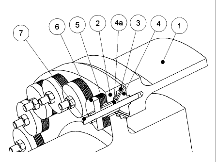
The invention thus relates to an elastic machine or gearbox bearing for the
transmis-
1o sion of the forces and moments occurring in all spatial directions, in
particular axially
and radially, and for the reduction or isolation of vibrations occurring,
which compri-
ses an axially oriented elastomeric sandwich element (5) and an elastomeric
cone
element (3), which is installed above or below the former and whose axis is
oriented
perpendicular to the sandwich element (5) and whose tapered end is positioned
against this sandwich element (5), where the elements (3) and (5) are
connected to
one another by a cone piece (4), which is surrounded centrally by the cone
element
(3), and a cylinder piece (4a), which is surrounded centrally by the sandwich
element
(5), and each of the elements (3), (5), (4), (4a) has a central axially
oriented hole for
the accommodation of a clamping bolt or a clamping screw (7) for clamping a
mach-
ine part (2), which is introduced between the elastomeric elements (3) and (5)
and
generally functions as clamping flange, to the machine part (1), which is
installed
below the element (3) and functions as attachment flange.
In accordance with the invention, the elastic force-transmission moment now
consists
of an elastic cone element (3) and an elastic sandwich element (5), which is
axially
clamped thereto. Whereas the cone element (3) transmits axial forces and
radial
forces, the sandwich element (5) transmits virtually exclusively axial forces.
The
resultant total force acting on the bearing according to the invention now
acts in the
region of the cone piece (4) with a widened cross section, so that the bending
mom-
ent formed no longer acts on the narrow connecting piece (4a) or the clamping
means (7) to this extent and no longer results in a loosening of the
attachment or in
material fatigue.
CA 02743228 2011-05-10
WO 2010/054808 PCT/EP2009/008044
- 3 -
The stiffness of the sandwich element (5) is, in accordance with the
invention,
approximately a factor of 2 - 100, preferably 10 - 100, in particular 50 -
100, smaller
than the radial stiffness of the cone element (3).
The radial force transmission in the bearing also takes place in accordance
with the
radial stiffness ratio. Thus, about 2 - 100 times as much radial force is
transmitted in
the cone element (3) as in the sandwich element (5). The radial force
transmission in
(5) is thus negligible. This has the consequence that a large bending moment
does
not have to be transmitted in the cone piece (4), which results in alleviation
of the
load on the cylinder piece (4a), which is adjacent to the cone piece (4) and
through
io which the clamping means (7) is also passed, so that this and also the
clamping
means merely have to be dimensioned for the tensile and compression forces
arising.
The introduction of load from the cone piece (4) into the attachment flange
(1) is also
simplified by the fact that virtually pure shear has to be transmitted here
and the
bending moment is significantly smaller than in the prior-art design in
accordance with
Figure 1. In an embodiment of the invention, cone piece (4) and attachment
flange (1)
can also be integral constituents of a single component.
In principle, the cone piece (4) and the cylinder piece (4a) can also be a
single work-
piece.
The two elements are thus clamped to one another in the axial direction. The
two
elements may have the same stiffness in the axial direction, but this is not
absolutely
necessary. However, the cone element (3) has significantly greater stiffness
in the
radial direction than the sandwich element (5).
The pre-tensioning and axial force transmission in the case of the sandwich
element
preferably take place via a pressure plate (6), which is provided with a hole
which is
able to accommodate the clamping bolt or the clamping screw (7).
The invention thus relates to a corresponding bearing which has a pressure
plate
which is in direct or indirect contact with the sandwich element (5).
CA 02743228 2011-05-10
WO 2010/054808 PCT/EP2009/008044
4 -
In a particular embodiment, the pressure plate (6) and the sandwich element
(5) form
a constructional unit.
It has furthermore been found that the force distribution over the entire
bearing ele-
ment is particularly advantageous if the fixed, non-elastic, conical cone
piece (4) is
not formed by a simple cone surface, but instead has convex curvature. The
effect
can be reinforced further if the elastomeric cone element (3) furthermore also
has
corresponding concave curvature on the inside and preferably also on the
outside, so
that its inside surface can come to rest on the outside surface of the cone
piece (4)
with an accurate fit.
io In a further embodiment, the cone piece (4) with the cylinder piece (4a)
can form a
constructional unit.
The invention thus relates to a corresponding bearing in which the cone piece
(4) has
a surface with convex curvature on which the inside surface of the cone
element (3)
lies. In a further embodiment, the components (3) and (4) may again in
accordance
is with the invention be combined to form a single constructional unit.
The invention also relates to a corresponding bearing in which the inside
surface of
the cone element (3) has concave curvature, and preferably also in addition
the out-
side surface of the cone element (3) has concave curvature.
The elastomer elements (3) and (5) have 1 or more elastomer layers. In
general, they
20 essentially consist of at least two elastomer layers, which are separated
by a stiff
interlayer, usually a metal plate. The elements preferably consist of three to
five elas-
tomeric layers with corresponding intermediate plates or interlayers. The
elements
are terminated on the outside by likewise stiff layers/plates.
The elastomer materials used for the bearings according to the invention
essentially
25 consist of a natural rubber, a natural rubber derivative or of a suitable
elastic poly-
meric plastic or plastic mixture. In accordance with the invention, the
elastomer layer
may have different hardness ("Shore hardness") and different damping
properties,
corresponding to the desired requirements. Elastomers having a hardness of 20
to
100 Shore A, in particular 30 to 80 Shore A, are preferably used. The
preparation of
CA 02743228 2011-05-10
WO 2010/054808 PCT/EP2009/008044
-
such elastomers of different hardness is known from the prior art and is
adequately
described in the relevant literature.
In accordance with the invention, the stiff intermediate plates or interlayers
are made
from materials having high stiffness, high strength and low compressibility.
These are
5 preferably metal sheets, but other materials, such as hard plastics,
composite materi-
als or carbon fiber-containing materials, can also be employed. The
intermediate
metal sheets and the elastomer materials are generally connected to one
another
during vulcanization.
The cone element (3) of the bearing according to the invention should have a
cone
1o angle of 10 - 50 with respect to machine axis (a) or to the axis of the
clamping ele-
ment (7) against or in the screw-in direction. It preferably has a cone angle
of 25 -
50 .
The bearing according to the invention is versatile and can be employed in
different
ways. As a so-called unilateral bearing arrangement, it is particularly
suitable for wind
turbines in order to produce, in particular, a rotational elastic connection
between the
rotor shaft, the gearbox or a rotor/gearbox unit and the bedplate.
However, it can also be employed in couplings as described in EP 1 593 867 B1
instead of the elastomer bearings mentioned therein.
The bearing according to the invention can also be employed as tower
decoupling in
wind turbines, as described in EP 1 065 374 B1, which additionally results in
simplifi-
cation.
It is likewise possible to improve machine feet in accordance with EP 1 065
374 B1 in
that the bending moment between the flanges having the design described can be
reduced and the screw forces can thus be decreased.
CA 02743228 2011-05-10
WO 2010/054808 PCT/EP2009/008044
6 -
Description of the reference numerals in the drawings
1 Attachment flange
2 Clamping flange
3 Elastomeric cone element
4 Cone piece
4a Cylinder piece
5 Elastomeric sandwich element
6 Pressure plate
7 Clamping means (screw/bolt)
8 Cone piece clamping side
9 Cone piece supported unilaterally
10 Symmetrical elastomeric cone bearing
11 Separation between the cones
Description of the drawings
Figure 1 Conventional elements arranged in a circular manner
Figure 2 Circular arrangement of the elements in accordance with the invention
Figure 3 Section through a bearing in accordance with the invention