Note: Descriptions are shown in the official language in which they were submitted.
CA 02743546 2011-05-11
A method and a device for the analysis of Code.Domain Power
and Code Domain Error Power
The invention relates to a method and a device for the
analysis of Code Domain Power (CDP) and Code Domain Error
Power (CDEP).
US 7,162,396 B2 discloses a device for the display of Code
Domain Power (CDP) measured results. The device displays the
measured results in the form of bars in a diagram. The diagram
provides a horizontal axis and a vertical axis, wherein code
channels and spreading factors are plotted on the horizontal
axis, and a measurement for the power is plotted on the
vertical axis. The height of a bar indicates the power of a
code channel. By contrast, its position on the horizontal axis
indicates the code channel and the spreading factor. As an
alternative to the power of an active code channel, the noise
of an inactive code channel can also be displayed in the
diagram. However, a Code Domain Error Power (CDEP) is not
displayed. Accordingly, the error with which an active code
channel is affected is not evident. In particular, the ratio
in which the error stands to the power is not evident. In
particular, it is not possible to compare the error with the
power.
The invention is therefore based on the object of providing a
method and a device, with which a comparison of Code Domain
Power (CDP) and Code Domain Error Power (CDEP) of a channel is
possible.
1
CA 02743546 2011-05-11
This object is achieved by the method according to the
invention specified in claim 1 and by the device according to
the invention specified in claim 8.
The method according to the invention for the analysis of Code
Domain Power (CDP) and Code Domain Error Power (CDEP) of
different code channels comprises a reception of at least one
signal, an evaluation of the signal, a determination of at
least one Code Domain Power (CDP) of at least one code
channel, a determination of at least one Code Domain Error
Power (CDEP) of the code channel and simultaneous display of
the Code Domain Power (CDP) and the Code Domain Error Power
(CDEP) of at least one channel.
For this purpose, the device according to the invention for
the simultaneous display of Code Domain Power (CDP) and Code
Domain Error Power (CDEP) of different code channels comprises
a device for the reception of a signal, a device for the
evaluation of the signal, a device for determining a Code
Domain Power (CDP) of a code channel, a device for determining
a Code Domain Error Power (CDEP) of the code channel and a
device for the simultaneous display of the Code Domain Power
(CDP) and the Code Domain Error Power (CDEP).
A signal to be measured, for example, a CDMA signal of a base
station, is received by the device for the reception of a
signal and measured by the device for the measurement of the
signal. The measurement is evaluated by the device for the
evaluation of the signal. From the evaluation of the signal, a
Code Domain Power (CDP) of a code channel is determined by
means of the device for determining a Code Domain Power (CDP)
2
CA 02743546 2011-05-11
of a code channel. For this code channel, a Code Domain Error
power (CDEP) of the code channel is determined by means of the
device for determining a Code Domain Error Power (CDEP). The
determined Code Domain Power (CDP) and the determined Code
Domain Error Power (CDEP) are displayed simultaneously by
means of the device for the simultaneous display of the Code
Domain Power (CDP) and the Code Domain Error Power (CDEP).
The simultaneous display allows a simple overview of the
relationships between Code Domain Power (CDP) and Code Domain
Error Power (CDEP) of a code channel. A comparison of both
values is accordingly made possible and facilitated. The type
of display can be selected from various types. For example,
different scales and/or colours etc. can be selected and
matched to a user or application.
The dependent claims present advantageous embodiments of the
method according to the invention and respectively the device
according to the invention.
By preference the Code Domain Power (CDP) and the Code Domain
Error Power (CDEP) are each determined from the same time slot
of the evaluated signal. Accordingly, the determined Code
Domain Power (CDP) and the determined Code Domain Error Power
(CDEP) are actually associated with one another and derived
from the same data basis. Moreover, it is possible in this
manner to update the actually associated data at a faster
rate. For this purpose, the device for determining the Code
Domain Power (CDP) and the device for determining the Code
Domain Error Power (CDEP) are preferably set up in such a
manner that the Code Domain Power (CDP) and the Code Domain
3
CA 02743546 2011-05-11
Error Power (CDEP) can each be determined from the same time
slot of the evaluated signal.
By preference, the Code Domain Error Power (CDEP) is
determined on the basis of one of several respectively
selectable algorithms (for example, directly by a user and/or
indirectly through a program by means of a device for the
selection of an algorithm). These can be stored in a buffer
and loaded as required. The selection takes place, for
example, through a user entry on the basis of which the
algorithm is loaded. In this context, the selection is
especially independent of the determination of the algorithm
for determining the Code Domain Power.
In this manner, it is possible to select the algorithm and
adapt it to an application and/or a specific user interest.
For this purpose, the device for determining the Code Domain
Error Power (CDEP) is set up in such a manner that the Code
Domain Error Power (CDEP) can be determined on the basis of
one of several respectively selectable algorithms. By
preference, the device for the simultaneous display of Code
Domain Power (CDP) and Code Domain Error Power (CDEP) also
comprises for this purpose a device for selecting the
algorithm.
By preference, the Code Domain Power (CDP) and the Code Domain
Error Power (CDEP) are displayed in a diagram with a
horizontal x-axis and a vertical y-axis, the Code Domain Power
(CDP) is displayed by a first bar in the positive y-direction
with a first scale, the Code Domain Error Power (CDEP) is
displayed by a second bar in the negative y-direction with a
4
CA 02743546 2011-05-11
second scale, and the first bar and the second bar are placed
opposite one another. Accordingly, a simple and logically
arranged, simultaneous display of actually associated data
(CDP & CDEP) is made possible. For this purpose, the device
for the simultaneous display of the Code Domain Power (CDP)
and the Code Domain Error Power (CDEP) is preferably set up in
such a manner that the Code Domain Power (CDP) and the Code
Domain Error Power (CDEP) can be displayed in a diagram with a
horizontal x-axis and a vertical y-axis, the Code Domain Power
(CDP) can be displayed by a first bar in the positive y-
direGtion with a first scale, the Code Domain Error Power
(CDEP) can be displayed by a second bar in the negative y-
direction with a second scale, and the first bar and the
second bar can be placed opposite to one another.
By preference, the first scale and/or the second scale are
adjusted individually, that is to say, independently of one
another. Through this adjustability, the scales and the size
of the display of the individual data (CDP & CDEP) can be
adjusted in a user-defined manner. Accordingly, the display
can be enlarged if a user wants to identify a precise value
more accurately, and reduced, if a user does not want the
precise value to dominate the overall display. For this
purpose, the device for simultaneous display of Code Domain
Power (CDP) and Code Domain Error Power (CDEP) of different
code channels is preferably set up in such a manner that the
first scale and/or the second scale can be adjusted
independently of one another.
By preference, a Code Domain Power (CDP) of an I-branch and/or
a Code Domain Power (CDP) of a Q-branch is determined as the
CA 02743546 2011-05-11
Code Domain Power (CDP). In this manner, a more detailed
display of the power structure of a total signal which is
subdivided into signal components, is possible.
For this purpose, the device for determining the Code Domain
Power (CDP) is set up in such a manner that a Code Domain
Power (CDP) of an I-branch is determinable as the Code Domain
Power (CDP). The device for determining the Code Domain Error
Power (CDEP) is set up in such a manner that a Code Domain
Power (CDP) of a Q-branch is determinable as the Code Domain
Power (CDP).
A preferred exemplary embodiment of the method according to
the invention for the simultaneous display of Code Domain
Power (CDP) and Code Domain Error Power (CDEP) is shown in the
drawings and explained in greater detail in the subsequent
description. The drawings are as follows:
Figure 1 shows a flow chart of the method according to the
invention for the analysis of Code Domain Power
(CDP) and Code Domain Error Power (CDEP);
Figure 2 shows a block-circuit diagram of the device
according to the invention for the analysis and
simultaneous display of Code Domain Power (CDP) and
Code Domain Error Power (CDEP);
Figure 3 shows the structure of a second determination
device for determining a Code Domain Power (CDP) of
a code channel;
6
CA 02743546 2011-05-11
Figure 4 shows a preferred display of Code Domain Power
(CDP) and Code Domain Error Power (CDEP) by means
of the method according to the invention and
respectively by means of the device according to
the invention.
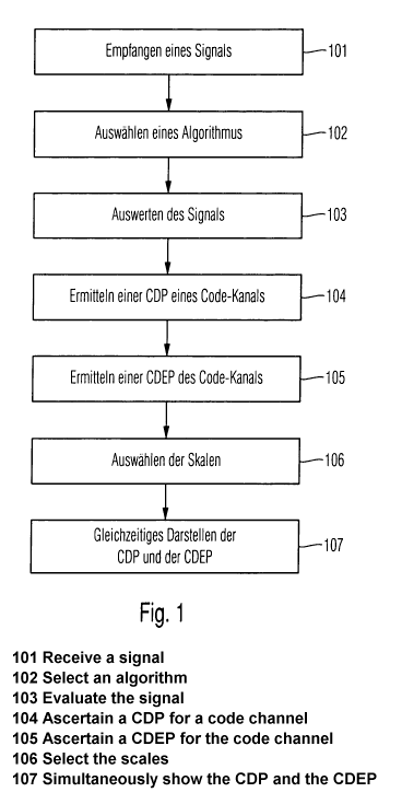
Figure 1 and Figure 2 show a flow chart of an exemplary
embodiment of the method according to the invention and
respectively a block-circuit diagram of an exemplary
embodiment of the device according to the invention.
The method according to the invention for the simultaneous
display of Code Domain Power (CDP) and Code Domain Error Power
(CDEP) of different code channels comprises several steps 101
- 107. The device 200 according to the invention for the
simultaneous display of Code Domain Power (CDP) and Code
Domain Error Power (CDEP) of different code channels comprises
for this purpose several devices for the implementation of the
steps 101 - 107. The device 200 according to the invention for
the analysis and simultaneous display of Code Domain Power
(CDP) and Code Domain Error Power (CDEP) comprises a reception
device 201 for a reception (measurement/sampling in the time
domain), mixing down from the high frequency range and low-
pass filtering of a CDMA signal of a base station 210. The
signal processed in this manner is buffered in a buffer 208.
Furthermore, the measuring device 200 contains a first
determination device 202 for determining an algorithm with
which the further evaluation is to be implemented, an
evaluation device 203 for the evaluation of the signal with
the algorithm determined, a second determination device 204
for determining the Code Domain Power (CDP) of a code channel,
7
CA 02743546 2011-05-11
a third determination device 205 for determining a Code Domain
Error Power (CDEP) of the code channel (preferably
simultaneously during the determination of the CDP or after
the determination of the CDP), a fourth determination device
206 for determining a scale, and a display device 207 for the
simultaneous display of the Code Domain Power (CDP) and the
Code Domain Error Power (CDEP). The first determination device
202 and the fourth determination device 206 are contained in a
control device 226. The evaluation device 203, the second
determination device 204 and the third determination device
205 are contained in a control device 209, which can be
operated by a user for the control of the device 200 according
to the invention.
The buffer 208 is connected to all of the devices 201-207 of
the devices 200 according to the invention for a data
exchange. Moreover, the first determination device 202 and the
second determination device 204, and also the first
determination device 202 and the third determination device
205, and also the fourth determination device 206 and the
display device 207, and also the evaluation device 203 and the
second determination device 204, and also the second
determination device 204 and the third determination device
205 are connected to one another in each case for a data or
information exchange. The buffer 208 buffers both measured
results and also the data which are generated and/or processed
by the devices which are connected to the buffer 208. In
particular, the buffer 208 buffers the selectable algorithms
and the software for the control of the display device 207.
8
CA 02743546 2011-05-11
The device according to the invention comprises, for
communication with a user, a display (207) or screen (207) and
an input port, for example, for a keyboard, a mouse and/or
keys and rotary knobs on a front panel of the device 200
according to the invention, which are connected to the control
device 226.
The method begins with the reception 101 of at least one
signal, preferably a CDMA signal of a base station 210, by
means of the reception device 201 for the reception of the
signal. For the evaluation of the signal, an algorithm is
determined 102 by means of a first determination device 202;
for example, through selection from a set of algorithms, which
are stored in the buffer 208. The signal is evaluated 103 in
an evaluation device 203 for the evaluation of the signal.
From the evaluated signal, at least one Code Domain Power
(CDP) of the code channel is determined 104 by means of a
second determination device 204 for determining a Code Domain
Power (CDP) of a code channel. The CDP measurement analyses
the power distribution via the individual code channels.
Moreover, a Code Domain Error Power (CDEP) of the code channel
is determined 105 from the evaluated signal by means of a
third determination device 205, preferably by means of the
determined algorithm. The CDEP is an analysis of the error
signal in the code range, that is to say, the projection of
the error power onto the individual code channels. For the
formation of the display of the Code Domain Power (CDP) and of
the Code Domain Error Power (CDEP), scales for the display are
preferably determined 106, for example, through selection by
means of a fourth determination device for the determination
and respectively selection of scales 206. This can be
9
CA 02743546 2011-05-11
implemented automatically by a program and/or in an active
manner by a user. The determined Code Domain Power (CDP) and
the determined Code Domain Error Power (CDEP) are displayed
simultaneously 107 by means of a display device 207 for the
simultaneous display of the Code Domain Power (CDP) and the
Code Domain Error Power (CDEP).
The simultaneous display 107 makes possible and facilitates
the overview of the value ratios between Code Domain Power
(CDP) and Code Domain Error Power (CDEP) of a code channel.
The method of display is selected between various options. For
example, special scales and/or colours and/or fields and/or
edges of fields and/or bar widths are selected. The display is
adapted, for example, to a given application, either
automatically and dependent upon the Code Domain Power (CDP)
and/or upon the Code Domain Error Power (CDEP), or selected
actively by a user.
In one exemplary embodiment, the Code Domain Power (CDP) and
the Code Domain Error Power (CDEP) are determined 104, 105
respectively from the same time slot of the evaluated signal.
This ensures that the determined Code Domain Power (CDP) and
the determined Code Domain Error Power (CDEP) are actually
associated with one another, that is to say, are derived from
the same data basis. Since both values can be determined from
one time interval, it is not necessary to use two time
intervals, which would either lead to an unnecessarily long
time interval or to an excessively small sampling value of the
measured values in order to determine values of CDP and CDEP
which would then not actually be associated with one another.
In this manner, it is possible to update the actually
CA 02743546 2011-05-11
associated data at a faster rate with an acceptable sampling
size of the measured values.
The second determination device 204 for determining the Code
Domain Power (CDP) and the third determination device 205 for
determining the Code Domain Error Power (CDEP) are designed
for this purpose in such a manner that the Code Domain Power
(CDP) and the Code Domain Error Power (CDEP) are each
determinable on the basis of measured values of a single time
interval or respectively time slot of the evaluated signal.
For this purpose, the devices 204 and 205 use common data from
an evaluation device 203 for the evaluation of the signal.
The Code Domain Error Power (CDEP) is preferably determined on
the basis of an algorithm, which can be selected 105 from a
set of several respectively selectable algorithms. The device
for the simultaneous display of Code Domain Power (CDP) and
Code Domain Error Power (CDEP) preferably comprises for this
purpose a first selection device 202 for the selection of the
algorithm. A user selects the algorithm directly or indirectly
from an assortment of possible algorithms. For the direct
selection, the user indicates which type of Code Domain Error
Power (CDEP) is to be determined.
The type of display of Code Domain Power (CDP) and Code Domain
Error Power (CDEP) is also selected automatically or by a
user. By preference, the Code Domain Power (CDP) and the Code
Domain Error Power (CDEP) are displayed in an x-y diagram with
horizontal x-axis and vertical y-axis. The Code Domain Power
(CDP) is displayed by a first bar of a first colour in the
positive y-direction with a first scale. Similarly, the Code
11
CA 02743546 2011-05-11
Domain Error Power (CDEP) is preferably displayed by a second
bar of a second colour in the negative y-direction with a
second scale. The first bar and the second bar are preferably
disposed opposite one another. By preference, the first scale
and/or the second scale are adjusted independently of one
another. The width of the bars, the first colour and a second
colour are also selectable in each case. Instead of being
disposed opposite one another, the bars can optionally, that
is to say, also in a selectable manner, be disposed side-by-
side. Instead of bars, simple lines can be selected and used.
In each case, the selection actions are preferably implemented
respectively through or by means of the fourth selection
device 206 for the selection of the scales. A simple and
logically arranged simultaneous display of actually associated
data (CDP & CDEP) is then made possible in principle and also
capable of flexible modification, for example, by a user. The
modifiable display described is implemented 107 by means of
the display device 207 for the simultaneous display of the
Code Domain Power (CDP) and the Code Domain Error Power
(CDEP).
A Code Domain Power (CDP) of an I-branch and/or a Code Domain
Power (CDP) of a Q-branch is preferably determined as the Code
Domain Power (CDP). A Code Domain Error Power (CDEP) is
determined respectively for every Code Domain Power (CDP),
whether it is from the I-branch or from the Q-branch. For
every CDP, a CDEP corresponding to it, that is, associated
with it, is determined. These associated CDP and CDEP can each
be displayed as described above. In this manner, a complete
display of the power structure (distribution of the total
power between the individual channels and branches) of a total
12
CA 02743546 2011-05-11
signal, which is subdivided into signal components (channels
and branches), is possible. The second determination device
204 for determining the Code Domain Power (CDP) is set up in
such a manner that a Code Domain Power (CDP) of an I-branch
and/or of an Q-branch is determinable as the Code Domain Power
(CDP).
Figure 3 shows how the second determination device 204
determines 104 a Code Domain Power (CDP) of a code channel.
The second determination device 204 comprises an I/Q
demodulator 41, a first filter 42, a second filter 42', a
first processor 43, a second processor 43', a first CDP
calculator 44 and a second CDP calculator 44'. The IN
demodulator 41 splits the signal into an I signal, which is
rerouted to the first filter 42, and a Q-signal, which is
rerouted to the second filter 42'. In each case, the first
filter 42 and the second filter 42' reroute amplitude
information and phase information from the received signals to
the first processor 43 and respectively to the second
processor 43'. The first processor 43 and the second processor
43' decode and despread the received signals and reroute the
results to the first CDP calculator 44 or respectively to the
second CDP calculator 44'. The first CDP calculator 44 and the
second CDP calculator 44' calculate the Code Domain Power
(CDP) of the I-signal (I-branch) or of the Q-signal (Q-
branch).
Figure 4 shows a display of CDP values and CDEP values in the
form of bars in bar diagrams, which are determinable by means
of the described exemplary embodiment of the method according
to the invention, which can be implemented by means of the
13
CA 02743546 2011-05-11
described exemplary embodiment of the device according to the
invention.
In a first diagram 1, a horizontal, first x-axis 3 and a
vertical, first y-axis 4 are illustrated. Code channels are
arranged on the horizontal first x-axis 3. The vertical first
y-axis is subdivided into a first portion 5 and a second
portion 6. The first portion 5 provides the first scale for
the display of CDP values. The second portion 6 provides the
scale for the display of CDEP values. In each case, a CDP and
an associated CDEP for a first active code channel.78 and also
for a first inactive code channel 910 are displayed in the
first diagram 1. The first active code channel 78 provides a
first CDP in the form of a first bar 7 and a first CDEP in the
form of a second bar 8. The first inactive code channel 910
provides a second CDP in'the form of a third bar 9 and a
second.CDEP in the form of a fourth bar 10. The first active
code channel 78 is contained within a group of active code
channels a.
Instead of a display of the individual powers of the channels
of the group of active code channels a, which are allocated,
for example, in each case to a common superordinate code
channel of relatively lower spreading factor, a total power
for the group of active code channels a can be displayed in
the form of a single bar. For this total power for the group
of active code channels a, an associated CDEP can also be
determined (for example, by summation of the individual CDPs)
and displayed in the form of a further single bar. The total
power for the group of active code channels a is determined in
a similar manner for the power of a single code channel. The
14
CA 02743546 2011-05-11
method described and the device described can accordingly be
used in a similar manner for the total power CDP((x) and a CDEP
(CDP((x)) associated with it, or respectively for their
determination and display.
In a similar manner, a horizontal second x-axis 11 and a
vertical second y-axis 12 are shown in a second diagram 2. The
horizontal second x-axis 3 images code channels, while the
vertical second y-axis is subdivided into a third portion 13
and a fourth portion 14, wherein the third portion 13 provides
a third scale for the display of CDP values, and the fourth
portion 14 provides a fourth scale for the display of CDEP
values. In the second diagram 2, a CDP and also a CDEP
allocated to the CDP are displayed for a second active code
channel 1516 and also for a second inactive channel 1718 in
each case, wherein the second active code channel 1516
provides a third CDP in the form of a fifth bar 15 and a third
CDEP in the form of a sixth bar 16, and the second inactive
code channel 1718 provides a fourth CDP in the form of a
seventh bar 17 and a fourth CDEP in the form of the eighth bar
18.
The first diagram 1 and the second diagram 2 relate to the
same code channels. In the first diagram 1, the CDP values and
CDEP values associated with their I-branches are displayed for
the code channels. By contrast, in the second diagram 2, the
CDP values and the CDEP values associated with their Q-
branches are shown for the code channels. In both diagrams 1,
2, each CDP is disposed opposite to its associated CDEP.
CA 02743546 2011-05-11
By preference, the value -128dB is allocated to the zero point
of the y-axis, while the first portion 5, the second portion
6, the first portion 13 and the fourth portion 14 extend
outwards from this zero point up to OdB. By preference, a
common scale is used for both y-axis directions in both
diagrams 1, 2 respectively. Alternatively, other negative
values can be allocated to the zero point. The length of the
portions (5, 6, 13, 14) is variable.
Figure 4 shows how the second determination device 204
determines 104 a Code Domain Power (CDP). The second
determination device 204 comprises an I/Q-demodulator 41, a
first filter 42, a second filter 42', a first processor 43, a
second processor 43', a first CDP calculator 44 and a second
CDP calculator 44'. The I/Q-demodulator 41 splits the signal
into an I-signal, which is rerouted to the first filter 42,
and a Q-signal, which is rerouted to the second filter 42'.
The first filter 42 and the second filter 42' reroute
amplitude information and phase information from the
respectively received signals in each case to the first
processor 43 or to the second processor 43'. The first
processor 43 and the second processor 43' decode and despread
the received signals respectively and reroute the results to
the first CDP calculator 44 or to the second CDP calculator
44'. The first CDP calculator 44 and the second CDP calculator
44' calculate the Code Domain Power (CDP) of the I-signal (I-
branch) and respectively of the Q-signal (Q-branch). The
inactive channels provide a noise power, which leads to the
displayed bars.
16
CA 02743546 2011-05-11
The invention is not restricted to the exemplary embodiments
displayed. On the contrary, individual features of the
exemplary embodiments can also be advantageously combined with
one another.
17