Note: Descriptions are shown in the official language in which they were submitted.
CA 02743900 2016-05-17
30253-30
SEALANT-FILLED ENCLOSURES AND METHODS FOR ENVIRONMENTALLY
PROTECTING A CONNECTION
Related Application(s)
10011 The present application claims the benefit of and priority from U.S.
= Provisional Patent Application Serial No. 61/115,746, filed November 18,
2008.
Field of the Invention
[002] The present invention relates to environmentally protective enclosures
and,
, more
particularly, to enclosures for environmentally protecting cable connections
and the like.
Background of the Invention
[0031 Sealant-filled environmentally protective enclosures are employed to
protect
, cable connections. Such enclosures may be used to environmentally protect
the connections
between telecommunications signal transmission cables, the electrical power
transmission
cables, etc. For example, U.S. Patent No. 5,763,835 to Huynh-Ba et al.
discloses a gel-filled
enclosure including a pair of cavitied bodies that are hingedly connected and
closable in clam
shell fashion. When the enclosure is closed about the cables, gel is typically
displaced and
thereby elongated and seals about a cable splice or the like.
[0041 However, such enclosures are typically adapted to suitably seal about a
limited
range of connection/cable sizes. Additionally, for relatively large
connections and cables, the
force required to close an enclosure about the connection/cables may be unduly
large.
However, such enclosures are typically adapted to suitably seal about a
limited range of
connection/cable sizes. Additionally, for relatively large connections and
cables, the force
required to close an enclosure about the connection/cables may be unduly
large. In general,
for larger enclosures and cable/connector volumes, there may be large
difference in volume
' from the minimum to the maximum intended cable/connector configurations. As
a result, it
1
CA 02743900 2016-05-17
30253-30
may be difficult to provide an amount of gel in the enclosure sufficient to
properly seal the
smallest intended configuration but which will still allow the operator to
easily close the
enclosure. When a large volume of gel must be displaced to accommodate a large
cable/connector, the gel may extrude through an end of the enclosure or even
climb over side
walls (in which case, the gel may accumulate at a latch area). These actions
may generate
substantial internal pressure in the enclosure that makes the enclosure
difficult to close.
Summary of the Invention
[005] According to embodiments of the present invention, a sealant-filled
enclosure assembly for environmentally protecting a connection includes a
housing, a mass of
sealant and a sealant valve mechanism. The housing includes a main cavity to
receive the
connection. The mass of sealant is disposed in the main cavity. The sealant
valve mechanism
includes an overflow chamber and a gate member between the main cavity and the
overflow
chamber. The gate member is selectively positionable in each of a closed
position, wherein
the gate member substantially prevents displacement of the sealant from the
main cavity to the
overflow chamber, and an open position, wherein the gate member permits
displacement of
the sealant from the main cavity to the overflow chamber.
[006] According to method embodiments of the present invention, a method
for environmentally protecting a connection includes providing a sealant-
filled enclosure
assembly. The sealant-filled enclosure assembly includes a housing, a mass of
sealant and a
sealant valve mechanism. The housing includes a main cavity to receive the
connection. The
mass of sealant is disposed in the main cavity. The sealant valve mechanism
includes an
overflow chamber and a gate member between the main cavity and the overflow
chamber.
The gate member is selectively positionable in each of a closed position,
wherein the gate
member substantially prevents displacement of the sealant from the main cavity
to the
overflow chamber, and an open position, wherein the gate member permits
displacement of
the sealant from the main cavity to the overflow chamber. The method further
includes:
placing the connection in the main cavity; transitioning the gate member from
the closed
position to the open position; and displacing a portion of the sealant from
the main cavity to
the overflow chamber.
2
CA 02743900 2016-05-17
30253-30
[006a] According to one aspect of the present invention, there is provided a
sealant-filled enclosure assembly for environmentally protecting a connection
including a pair
of cables and a connector joining the cables, the sealant-filled enclosure
assembly comprising:
a housing including a main cavity to receive the connection and at least one
cable port to
receive the cables extending from the connection; a mass of sealant disposed
in the main
cavity; and a sealant valve mechanism including: an overflow chamber; a valve
port
connecting the main cavity to the overflow chamber; and a gate member between
the main
cavity and the overflow chamber; wherein the gate member is selectively
positionable in each
of a closed position, wherein the gate member spans the valve port and
substantially prevents
displacement of the sealant from the main cavity to the overflow chamber
through the valve
port, and an open position, wherein the gate member permits displacement of
the sealant from
the main cavity to the overflow chamber through the valve port; and wherein,
when the
connection is mounted in the housing, the cables extend through the at least
one cable port and
do not extend through the valve port.
[006E11 According to another aspect of the present invention, there is
provided
a method for environmentally protecting a connection including a pair of
cables and a
connector joining the cables, the method comprising: providing a sealant-
filled enclosure
assembly including: a housing including a main cavity to receive the
connection and at least
one cable port to receive the cables extending from the connection; a mass of
sealant disposed
in the main cavity; and a sealant valve mechanism including: an overflow
chamber; a valve
port connecting the main cavity to the overflow chamber; and a gate member
between the
main cavity and the overflow chamber; wherein the gate member is selectively
positionable in
each of a closed position, wherein the gate member spans the valve port and
substantially
prevents displacement of the sealant from the main cavity to the overflow
chamber, and an
open position, wherein the gate member permits displacement of the sealant
from the main
cavity to the overflow chamber through the valve port; placing the connection
in the main
cavity such that the cables extend through the at least one cable port and do
not extend
through the valve port; transitioning the gate member from the closed position
to the open
position; and displacing a portion of the sealant from the main cavity to the
overflow chamber
through the valve port, wherein the cables do not extend through the valve
port.
2a
CA 2743900 2017-05-15
30253-30
[006c] According to still another aspect of the present invention, there is
provided a connection assembly comprising: a connection including a pair of
cables and a
connector joining the cables; a sealant-filled enclosure assembly for
environmentally
protecting the connection, the sealant-filled enclosure assembly comprising: a
housing
including a main cavity to receive the connection and at least one cable port
to receive the
cables extending from the connection; a mass of sealant disposed in the main
cavity; and a
sealant valve mechanism including: an overflow chamber; a valve port
connecting the main
cavity to the overflow chamber; and a gate member between the main cavity and
the overflow
chamber; wherein the gate member is selectively positionable in each of a
closed position,
wherein the gate member spans the valve port and substantially prevents
displacement of the
sealant from the main cavity to the overflow chamber through the valve port,
and an open
position, wherein the gate member permits displacement of the sealant from the
main cavity to
the overflow chamber through the valve port; and the connection is mounted in
the housing
such that the cables extend through the at least one cable port and do not
extend through the
valve port.
[007] Further features, advantages and details of the present invention will
be
appreciated by those of ordinary skill in the art from a reading of the
figures and the detailed
2b
CA 02743900 2011-05-16
WO 2010/059619 PCT/US2009/064778
description of the embodiments that follow, such description being merely
illustrative of the
present invention.
Brief Description of the Drawings
[008] Figure 1 is a top perspective view of a sealant-filled enclosure
assembly
according to embodiments of the present invention in an open position and with
a connection
partially installed therein.
[009] Figure 2 is a top perspective view of a housing forming a part of the
sealant-
filled enclosure assembly of Figure 1 in an open position.
[0010] Figure 3 is a cross-sectional view of the housing of Figure 2 taken
along the
line 3-3 of Figure 2.
[0011] Figure 4 is a cross-sectional view of the housing of Figure 2 taken
along the
line 4-4 of Figure 2.
[0012] Figure 5 is a cross-sectional view of the housing of Figure 2 taken
along the
line 5-5 of Figure 2.
[0013] Figure 6 is a top perspective view of the sealant-filled enclosure
assembly of
Figure 1 installed about the connection to form a connection assembly.
[0014] Figure 7 is a cross-sectional view of the connection assembly of Figure
6
taken along the line 7-7 of Figure 6, wherein the gate members of the sealant-
filled enclosure
assembly are in their closed positions.
[0015] Figure 8 is a cross-sectional view of the connection assembly of Figure
6
taken along the line 8-8 of Figure 7, wherein the gate members of the sealant-
filled enclosure
assembly are in their closed positions.
100161 Figure 9 is a cross-sectional view of the connection assembly of Figure
6
taken along the line 9-9 of Figure 7, wherein the gate members of the sealant-
filled enclosure
assembly are in their closed positions.
[0017] Figure 10 is a cross-sectional view of the connection assembly of
Figure 6
taken along the line 7-7 of Figure 6, wherein the gate members of the sealant-
filled enclosure
assembly are in their open positions.
[0018] Figure 11 is atop perspective view of a sealant-filled enclosure
assembly
according to further embodiments of the present invention in an open position.
100191 Figure 12 is atop perspective view of a cover member of a housing
forming a
part of the sealant-filled enclosure assembly of Figure 11 in an open
position.
3
CA 02743900 2011-05-16
WO 2010/059619 PCT/US2009/064778
[0020] Figure 13 is a bottom perspective view of the cover member of Figure
12.
[0021] Figure 14 is a cross-sectional view of the cover member of Figure 12
taken
along the line 14-14 of Figure 12.
[0022] Figure 15 is a longitudinal, center cross-sectional view of the sealant-
filled
enclosure assembly of Figure 11 installed on a connection to form a connection
assembly,
wherein the gate members thereof are in their open positions and supplemental
stop members
of the sealant-filled enclosure assembly are in their deployed positions.
Detailed Description of Embodiments of the Invention
[0023] The present invention now will be described more fully hereinafter with
reference to the accompanying drawings, in which illustrative embodiments of
the invention
are shown. In the drawings, the relative sizes of regions or features may be
exaggerated for
clarity. This invention may, however, be embodied in many different forms and
should not
be construed as limited to the embodiments set forth herein; rather, these
embodiments are
provided so that this disclosure will he thorough and complete, and will fully
convey the
scope of the invention to those skilled in the art.
[0024] It will be understood that, although the terms first, second, etc. may
be used
herein to describe various elements, components, regions, layers and/or
sections, these
elements, components, regions, layers and/or sections should not be limited by
these terms.
These terms are only used to distinguish one element, component, region, layer
or section
from another region, layer or section. Thus, a first element, component,
region, layer or
section discussed below could be termed a second element, component, region,
layer or
section without departing from the teachings of the present invention.
[0025] Spatially relative terms, such as "beneath", "below", "lower", "above",
"upper"
and the like, may be used herein for ease of description to describe one
element or feature's
relationship to another element(s) or feature(s) as illustrated in the
figures. It will be
understood that the spatially relative terms are intended to encompass
different orientations of
the device in use or operation in addition to the orientation depicted in the
figures. For
example, if the device in the figures is turned over, elements described as
"below" or
"beneath" other elements or features would then be oriented "above" the other
elements or
features. Thus, the exemplary term "below" can encompass both an orientation
of above and
below. The device may be otherwise oriented (rotated 900 or at other
orientations) and the
spatially relative descriptors used herein interpreted accordingly.
4
CA 02743900 2011-05-16
WO 2010/059619 PCT/US2009/064778
[0026] As used herein, the singular forms "a", "an" and "the" are intended to
include
the plural forms as well, unless expressly stated otherwise. It will be
further understood that
the terms "includes," "comprises," "including" and/or "comprising," when used
in this
specification, specify the presence of stated features, integers, steps,
operations, elements,
and/or components, but do not preclude the presence or addition of one or more
other
features, integers, steps, operations, elements, components, and/or groups
thereof It will be
understood that when an element is referred to as being "connected" or
"coupled" to another
element, it can be directly connected or coupled to the other element or
intervening elements
may be present. As used herein, the term "and/or" includes any and all
combinations of one
or more of the associated listed items.
[0027] Unless otherwise defined, all terms (including technical and scientific
terms)
used herein have the same meaning as commonly understood by one of ordinary
skill in the
art to which this invention belongs. It will be further understood that terms,
such as those
defined in commonly used dictionaries, should be interpreted as having a
meaning that is
consistent with their meaning in the context of this specification and the
relevant art and will
not be interpreted in an idealized or overly formal sense unless expressly so
defined herein.
[0028] According to embodiments of the present invention, a sealant-filled
enclosure
assembly for protecting a connection includes a housing defining a main
cavity, a mass of
sealant disposed in the main cavity, and a sealant valve mechanism. The
sealant valve
mechanism includes an overflow chamber, and a gate member between the main
chamber and
the overflow chamber and selectively positionable in each of a closed
position, wherein the
gate member prevents displacement of the sealant from the main cavity to the
overflow
chamber, and an open position wherein the gate member permits displacement of
the sealant
from the main cavity to the overflow chamber.
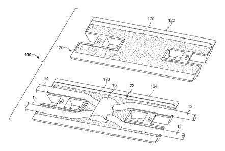
[0029] With reference to Figures 1-10, a sealant-filled enclosure assembly 100
according to some embodiments of the present invention is shown therein. The
enclosure
assembly 100 is adapted to form a sealed enclosure about a connection and/or
cables or the
like. For example, the enclosure assembly 100 may be used to form an
environmentally
protective enclosure about a plurality of cables 12, 14 (e.g., electrical
power lines) joined by a
connector 16 to form a connection assembly 9 as best shown in Figures 6-10.
[0030] With reference to Figure 1, the sealant-filled enclosure 100 includes a
housing
120 including a first shell or cover member 122 and a second shell or cover
member 124
adapted to be relatively positioned between an open position as shown in
Figure 1 and a
CA 02743900 2011-05-16
WO 2010/059619 PCT/US2009/064778
closed position as shown in Figure 6. Optionally, the cover members 122, 124
can be joined
by a hinge (e.g., a living hinge). Masses of sealant 170, 180 are disposed in
the cover
members 122. 124. According to some embodiments, and as discussed in more
detail below.
each of the sealants 170, 180 may be a gel. In the open position, the
enclosure assembly 100
can receive the connector 16 and adjacent portions of the conductors 12, 14.
In the closed
position, the enclosure assembly 100, including the sealants 170, 180, may
operate to seal
about and environmentally protect the connector 16. In the closed position,
the enclosure
assembly 100 defines an enclosure cavity 106 (Figures 7 and 9) and opposed
pairs of ports
108 (Figure 6) communicating with the enclosure cavity 106.
[0031] Turning to the housing 120 in more detail and as best seen in Figures 2-
5, the
cover members 122, 124 are constructed in generally the same manner. Each
cover member
122, 124 includes a bottom wall 130. Opposed side walls 132 and opposed end
walls 134
extend upwardly from the bottom wall 130. Opposed pairs of port extensions 140
extend
longitudinally from either end of each cover member 122, 124. Each port
extension 140 is
terminated by a port wall 142. According to other embodiments, the port walls
142 may be
frangible. For example, the port walls 142 may include corrugations comprising
a series of
fingers joined by relatively thin membranes as shown. According to other
embodiments, the
port walls may be rigid or semi-rigid breakaway panels releasably secured
closed by frangible
regions.
10032] The upper edges of the walls 132, 134 form a perimeter edge 138
defining an
opening 138A. The walls 130, 132, 134 and the port extensions 140 of each
cover member
122, 124 define an overall cover member chamber or cavity 136 communicating
with opening
138A. The cavity 136 includes a main cavity portion 136A and conductor port
subchannels
136B defined within each port extension 140.
[0033] Opposed tie slots 146 are defined in each cover member 122, 124. Ties
30 can
be used to secure the cover members 122, 124 together as shown in Figures 6
and 7. Other
mechanisms may be used to secure the cover members 122, 124 together such as
snaps or
latches.
[0034] Each cover member 122, 124 further includes an adjustable sealant
volume
control system 151. Each system 151 includes a pair of opposed sealant valve
mechanisms
150 each located between a respective pair of the port subchannels 136B. The
mechanisms
150 may be constructed and operate in substantially the same manner and,
therefore, only one
6
CA 02743900 2011-05-16
WO 2010/059619 PCT/US2009/064778
of the mechanisms 150 will be described in detail hereinafter, it being
appreciated that such
description likewise applies to the other mechanism 150.
[0035] The sealant valve mechanism 150 includes an overflow chamber 156 and a
valve port 152 fluidly connecting the chamber 156 with the cavity 136. The
mechanism 150
further includes a gate member 154 that, in a closed position as shown in
Figure 2, spans the
port 152 (Figures 2 and 10) to prevent or substantially eliminate fluid
communication
between the chamber 156 and the cavity 136. The gate member 154 may be a
substantially
rigid member or panel. The gate member 154 is pivotally joined to the bottom
wall of the
cover member 122, 124 by a hinge 154A (e.g., a living hinge; Figure 2).
Frangible connector
portions 154B releasably secure the gate member 154 to sidewalls 154C to hold
the gate
member 154 in the closed position. When the connector portions 154B are
severed, the gate
member 154 can be pivoted about the hinge 154A into one or more open positions
to provide
fluid communication between the cavity 136 and the chamber 156 through the
port 152. The
mechanism 150 further includes an outlet 158 to the environment and a base
stop wall 160.
[0036] The housing 120 may be formed of any suitable material. According to
some
embodiments, the housing 120 is formed of or with an electrically insulative
material. In
some embodiments, the housing 120 is formed of a vacuum formed or molded
polymeric
material. The housing 120 may be formed of polypropylene, nylon, polyethylene,
ABS and/or
PMMA. The housing 120 may be formed of a flame retardant material. The housing
material
may be any color or transparent.
[0037] Prior to use, the sealant 170 may be contained in the cavity 136 of the
cover
member 122 such that a main sealant portion of the sealant is disposed in the
main cavity 136
and port sealant portions are disposed in the port subehannels 136B. Prior to
use, the sealant
180 may be contained in the cavity 136 of the cover member 124 such that a
main sealant
portion of the sealant is disposed in the main cavity 136 and port sealant
portions are disposed
in the port subchannels 136B.
[00381 The sealants 170, 180 may be any suitable sealants. According to some
embodiments, the sealants 170, 180 are gel sealants. As used herein, "gel"
refers to the
category of materials which are solids extended by a fluid extender. The gel
may be a
substantially dilute system that exhibits no steady state flow. As discussed
in Ferry,
"Viscoelastic Properties of Polymers," 3rd ed. P. 529 (J. Wiley & Sons, New
York 1980), a
polymer gel may be a cross-linked solution whether linked by chemical bonds or
crystallites
7
CA 02743900 2016-05-17
30253-30
or some other kind of junction. The absence of the steady state flow may be
considered to be
the definition of the solid-like properties while the substantial dilution may
be necessary to
give the relatively low modulus of eels. The solid nature may be achieved by a
continuous
network structure formed in the material generally through crosslinking the
polymer chains
through some kind of junction or the creation of domains of associated
substituents of various
branch chains of the polymer. The crosslinkine can be either physical or
chemical as lone as
the crosslink sites may be sustained at the use conditions of the eel.
[00391 Gels for use in this invention may be silicone (oreanopolysiloxane)
gels; such
as the fluid-extended systems taught in U.S. Pat. No. 4,634,207 to Debbaut
(hereinafter
"Debbaut '207"); U.S. Pat. No. 4;680,233 to Camin et al.; U.S. Pat. No.
4;777;063 to Dubrow
et al.; and U.S. Pat No, 5,079;300 to Dubrow et al. (hereinafter "Dubrow
'300").
These fluid-
extended silicone eels may be created with nonreactive fluid extenders as in
the previously
recited patents or with an excess of a reactive liquid; e.g., a vinyl-rich
silicone fluid; such that
. it acts like an extender; as exemplified by the Syleard 527 product
commercially available
from Dow-Corning of Midland, Michigan or as disclosed in U.S. Pat. No.
3;020;260 to
Nelson. Because curing is generally involved in the preparation of these gels;
they are
sometimes referred to as thermosetting gels. The gel may be a silicone gel
produced from a
mixture of divinyl terminated polydimethylsiloxane, tetrakis
(dimethylsiloxy)silane; a
platinum divinyltetramethyldisiloxane complex, commercially available from
United
Chemical Technologies, Inc. of Bristol; Pennsylvania; polydimethylsiloxane;
and 1,3,5,7-
tetravinyltetra7methylcyclotetrasiloxane (reaction inhibitor for providing
adequate pot life).
[0040] Other types of gels may be used, for example, polyurethane gels as
taught in
the aforementioned Debbaut '261 and U.S. Pat. No. 5,140,476 to Debbaut
(hereinafter
"Debbaut '476") and gels based on styrene-ethylene butylenestyrene (SEBS) or
styrene-
ethylene propylene-styrene (SEPS) extended with an extender oil of naphthenic
or
. . nonammatic or low aramatic content hydrocarbon oil, as described in
U.S. Pat. No. 4,369;284
to Chen; U.S. Pat. No. 4,716,183 to Gamarra etal.; and U.S. Pat. No. 4;942;270
to Gamma.
The SEBS and SEPS eels comprise glassy styrenic microphases interconnected by
a fluid-
extended elastomeric phase. The microphase-separated styrenic domains serve as
the
junction points in the systems, The SEBS and SEPS eels are examples of
thermoplastic
systems.
[0041] Another class of gels which may be used are EPDM rubber-based eels, as
8
CA 02743900 2011-05-16
WO 2010/059619 PCT/US2009/064778
described in U.S. Pat. No. 5,177,143 to Chang etal.
[00421 Yet another class of gels which may be used are based on anhydride-
containing polymers, as disclosed in WO 96/23007. These gels reportedly have
good thermal
resistance.
[0043] The gel may include a variety of additives, including stabilizers and
antioxidants such as hindered phenols (e.g. IrE.,,anoxll 1076, commercially
available from
Ciba-Geigy Corp. of Tarrytown, New York), phosphites (e.g., IrgafosTM 168,
commercially
available from Ciba-Geigy Corp. of Tarrytown, New York), metal deactivators
(e.g.,
IrganoxTM D1024 from Ciba-Geigy Corp. of Tarrytown, New York), and sulfides
(e.g.,
Cyanox LTDP, commercially available from American Cyanamid Co. of Wayne, New
Jersey), light stabilizers (e.g., Cyasorb UV-531, commercially available from
American
Cyanamid Co. of Wayne, New Jersey), and flame retardants such as halogenated
paraffins
(e.g.. Bromoklor 50, commercially available from Ferro Corp. of Hammond.
Indiana) and/or
phosphorous containing organic compounds (e.g., Fyrol PCF and Phosflex 390,
both
commercially available from Akzo Nobel Chemicals Inc. of Dobbs Ferry, New
York) and
acid scavengers (e.g., DHT-4A, commercially available from Kyowa Chemical
Industry Co.
Ltd through Mitsui 8z Co. of Cleveland. Ohio, and hydrotalcite). Other
suitable additives
include colorants, biocides, tackifiers and the like described in -Additives
for Plastics,
Edition 1" published by D.A.T.A., Inc. and The International Plastics
Selector, Inc., San
Diego, Calif.
[00441 The hardness, stress relaxation, and tack may be measured using a
Texture
Technologies Texture Analyzer or like machine, having a load cell to measure
force, a 5 gram
trigger, and 1/4 inch (6.35 mm) stainless steel probe. For measuring the
hardness, for example,
of a 20mL glass vial containing 12 grams of gel, the probe is forced into the
gel at the speed
of 0.2 mm/see to a penetration distance of 4.0 mm. The hardness of the gel is
the force in
grams required to force the probe at that speed to penetrate the gel specified
for 4.0 mm.
Higher numbers signify harder gels.
100451 The tack and stress relaxation are read from the stress curve generated
by
tracing the force versus time curve experienced by the load cell when the
penetration speed is
2.0 mm/second and the probe is forced into the gel a penetration distance of
about 4.0 mm.
The probe is held at 4.0 mm penetration for 1 minute and withdrawn at a speed
of 2.00
mm/second. The stress relaxation is the ratio of the initial force (F)
resisting the probe at the
pre-set penetration depth minus the force resisting the probe (Fi) after 1 min
divided by the
9
CA 02743900 2016-05-17
30253-30
initial force F1, expressed as a percentage. That is, percent stress
relaxation is equal to
(Fr F f
1.- X100%
[00461 where F, and Fare in grams. In other words, the stress relaxation is
the ratio
of the initial force minus the force after 1 minute over the initial force. It
may be considered
to be a measure of the ability of the gel to relax any induced compression
placed on the gel.
The tack may be considered to be the amount of force in grams resistance on
the probe as it is
- pulled out of the gel when the probe is withdrawn at a speed of 2.0
mm/second from the
preset penetration depth.
[0047] An alternative way to characterize the gels is by cone penetration
parameters
according to ASTM D-217 as proposed in Debbaut '261; Debbaut '207; Debbaut
'746; and
'U.S. Pat. No. 5,357,057 to Debbaut et al.
Cone penetration ("CP") values may ranee from about 70 (10' mm)to about 400
(10-i mm). Harder gels may generally have CP values from about 70 (10-1 mm) to
about 70
(10-I mm). Softer gels may generally have CP values from about 200 (101 mm) to
about 400
(10-I mm), with particularly preferred range of from about 250 (1(11 mm) to
about 375 (1 0-1
mm). For a particular materials system, a relationship between CP and Voland
gram hardness
.can be developed as proposed in U.S. Pat. No. 4,852,646 to Dittmer et al.
[0048] According to some embodiments, the gel has a Voland hardness, as
measured
by a texture analyzer, of between about 5 and 100 grams force. The gel may
have an
elongation, as measured by ASTM D-638, of at least 55%. According to some
embodiments,
the elongation is of at least 100%. The eel may have a stress relaxation of
less than 80%.
The gel may have a tack greater than about I gram.
[0049] While, in accordance with some embodiments, the sealants 170, 180 are
gels
as described above, other types of sealants may be employed. For example, the
sealants 170,
180 may be silicone grease or hydrocarbon-based carcase.
[0050) The enclosure assembly 100 may be formed in the following manner. The
cover
members 122, 124 can be molded (e.g., injection molded or vacuum formed).
According to
other embodiments, the cover members 122, 124 are integrally formed with a
hinge and may
be unitarily molded.
[0051] If the sealant 170, 180 is a material, such as a curable gel, that
requires curing,
the sealant may be cured in sini,
CA 02743900 2011-05-16
WO 2010/059619 PCT/US2009/064778
[0052] The enclosure assembly 100 can be used as follows in accordance with
methods of the present invention to form the enclosed connection 9 (Figures 6-
9). A
connection 22 is first formed by installing the connector 16 on the conductors
12, 14. The
sealant valve mechanisms 150 may be set or adjusted as described below to
desirably control
displacement of the sealant. Thereafter, the enclosure assembly 100 is
installed over the
connection 22 and portions of the conductors 12, 14. The enclosure assembly
100 may be
held in an open position as shown in Figure 1 and the connection 22 may be
inserted into one
of or between the cover members 122, 124. The enclosure assembly 100 is then
closed by
urging one or both of the cover members 122, 124 together as shown in Figures
6-9, and then
secured in this position by installing tie wraps 30 through the tie slots 146.
Latches or clips
may be used to secure the cover members 122, 124, as well.
[0053] The closed housing 120 defines an enclosure cavity 106 including a main
enclosure cavity and contiguous port channels 109 (Figure 8; collectively
defined by the port
extensions 140). The connection 22 is encapsulated within the sealant 170,
180, and the
sealant 170, 180 and the connection 22 are in turn encapsulated within the
housing 120 (i.e.,
contained within the enclosure cavity 106). The portions of the conductors 12,
14 within the
connection 22 and extending from the connection 22 and through the port
channels 109 to the
port walls 142 are likewise encapsulated in the sealant 170, 180.
[0054] Prior to or as the enclosure assembly 100 is closed, the conductors 12,
14 may
break or splay the frangible walls 142 so that the conductors 12, 14 pass
therethrough and are
generally surrounded thereby. Because the walls 142 may be angled outwardly,
they tend to
be splayed outwardly by the conductors 12, 14.
[0055] According to some embodiments and as illustrated, the volumes and
configurations of the sealants 170, 180 are selected to ensure that the
connection 22 displaces
at least one, and according to some embodiments, both of the sealants 170, 180
when the
enclosure assembly 100 is transitioned from the opened position to the closed
position with
the connection 22 disposed therein.
[0056] According to some embodiments, the combined volume of the connector 16,
the portions of the conductors 12, 14 in the enclosure cavity 106, and the
sealants 170, 180 is
greater than the volume of the enclosure cavity 106.
[0057] According to some embodiments, when the enclosure assembly 100 is
installed as described herein, the closing of the cover members 122, 124 about
the connection
11
CA 02743900 2011-05-16
WO 2010/059619 PCT/US2009/064778
22 forcibly displaces the sealants 170, 180 about the connector 16 such that
the sealants 170,
180 flow around the connector 16 and, in some cases, into interstices within
the connector 16.
According to some embodiments, the sealants 170, 180 substantially fully
encapsulate the
connector 16.
[0058] The sealant valve mechanisms 150 may be used to adjust or tune the
performance or effective capacity of the enclosure assembly 100. For example,
the enclosure
assembly 100 may be configured for use with connections 22 that are relatively
large or small
in size. In order to provide a satisfactory sealant seal for a small
connection 22, at least a
certain volume of the cavities 136 must be filled with the sealants 170, 180.
However, when
the enclosure assembly 100 is to be installed on a large connection 22, the
connection 22 may
displace so much sealant 170, 180 that the cover members 122, 124 cannot he
closed without
undue effort.
[0059] In the case of a small connection 22, the operator can leave the valve
gate
members 154 in their closed positions. The gate members 154 will remain closed
and the
sealants 170, 180 will be displaced in known manner when the cover members
122, 124 are
closed, as shown in Figures 7-9. That is. the sealants 170, 180 are prevented
from flowing
into the chambers 156 by the gate members 154.
[0060] In the case of a large connection 22, the operator can break away the
valve gate
member 154 of each valve mechanism 150 and pivot it down about the hinge 154A
into the
confined space of the chamber 156 to open the valve port 152. As the cover
members 122,
124 are closed, the displaced sealant 170, 180 will be expelled or exuded
through the ports
152 and into the chambers 156 as shown in Figure 10. In this manner, the
effective volume
of the cavity 106 is supplemented by the volumes of the chambers 156. As a
result, the
internal pressure of the sealant 170,180 is reduced, allowing easier closing
of the cover
members 122, 124.
[0061] As discussed above, according to some embodiments, each gate member 154
is substantially rigid or semi-rigid. According to some embodiments, the
stiffness of each
gate member 154 is sufficient to withstand a pressure from the interior side
(i. e. , the cavity
136 side) of at least 0.2 psi, and according to some embodiments at least 0.5
psi, without
deforming or deflecting an amount sufficient to permit the sealant 170, 180 to
pass through
the corresponding port 152.
12
CA 02743900 2011-05-16
WO 2010/059619 PCT/US2009/064778
[0062] According to some embodiments, the connection(s) between each gate
member 154 and the housing 120 (e.g., the frangible connector portions 154B)
are sufficient
to require at least 0.2 psi, and according to some embodiments at least 0.5
psi, of pressure on
the interior side to break the gate member 154 away and open the corresponding
port 152.
According to some embodiments, a minimum gate opening force of at least 0.2
pounds-force,
and according to some embodiments at least 0.5 pounds-force, must be applied
to the gate
member 154 in order to open the gate member.
[0063] Further levels of adjustment may be set as well. The operator may
selectively
open the gate members 154. For example, in one configuration, one of the gate
members 154
may be open and the other gate member 154 remains closed.
[00641 While the foregoing procedures are described as including a step of the
operator breaking away the gate members 154, according to some embodiments the
operator
does not break away the gate members 154. Instead, the gate member connector
portions
154B are left intact and configured such that they automatically tear and
permit the gate
members 154 to be opened when the internal pressure of the sealant 170, 180
exceeds a
prescribed threshold pressure. The threshold pressure may be exceeded during
installation
(i.e., as the cover members 122, 124 are being closed) or when the temperature
of the sealant
170, 180 is elevated causing volumetric thermal expansion of the sealant 170,
180.
[0065] According to some embodiments, the volume of each chamber 156 when the
associated gate member 154 is opened to the base stop 160 is in the range of
from about 2 to
50 percent.
[0066] By selectively configuring the valve mechanisms 150, the operator may
ensure
that the housing 120 can be closed without requiring undue force, but
nonetheless that the
sealants 170, 180 are displaced and forced to flow about the connection 22 and
also that the
sealants 170, 180 sufficiently engage with one another at the interface
between the cover
members 122, 124 to provide adequate insulation and sealing.
[0067] The valve mechanisms 150 can also provide a controlled space for the
sealant
170, 180 to expand into and out of and still maintain the desired insulation
and sealing. For
example, when pressure is created during a heating cycle, the sealant 170, 180
will expand
into the chambers 156, and then recover and retract from the chambers 156 into
the main
cavity 106 as the sealant 170, 180 cools.
[0068] In some embodiments, an opening 156A is present in the housing 120 and
1:3
CA 02743900 2011-05-16
WO 2010/059619 PCT/US2009/064778
connects the chamber 156 to the exterior of the housing 120. These openings
156A may be
provided to facilitate molding of the housing 120. These openings 156A may
also provide a
path for air to escape from the chambers 156 as sealant 170, 180 enters the
chambers 156.
According to some embodiments, the housing 120 is configured such that the
gate members
154 when open will close off at least a portion of the openings 156A to
prevent or inhibit the
sealant 170, 180 from escaping through the openings 156A (i.e., provide a
closed chamber
156). In some embodiments, the gate members 154 close off a majority of each
associated
opening 156A and, in some embodiments, fully close off the openings 156A.
[0069] While the valve mechanisms 150 are illustrated located between the
conductor
port subchannels 136B, other locations may be employed as appropriate for the
intended
cable/connector configurations.
[0070] As will be appreciated from the description herein, the sealant 170,
180
engages portions of the conductors 12, 14 to form seals thereabout. The
sealant 170, 180 also
forms a sealing block that surrounds the connector 16, thereby sealing the
connector 16.
Notably, in the illustrated enclosure assembly 100, the sealant masses 170,
180 connect with
one another to encapsulate the connector 16 and conductors 12, 14.
[0071] The enclosure assembly 100 may be sized and configured to accommodate
and
seal multiple or a range of sizes of connectors 16 and conductors 12, 14.
[0072] The enclosure assembly 100 may provide a number of advantages. The
enclosure assembly 100 may provide a reliable seal about the connection 22.
This seal may
prevent or inhibit the ingress of moisture that would otherwise cause
corrosion of the
connection 22. The sealant 170, 180, particularly gel sealant, may accommodate
conductors
of different sizes within a prescribed range. The interfacing sealant masses
170, 180 and the
relationship between the connector or connection volume and the sealant
volumes may ensure
that a suitable seal is provided by and between the sealant masses for a
broadened range of
sizes connections 22 positioned in the enclosure assembly 100.
[0073] When the sealant 170, 180 is a gel, the conductors 12, 14 and the
housing 120
may apply a compressive force to the sealant 170, 180 as the assembly 100 is
transitioned
from the open position to the closed position. The gel may thereby be
elongated and be
generally deformed and substantially conform to the outer surfaces of the
connector 16, the
conductors 12, 14 and to the inner surface of the housing 120. Some shearing
of the gel may
occur as well. At least some of the gel deformation may be elastic. The
restoring force in the
14
CA 02743900 2011-05-16
WO 2010/059619 PCT/US2009/064778
gel resulting from this elastic deformation generally causes the gel to
operate as a spring
exerting an outward force between the housing 120 and the connector 16 and the
conductors
12, 14. The compressive loading and restoring force are maintained by the
closure of the
cover members 122, 124.
[0074] Various properties of the gel as described above may ensure that the
gel
sealant 170, 180 maintains a reliable and long lasting seal between the
housing 120 and the
connector 16 and the conductors 12, 14. The elastic memory of and the retained
or restoring
force in the elongated, elastically deformed gel generally cause the gel to
bear against the
mating surfaces of the connector 16, the conductors 12, 14 and the interior
surface of the
housing 120. Also, the tack of the gel may provide adhesion between the gel
and these
surfaces. The gel, even though it is cold-applied, is generally able to flow
about the connector
16, the conductors 12, 14 and the housing 120 to accommodate their irregular
geometries.
[0075] According to some embodiments, the sealant 170, 180 is a self-healing
or self-
amalgamating gel. This characteristic, combined with the aforementioned
compressive force
between the connector 16, conductors 12, 14 and the housing 120, may allow the
sealant 170,
180 to re-form into a continuous body if the gel is sheared by the insertion
of the conductors
12, 14 into the enclosure assembly 100. The gel may also re-form if the
connector 16 and
conductors 12, 14 are withdrawn from the gel.
[0076] The sealant 170, 180, particularly when formed of a gel as described
herein, may
provide a reliable moisture barrier for the conductors 12, 14 and the
connector 16, even when
the enclosure assembly 100 is subjected to extreme temperatures and
temperature changes. The
housing 120 may be made from an abrasion resistant material that resists being
punctured by the
abrasive forces.
[0077] The gel sealant may also serve to prevent or inhibit corrosion of the
connection
22 by depositing a layer of oil from the gel on the exposed surfaces of the
connector 16 and
conductor portions 12, 14 in the enclosure cavity 106. Even if the gel is
removed from the
connection 22, the oil may remain to coat the connection surfaces as a barrier
to moisture.
[0078] With reference to Figures 11-15, a sealant-filled enclosure assembly
200
according to further embodiments of the present invention is shown therein,
The enclosure
assembly 200 is constructed in the same manner as the enclosure assembly 100
except that
each valve mechanism 250 (corresponding to the valve mechanism 150) of the
enclosure
CA 02743900 2011-05-16
WO 2010/059619 PCT/US2009/064778
assembly 200 further includes a supplemental stop member or tab 262 pivotally
mounted via
a living, hinge 262A.
[0079] In use, the operator may selectively configure the enclosure assembly
200 to
accommodate a small, medium or large connection 22. Configuration for a small
or large
connection 22 can be executed as discussed above with regard to the enclosure
assembly 100.
[00801 In the case of a medium connection 22, the operator can bend each
supplemental stop member 262 from its stored position (Figures 11 and 14) to a
deployed
position (Figure 15). The operator can break away the valve gate member 254 of
each valve
mechanism 250 and pivot it down about the hinge 254A to open the valve port
252. As the
cover members 222, 224 are closed, the displaced sealant 270, 280 will be
expelled or exuded
through the ports 252 and into the chambers 256. The pivot of the gate members
254 is
limited by the respective supplemental stop member 262. In this manner, the
effective
volume of the cavity 206 is supplemented by the volumes of the chambers 256.
However,
because the gate member 254 is only permitted to pivot to a partially open
position, the
supplemental volume provided by the chambers 256 will be less than in the case
where the
gate members 254 are opened to the base stops 260. Thus, each valve mechanism
250 can be
selectively adjusted to provide three different volumes to contain the sealant
170, 180.
[0081] According to some embodiments, the volume of each chamber 256 when the
associated gate member 254 is opened to the base stop 260 is in the range of
from about 1 to
50 percent and the volume of each chamber 256 when the associated gate member
254 is
opened to the supplemental stop member 262 is in the range of from about 1 to
25 percent.
[0082] As will be appreciated from the description herein, enclosure
assemblies
according to the present invention may be provided as pre-formed and fully
assembled units,
with pre-cured gel or other sealant therein as described above, that may be
cold applied about
a connection to form a seal.
[0083] It will be appreciated that enclosures in accordance with the present
invention
may have components (e.g, cover members, walls, etc.) and cavities or chambers
having
shapes, configurations and/or sizes different than those shown and described
herein.
[0084] Embodiments of the present invention have been described above and,
although specific terms are employed, they are used in a generic and
descriptive sense only
and not for purposes of limitation. The following claim is provided to ensure
that the present
application meets all statutory requirements as a priority application in all
jurisdictions and
16
CA 02743900 2011-05-16
WO 2010/059619
PCT/US2009/064778
shall not be construed as setting forth the scope of the present invention.
17