Note: Descriptions are shown in the official language in which they were submitted.
CA 02744084 2011-06-16
METHOD AND APPARATUS FOR MARINE SOURCE
DIAGNOSTICS AND GUI FOR OPERATING SAME
Background of the Invention
1. Field of the Invention
[0001] This invention relates generally to marine seismic surveys and more
particularly
to a method and apparatus for synthesizing and analyzing the output response
of an air-
gun array and for displaying information over a graphical user interface to a
user for real-
time quality control of a seismic survey operation.
2. Description of the Related Art
[0002] In marine seismic surveying, to obtain geophysical information relating
to the
substrata located below the sea bottom, seismic sources, generally acoustic
transmitters, adapted to produce pressure pulses or shock waves under water,
are
towed beneath the water surface behind a marine vessel. The shock waves
propagate
into the substrata beneath the sea where they are reflected back to the sea.
Sensors
(usually hydrophones) are used to detect the returning shock waves and to
output
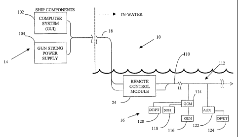
signals indicative of the detected wave. The signals are processed to generate
useful
data and to determine the geophysical structure of the substrata.
[0003] Air guns or gas guns are frequently used as acoustic transmitters.
Usually,
several air guns are placed in spaced relation to each other in an array. One
or more air
gun arrays are towed behind a marine vessel beneath the sea surface. During
operation,
all air guns in an array are activated simultaneously to produce a desired
overall
pressure pulse from that array. The pulse characteristics, such as the
frequency, bubble
ratio and amplitude, of the overall pressure pulse produced by an air gun
array is a
function of the characteristics of the pressure pulses produced by the
individual air guns
and the physical arrangement of the air guns in that air gun array and of each
gun in that
array.
CA 02744084 2011-06-16
[0004] Usually, a shipboard central controller controls the array, and the
controller is
coupled to the array by an umbilical leading out to the array. Shipboard
controllers have
been improved over the years to help ensure simultaneous activation (or
firing) of the air
guns. One such system is described in U.S. patent 4,757,482 to Fisk and having
the
title "Modular Airgun Array Method, Apparatus and System", the '482 patent.
That
patent describes an air gun control system having a central controller on the
ship with a
data bus leading to several sources aligned in an array and towed behind the
ship. The
controller of the '482 patent provides some in-water control features by the
use of a
plurality of local control modules that perform power conversion and are
individually
addressable by the shipboard central controller.
[0005] Marine seismic surveyors have several goals for managing energy source
output.
One goal is to maximize the energy output of the seismic source array. Another
goal is
to maintain the array operational characteristics within a predetermined set
of
specifications or limit conditions. Energy produced by a source array is
maximized by
maintaining the proper timing of array elements and by monitoring individual
elements
for out-of-tolerance conditions. The term "array" refers to multiple air guns
activated
simultaneously. The term "element" refers to a single air gun. The term source
or
acoustic source as used herein generically refers to either a single air gun
or to an array
of air guns.
[0006] Timing is problematic with typical source systems that control timing
from the
acquisition vessel. A telemetry cable that extends from the vessel to the
source element
acts as a filter in the system and it limits the operator's ability to
precisely control element
timing. Source elements that are not precisely timed will produce energy that
interferes
and reduces the overall array output. Moreover, data signals returning from
hydrophone
acoustic sensors will also suffer from the same imprecision.
[0007] System operators normally use assumptions about a source array
signature
when processing seismic data signals to recover the true reflectivity of the
subsurface by
suppressing distortions. The usual processing methods use deconvolution
techniques,
which are adversely affected when initial assumptions are inaccurate.
Therefore, as an
array output degrades due to timing or element errors, the initial assumptions
become
less accurate and thus reduce the reliability of the processed data signals.
[0008] Another problem with the typical prior art system is that element
failure often
reduces operational effectiveness. A failed source in an array adversely
affects initial
2
CA 02744084 2011-06-16
assumptions by changing the array combined output pulse. If detected, the
operator
might continue operation with a small number of failures, but this reduces
data quality.
Also, the operator might install spare elements in the array to activate
subsequent to the
failure, but this adds cost to the survey operation. Ultimately, the operator
might be
forced stop production to retrieve and repair the source array, resulting in
significant
efficiency losses.
[0009] These and other problems with the typical seismic survey system create
a need
for an apparatus and method for determining real-time an array health status
from which
the operator can make an informed real-time decision for continuing a survey
with a
failed element. As used herein, the term real-time means any course of action
or activity
during a seismic survey.
[0010] The typical system also suffers from an inability to provide
information useful in
predicting system response given a potential failure. Therefore, the need
exists for
predictive array synthesis that takes element failure into account. Such array
synthesis
will allow an operator to predict array performance with one or more elements
removed
from the array and to determine if the array would remain within
specifications given the
removed elements.
[0011] Yet another problem associated with the typical system is that the
operator
needs an improved interface for effectively controlling the array in view of
potential
failures. Current seismic survey systems do not provide a graphical user
interface
having real-time status reporting, quality control reporting, or
troubleshooting tips for use
during the survey.
Summary of the Invention
[0012] The present invention addresses the above-identified drawbacks by
providing a
seismic data acquisition system having improved graphical user interface,
prediction
control through array synthesis, and real-time source monitoring and
correction.
[0013] In one aspect of the invention a method of testing an acoustic source
during a
seismic survey operation comprises creating a baseline signature of the
acoustic source,
creating a second signature from the acoustic source during the seismic survey
operation, and comparing the second signature to the baseline signature, the
comparison being used at least in part in determining a course of action.
3
CA 02744084 2011-06-16
[0014] The baseline signature represents one of a measured near-field air gun
output or
a synthesized far-field array output based on predetermined initial
parameters. When
the baseline signature represents a near-field output, the second signature
preferably
represents a near-field output. When the baseline signature is a synthesized
far-field
signature, the second signature is a synthesized far-field signature based on
survey
derived parameters. The signatures can be in a time domain and/or a frequency
domain.
[0015] Another aspect of the invention is a method of testing an acoustic
source during
a seismic survey comprising generating a near-field signature (acoustic or
pressure
gradient) using the acoustic source and storing the near-field signature as a
baseline
signature. A far-field signature is synthesized using predetermined initial
parameters.
The method includes generating a second near-field signature during the
seismic survey
using the acoustic source, synthesizing a second far-field signature using
survey derived
parameters, comparing the second near-field signature the baseline signature
during the
survey, comparing the second synthesized far-field signature to the first
synthesized far-
field signature to the first far-field signature, and determining a course of
action based at
least in part on one of the comparison of the near-field signatures and the
comparison of
the synthesized far-field signatures.
[0016] Yet another aspect of the present invention is a method of testing an
acoustic
source during a seismic survey comprising synthesizing a first far-field
signature using
predetermined initial parameters such as depth, pressure temperature, and
timing
expected during the survey. Then the method includes activating the acoustic
source to
conduct the seismic survey, synthesizing a second far-field signature using
survey
derived parameters, comparing the second far-field signature to the first far-
field
signature, and determining a survey course of action based at Idast in part on
the
comparison.
[0017] Another aspect of the present invention is an apparatus for testing an
acoustic
source during a seismic survey operation, comprising a sensor to sense a first
output of
the acoustic source and a second output of the acoustic source during the
seismic
survey. The apparatus includes a memory device for storing a baseline
signature
representative of the first sensed output, and a processor executing
instructions
according to one or more programs stored in the memory device for comparing a
second
signature representative of the second sensed output to the baseline
signature, the
4
CA 02744084 2011-06-16
comparison being used at least in part in determining a course of action
during the
seismic survey.
[0018] Still another aspect of the present invention is an apparatus for
testing an
acoustic source during a seismic survey operation, comprising a controller
controlling the
acoustic source, a memory device in the controller for storing a baseline
signature
representative of the acoustic source output and a second signature
representative of a
subsequent output of the acoustic source, and a processor executing
instructions
according to one or more programs stored in the memory device for comparing
the
second signature to the baseline signature, the comparison being used at least
in part in
determining a course of action during the seismic survey.
[0019] The present invention further provides a seismic data acquisition
system having
improved graphical user interface, prediction control through array synthesis,
and real-
time source monitoring and correction.
[0020] A seismic survey information presentation device is provided for use
with a
seismic survey system including one or more acoustic sources. The device
includes a
computer having a processor for processing information according to one or
more
programs, a display device for displaying the processed information, an
information input
device for providing a user entry point into the information presentation
device, the
processor, display device and information input device being a graphical user
interface,
one or more sensors associated with the seismic operatively coupled to the
computer for
transferring real-time survey information to the computer, and a plurality of
modules in
the computer for comparing survey derived parameters relating to an acoustic
source
signature to predetermined parameters relating to the acoustic source, wherein
the
comparison is reported to a user on the display during the seismic survey, the
comparison being used at least in part in determining a course of action.
[0021] In another aspect a baseline signature represents one of bubble period,
bubble
amplitude and frequency and a real-time comparison is made based on real-time
measurements.
[0022] The baseline signature can be a measured near-field air gun output or a
synthesized far-field array output based on predetermined initial parameters.
When the
baseline signature represents a near-field output, the second signature
preferably
represents a near-field output. When the baseline signature is a synthesized
far-field
5
CA 02744084 2011-06-16
signature, the second signature is a synthesized far-field signature based on
survey
derived parameters. The signatures can be in a time domain and/or a frequency
domain.
[0023] Still another aspect of the present invention is a troubleshooting
module in the
plurality of modules. The troubleshooting module uses the comparison in
determining
an out-of-tolerance condition and provides pre-planned troubleshooting tips to
the user
in, real-time to aide in determining the next course of action.
Brief Description of the Drawings
[0024] The novel features of this invention, as well as the invention itself,
will be best
understood from the attached drawings, taken along with the following
description, in
which similar reference characters refer to similar parts, and in which:
Figures IA and 1B show a marine seismic data acquisition system according to
the
present invention;
Figure 1C is a system block diagram that represents the system of Figures IA
and 1B;
Figure 1 D shows a computer system used for the GUI of the present invention;
Figure 2 is a block diagram of an embodiment of the remote control module of
the
present invention;
Figure 3 is a block diagram to show in greater detail the in-water components
used in
the system of Figure 1;
Figure 4 is a plot of a typical air gun response;
Figures 5A and 5B show a flow diagram of a method according to the present
invention;
Figure 6 is an acoustic source far-field signature (FFS) shown in the time
domain;
Figure 7 is an acoustic source far-field signature (FFS) shown in the
frequency domain;
and
6
CA 02744084 2011-06-16
Figures 8A-8B show a data flow diagram of a GUI control system according to
the
present invention.
Detailed Description of the Invention
[0025] Figures 1A and 1B show a marine seismic data acquisition system 10.
Shown
is a tow vessel 12 that includes a central controller 14. As described later,
the controller
14 includes a computer and graphical user interface. An air gun array 28 is
coupled to
the vessel by a reinforced cable 18 and known coupling 26. The cable 18
includes
conductors for coupling the array sources to the central controller. The array
comprises
several individual acoustic sources 16. When activated, each source produces
an air
bubble 20, and the individual sources are activated such that the several air
bubbles
coalesce to form a substantially singular acoustic wave 22. An in-water remote
control
module 24, which will be further described later, preferably controls each
array string.
[0026] As shown in Figure 113, each source comprises several components
according
to the present invention. Shown are two substantially identical source array
strings.
Each string includes preferably only one remote control module 24 the array
string.
Referring to Figures 113 and IC, a source element includes a gun control
module 114
for controlling the individual source, a hydrophone sensor 118 for acquiring a
near-field
response from each source, a depth transducer for acquiring depth information,
and a
pressure transducer for acquiring pressure information. The depth and pressure
transducers being shown collectively as a DT/PT module 120.
[0027] The central controller 14 includes a memory unit (not separately shown)
for
storing baseline element signatures as well as signatures acquired during the
seismic
survey. For the purposes of this invention a signature is a signal indicative
energy
associated with an air gun output or with an array output. The signal can be
measured
or synthesized. A graphical user interface according to the present invention
is included
for allowing an operator to view system and element status and for commanding
the
system from the vessel. As used herein, an element signature means information
representative of a source element response characteristic. The signature can
be a
single source signature or the signature can be a combination of signatures
from an
array of single sources. The signature can be a near-field signature or the
signature can
7
CA 02744084 2011-06-16
be a far-field signature. Furthermore, the signature can be measured, computed
or
synthesized using methods according to the present invention.
[0028] Figure 1C is a system block diagram that represents the system 10 of
Figures
1A and 1B. The system includes out-of-water (or shipboard) components and
towed in-
water components. Shipboard components include a graphical user interface
(GUI)
computer 102 and a power supply 104. The use of the term "shipboard
components" is
for simplicity and not indicative of a requirement that any particular
component be on a
ship. For example, one aspect of the present invention includes a network
interface that
transmits seismic data to a remote location such as in a land-based office to
be viewed
on a GUI monitor. The power supply 104 is preferably a known supply used for
converting alternating current (ac) power to direct current (DC) power.
[0029] The interface 102 and power supply 104 are coupled to in-water
components via
the umbilical 18. The umbilical 18 is connected to the array 28. The remote
control
module 24 is coupled via a second umbilical 110 to one or more source elements
16.
[0030] In a preferred embodiment, the shipboard interface communicates with a
navigation system and provides global synchronization to in-water components
to be
described later. The shipboard interface provides a data collection point for
source array
elements and peripheral sensors, and it provides an operator entry point for
control of
source array elements.
[0031] The array 18 includes a plurality of air gun control modules 114 (only
one is
shown for simplicity), and each gun control module is connected to and
controls at least
one air gun 116. The gun control module (GCM) is also connected to one or more
near
field hydrophones 118 and one or more depth/pressure transducers 120 (DT/PT
modules). The array may include an optional auxiliary unit 122 when additional
DT/PT
modules are desired.
[0032] Figure ID shows a one embodiment of the computer and the GUI of the
central
controller 14 of the present invention. The central controller preferably
includes a
computer 124, a monitor 126 and a keyboard 128. As in most typical computers,
the
computer 124 includes an internal processor, memory devices for storing
information
obtained during the survey and for storing one or more programs having
instructions for
use by the processor. The processor is preferably used to synthesize signals
and to
compare synthesized signals as well as to analyze and compare measured signals
8
CA 021744084 2011-06-16
received during the survey. These aspects of the present invention will be
further
described herein with respect to Figure 5.
[0033] Figure 2 is a block diagram of the remote control module (RCM) 24 used
as part
of system 10 described above and shown in Figure 1C. The RCM 24 includes a
processor 202, a telemetry communication module 204 and an optional global
positioning system (GPS) timing signal receiver 206. In a preferred
embodiment, DC
power is generated on ship using the power supply 104 as described above and
shown
in Figure 1. The RCM 24 preferably passes the DC power using a power bus 208,
and
the power bus 208 distributes the DC power along the array.
[0034] The RCM processor 202 may be any number of known processors and may
include a memory module 212 for storing received parameters and data. The
processor
202 is coupled to the telemetry module 204. The processor is coupled to the
GPS signal
receiver 206 for use when precise positioning is necessary as will be
discussed later.
The telemetry module is coupled to the shipboard interface 102 via a
communications
link. The telemetry module 204 is also coupled to the processor 202 and GPS
receiver
206. All internal couplings are typical electrical couplings known in the art.
[0035] Figure 3 is a block diagram to show in greater detail a preferred
arrangement of
the in-water components used in the system of Figure 1. The several components
shown in Figure 3 are referred to collectively as the towed subsystem 300. The
towed
subsystem 300 includes a remote control module (RCM) 302 substantially
identical to
the RCM 24 described above and shown in Figures 1 and 2. The RCM 302 is
coupled
to an array 304 using any suitable connector 306a to connect an array
umbilical 308.
The array umbilical 308 couples the RCM 302 to a plurality of branches 310a-
310b using
known T -connectors or any other suitable known connector.
[0036] A gun branch 310a includes a gun control module (GCM) 314. The GCM 314
is
coupled to a known air gun 316. The GCM 314 is coupled to a depth/pressure
transducer module 318. The GCM is coupled to a hydrophone 320.
[0037] Each GCM is a distributed controller for source array elements. Each
GCM
includes digitizing circuitry for digitizing signals at or near the acoustic
source location.
This local digitization reduces adverse noise effects and increases upstream
processing
capability. In a preferred embodiment, each GCM is used to digitize signals
from
peripheral sensors elements such as the DT/PT modules.
9
CA 02744084 2011-06-16
[0038] Each GCM provides power to the source element and acts as a single bus
between control units and all source elements, which reduces the number of
conductors
required for operation.
[0039] An auxiliary branch 310b is used to expand the capabilities of the gun
branch
310a. As such, the auxiliary branch is completely optional. When used, the
auxiliary
branch 310b preferably includes an auxiliary GCM 322. The auxiliary GCM is
coupled to
one or more depth/pressure transducer modules 324a-c. The auxiliary GCM is
similar
to the GCM in that the auxiliary GCM operates to digitize output signals from
the
auxiliary branch peripheral sensor elements such as the DT/PT modules 324a-c.
[0040] Referring now to Figures 4-8 and utilizing the embodiments described
above
and shown in Figures IA-3, real-time acoustic source testing embodiments and
graphical user interface (GUI) embodiments according to the present invention
will be
discussed.
[0041] Figure 4 is a graphical representation of a typical air gun response
shown as
amplitude plotted against time. When an air gun is activated, a peak amplitude
402 is
usually exhibited followed several successively decaying peaks, or so-called
bubble
amplitude peaks 404. An air gun operating within normal parameters will
usually exhibit
an asymptotic peak decay curve shown as a dotted line 406. The curve is a
diminishing
sinusoid with a period T 408 being, for example, (a + b) or (b + c). The
positive peak
amplitude is typically indicative of a direct output while the negative peak
amplitude
typically includes surface reflection energy usually present in the
measurement. Those
skilled in the art understand the effect of reflection energy on peak-to-peak
measurements and understand how to compensate measured data. Thus, the terms
peak and peak-to-peak might sometimes be used interchangeably. A measured
response characteristic that deviates significantly from the typical response
curve might
be indicative of problems with the air gun, the receiver hydrophone or both.
For
example, a wide variation in the period T is usually indicative of a problem
with the air
gun, whereas a variation in the amplitude response can be 'indicative of a
problem with
the gun or the hydrophone or both.
[0042] Since the problem cause is sometimes difficult to determine, the
typical
operations procedure would have the survey halted to replace the air gun
and/or the
hydrophone. This is because the typical system does not provide any indication
as to
the acceptability of continuing the survey with a failed gun and/or
hydrophone. If the
CA 02744084 2011-06-16
operator simply continues the survey, there is no measure or guarantee of the
accuracy
of the future survey data, thus diminishing the value of the survey.
[0043] The present invention provides a real-time test apparatus and procedure
that
uses a known response in conjunction with real-time measurement for
determining the
effectiveness of the array with a failed gun and or gun/hydrophone pair. Each
air gun in
the array of the. present invention is initially tested to create an initial
response
characteristic signature such as the response shown in Figure 4. The signature
is
known as a near-field signature, and is used for the purposes of the present
invention.
Preferably, the hydrophones used in the array are used in measuring individual
air gun
signatures. The signatures are stored as near-field baseline data in the
memory device
for later comparison to real time responses from the air gun elements as will
be
discussed in more detail later.
[0044] The initial measured air gun response provides information about the
health and
performance of the air gun when compared to an ideal. The response of each air
gun is
preferably represented in the time domain as shown. A period of each response
is
determined and archived for later comparison to real-time response signals.
Changes in
the response period tend to indicate a problem with the air gun. The initial
archived
signal also includes peak amplitude. Real-time response signals are compared
for peak
amplitude variations. Amplitude exceeding acceptable operational limits
(maximum or
minimum) tends to indicate a problem with the hydrophone or air gun.
[0045] Figures 5A-5B show a method according to the present invention that
provides
concurrent near field quality control and far field signature synthesis during
a seismic
survey. The flow shown is for ease of explanation and is not intended as
limiting the
invention to any particular order of steps.
[0046] The method begins by storing initial information in the central
controller for use in
later comparisons and by activating each element to measure and store a
baseline near-
field (NF) signature for each element 502. The initial information preferably
includes the
particular seismic survey array configuration, e.g., number of strings, number
of guns per
string, gun identifier etc... The information preferably includes tolerance
information
derived from component specifications as well as particular customer
requirements.
Other useful information used for synthesizing far-field (FF) signals and for
NF and FF
signal comparisons include gun volume, timing, temperature, depth, atmospheric
pressure, water pressure, and the like. The initial information is based on
expected
11
CA 02744084 2011-06-16
values for these parameters, while sensors as described above are used to
acquire real-
time information relating to the same parameters. The present invention
contemplates as
initialization information as being any desired information to be used to
compare survey
information for quality or to compare any component or subsystem operating
parameter
for quality.
[0047] A far-field (FF) signature (signal) is synthesized 504 based on the
actual array
configuration and on initial parameters and assumptions above. The synthesized
FF
signature is stored for later comparison to real-time synthesized FF
signatures derived
during the seismic survey using the measured parameters and constant known
parameters.
[0048] The survey begins by activating all sources 506 as is typical in the
art. At each
activation, commonly referred to as a "shot", a new NF signature is acquired
508 using
near field hydrophones. Information associated with the shot is acquired. This
survey
derived information is acquired through in-water sensors, e.g., the DT/PT 120,
temperature sensors, atmospheric sensors, GPS devices, etc... Other
information
relating to the array configuration and individual hydrophones is acquired and
stored in
the central controller memory for processing.
[0049] The newly acquired NF signatures (signals) are compared to the NF
baseline,
and a new FF signature is synthesized 510, based on the information acquired
during
the survey.
[0050] Preferably in a concurrent fashion, the newly-acquired NF signatures
are
compared with the baseline signatures and the new FF signature 512 is compared
to the
original FF signature 514. The NF signatures are preferably compared in the
time
domain for comparing amplitude peaks and zero crossings with the baseline
signatures
for the corresponding source. Additionally, the NF signature is compared in
the
frequency domain by measuring the first harmonic of the signature and
comparing the
measured first harmonic with the first harmonic of the baseline signature of
the
corresponding source. Substantially similar comparisons are conducted with the
FF
synthesized signature and the stored FF signature.
[0051] The FF signature comparison is then reported 518 via the GUI monitor in
substantially real-time, while further processing is performed on the measured
NF
signatures.
12
CA 02744084 2011-06-16
[0052] The method includes determining whether the each source is operating
within
predetermined specifications 518, based on the compared frequency and/or
amplitude
comparisons relating to the NF signatures. If all comparisons show that the
guns are
operating within specification, then the survey can continue with the
comparison results
being reported 520 via the GUI monitor.
[0053] When any particular acoustic source is not operating within
specification, the
method of the present invention allows for real-time assessment of continued
operations
with one or more failed acoustic sources. The newly-measured signatures are
used to
determine the survey can continue without using the failed sources 522. In
this case,
the new FF signature is synthesized 524 using the information as described
above and
with array configuration information revised to exclude the failed elements.
The new
synthesized FF signature is compared to FF signature specifications 526 and to
the
previously synthesized FF signature for real-time informed decision-making
regarding
continued operations. In some cases, the new synthesized signature might
indicate that
the missing sources will not adversely affect the quality of the survey, and
the survey
can continue by not activating the failed sources. In other cases, the new
synthesized
signature might indicate that further survey operations are not advisable due
to expected
poor quality.
[0054] In some cases, the NF comparison and FF comparison (with or without
excluded
elements), might show array drift. Array drift is a known condition whereby
substantially
all acoustic source NF signatures are altered in generally the same way. It is
possible
that some or all of the sources fail a specification, but the synthesized FF
signature
might indicate that useful data can be acquired by continued operations. In
this case,
the user has the option to update the specifications 528 and/or NF baseline
signature
using the new synthesized FF signature taking into account the drift
conditions. This
allows the survey to continue with the change in specifications being recorded
for later
evaluations. When this option is selected, the baseline signature 530 and
associated
specifications can be updated in real-time without halting the survey and
retrieving the
array.
[0055] Figure 6 represents a synthesized far-field response signature
generated by the
method of the present invention as described above and shown in Figures 5A-B.
The
response is shown in the time domain to illustrate certain comparisons made
using the
method. The far-field source peak response 602 is compared to the initial FF
response
13
CA 02744084 2011-06-16
signature synthesized prior to beginning the seismic survey. In addition to
the peak
response, the signature period "T" 604 and bubble amplitude 606 are
concurrently
compared to the corresponding baseline parameters. The curve, comparisons and
any
detected error are recorded and reported to the user in real time using the
monitor of the
GUI controller according to the present invention. In this manner, the user
can
determine from the signature response and displayed messages, whether the far-
field
signature meets specifications or whether the survey should be halted.
[0056] Figure 7 represents a synthesized far-field response signature
generated by the
method of the present invention as described above and shown in Figure 5. The
response is shown in the frequency domain to illustrate certain comparisons
made using
the method. Using the frequency domain allows for comparing far field power
magnitude
702 and power spikes 706 to corresponding power/frequency specifications
determined
at the beginning of the survey. The comparison is useful in determining
quality of the far
field signature in real-time.
[0057] Figures 8A-8B show a data flow diagram 800 of a GUI according to the
present
invention to illustrate a preferred method of information flow and display
using a
controller and quality control (QC) apparatus according to the present
invention.
References to the apparatus described above and shown in Figures 1A-3 are made
to
simplify the discussion. Those skilled in the art and with the benefit of the
present
disclosure would recognize the availability of several commercial configurable
software
products that might be programmed with instructions to carry out the method of
information flow and display according to the present invention.
[0058) For the purposes of this disclosure a graphical user interface (GUI) is
used to
mean either a device for allowing a human to interact with a seismic survey
system or a
set of programmed instructions to be carried our by a computer processor to
receive
commands from a user through an input device and to provide a graphical output
to a
user over a display. The term module as used with the GUI described below
means a
subset of programmed instructions to perform a specified function. The term
screen as
used with the GUI described below means a set of programmed instructions to
provide a
graphical output over a display, the output being representative of the
function
described.
[0059] The survey system 10 is initialized with information entered into an
Array
Configuration and Tolerance Input Page 802 preferably using a GUI input device
such
14
CA 02744084 2011-06-16
as a computer keyboard, scanner, download, or the like. The information
preferably
includes the particular seismic survey array configuration, e.g., number of
strings,
number of guns per string, gun identifier etc... The information preferably
includes
tolerance information derived from component specifications as well as
particular
customer requirements. The present invention contemplates as initialization
information
as being any desired information to be used to compare survey information for
quality or
to compare any component or subsystem operating parameter for quality. For the
purposes of this invention, the terms "quality" and "quality control" are used
and
generally used in the art. That it, the terms relate to whether a particular
parameter is
determined to meet acceptable specifications.
[0060] Initialization information is then transferred to modules in the GUI
controller 102
of Figure 1C. The controller information is arranged in a controller group 840
and a
source quality group 842. The source quality group is further shown as a near
field
quality and comparison group 844 and a far field quality and synthesis group
848.
Tolerance information is transferred to an archive module 804 as baseline
information
and to an error detection module 806. Information relating to array
configuration is
transferred to the archive module 804, and to an array configuration module
808, which
is used in real-time far-field signature display and reporting. The
initialization information
is also transferred to an Array Timing Correction Module 810, used for shot
timing
control.
[0061] Initialization information is preferably available to a user on a GUI
monitor in the
form of information pages. The baseline information and tolerance settings are
displayed globally on an overview page 812. Initial information might also be
displayed
as string information on a per-string information page 814, and gun
information can be
displayed on a single-channel high-definition page 816.
[0062] The baseline information is transferred from the archive module 804 to
a Sensor
QC and Comparison Module 818 for use during real-time near-field quality
control.
[0063] Once the system is initialized with user input information as described
above,
initial measured information comprising near-field signature information is
transferred as
baseline information in the archive module 804, in the error detect module
806, in the
Sensor QC and Comparison module 818 and to the array timing and correction
module
810. All of which information is displayable to the user on the GUI monitor as
a Sensor
QC page 820.
CA 02744084 2011-06-16
[0064] During each shot, information acquired by the various sensors described
above
and shown in Figure 3 preferably flows according to Figures 8A and 8B.
Hydrophone
information 822, timing information 824, depth and pressure information 826,
gun
information 828 and temperature information 830 flow to the gun control module
320 and
is collectively referred to as GCM information 832. GCM information also
includes
information such as commands and. GPS timing signals flowing to the GCM 302
from the
GUI controller. 102. Information from several gun control modules and
auxiliary control
modules flow to the RCM 302 and is collectively referred to as RCM information
834.
RCM information 834 also includes information such as commands flowing to the
GCM
and other information desirable in controlling the string.
[0065] Information regarding each shot flows as RCM information to a recording
room
as GSIPSU information 836. Atmospheric pressure information 838 is preferably
acquired at the time of each shot using known acquisition devices and methods.
The
atmospheric pressure information 838 includes the atmospheric pressure
occurring at
the time, and in the location of the shot. The information is transferred to
the GS/PSU
for recording along with the GCM information 832 and the RCM information 836
for later
review and analysis.
[0066] The GS/PSU information 836 is also transferred to the controller 102
for real-
time near-field signature QC, and for concurrent far-field signature synthesis
and
reporting as discussed above and shown in the flow of Figures 7A-7B.
[0067] The hydrophone, depth and pressure data go into the Sensor QC and
Comparison Module for the diagnostic tests described above in Figure 2 and
those
results go into the Troubleshooting Module for evaluation of out-of-tolerance
conditions.
The raw data also go into the signature QC and Synthetic Module along with the
array
configuration for generation of array synthetics.
[0068] Data, such as information relating to individual sources, multiple
sources along a
string and complete array information are used in real-time quality control
and source
evaluation.
[0069] Referring to Figures 6 through 8B the information used and/or obtained
during
the survey are presented to the operator or other personnel using a plurality
of modules
in the computer for comparing survey derived parameters relating and the
acoustic
source signature to predetermined parameters relating to the acoustic source.
The
16
CA 02744084 2011-06-16
comparison is reported for amplitude bubble period and frequency to a user on
the
display, the comparison being used at least in part in determining a course of
action. A
course of action might be pulling in the system for repair, continuing the
operation next
shot, or continuing the operation and modifying the parameters to take into
account
deviations determined using the comparison.
[0070] For amplitude, using a time series signature, as described in Figure 6,
a
comparison is made of the peak-to-peak 602 signature, reporting any user
defined out of
tolerance observations.
[0071] For bubble period, using a time series signature, as described in
Figure 6, a
comparison is made of the bubble period 604 signature. The comparison is
reported to
the user along with user defined out of tolerance observations.
[0072] For frequency, using frequency information derived from a time series
signature,
a frequency observation described in Figure 7 is generated. Comparisons are
made
based on the area beneath the frequency curve 702A and 704A, for all points
greater
than -6 dB. User defined out of tolerance observations are reported.
[0073] The foregoing description is directed to particular embodiments of the
present
invention for the purpose of illustration and explanation. It will be
apparent, however, to
one skilled in the art that many modifications and changes to the embodiment
set forth
above are possible without departing from the scope of the invention. It is
intended that
the following claims be interpreted to embrace all such modifications and
changes.
17