Language selection

Search

Patent 2744311 Summary

Third-party information liability

Some of the information on this Web page has been provided by external sources. The Government of Canada is not responsible for the accuracy, reliability or currency of the information supplied by external sources. Users wishing to rely upon this information should consult directly with the source of the information. Content provided by external sources is not subject to official languages, privacy and accessibility requirements.

Claims and Abstract availability

Any discrepancies in the text and image of the Claims and Abstract are due to differing posting times. Text of the Claims and Abstract are posted:

  • At the time the application is open to public inspection;
  • At the time of issue of the patent (grant).
(12) Patent: (11) CA 2744311
(54) English Title: MODULAR AERATION ASSEMBLY FOR GRAIN BINS
(54) French Title: DISPOSITIF D'AERATION MODULAIRE POUR CELLULES A GRAINS
Status: Granted
Bibliographic Data
(51) International Patent Classification (IPC):
  • A01F 25/22 (2006.01)
  • A01F 25/14 (2006.01)
(72) Inventors :
  • NEUFELD, JUAN (Canada)
  • THIESSEN, BERNIE (Canada)
(73) Owners :
  • WOODHAVEN CAPITAL CORP. (Canada)
(71) Applicants :
  • WOODHAVEN CAPITAL CORP. (Canada)
(74) Agent: PERRY + CURRIER
(74) Associate agent:
(45) Issued: 2013-12-03
(22) Filed Date: 2011-06-23
(41) Open to Public Inspection: 2012-02-26
Examination requested: 2011-06-23
Availability of licence: N/A
(25) Language of filing: English

Patent Cooperation Treaty (PCT): No

(30) Application Priority Data:
Application No. Country/Territory Date
12/868861 United States of America 2010-08-26

Abstracts

English Abstract

A grain aeration assembly is provided for a hopper bottom bin, and includes a plurality of curved wall segments sized to pass through the manhole of the bin. The wall segments are assembled inside the bin to form a cylindrical tower extending upwardly. The wall segments include an internal frame and inner and outer screens. The tower is supported above the sloped floor of the bin by a plurality of legs. An air conduit extends between the tower and an exterior fan, which provides forced air into the space between the inner and outer screens of the wall segments. The air flows outwardly through the screens, while grain or stored material is prevented from passing through the screens into the wall segments.


French Abstract

Ensemble d'aération pour les grains doté d'une cellule à fond conique et comprenant plusieurs segments latéraux incurvés taillés pour pouvoir passer à travers le trou d'homme de la cellule. Les segments latéraux sont assemblés à l'intérieur de la cellule pour former une tour cylindrique s'allongeant vers le haut. Les segments latéraux comprennent un cadre interne ainsi que des filtres internes et externes. La tour est soutenue au-dessus du plancher incliné de la cellule par plusieurs pattes. Un conduit d'air s'allonge entre la tour et un ventilateur extérieur, qui achemine un air forcé dans l'espace situé entre les filtres internes et externes des segments latéraux. L'air s'écoule vers l'extérieur à travers les filtres, mais aucun grain ni matériel stocké ne peut passer à travers les filtres des segments latéraux.

Claims

Note: Claims are shown in the official language in which they were submitted.

What is claimed is:
1. A grain aeration assembly for a bin with a hopper bottom, a sidewall,
and a
manhole in the sidewall, comprising:
a first set of curved wall segments sized to pass through the manhole for
assembly to form
a cylindrical tower extending upwardly inside the bin;
a plurality of legs extending between the tower and the hopper bottom;
each wall segment having an internal frame with opposite upper and lower ends
and
opposite side edges, and having spaced apart inner and outer perforated skins
mounted on the frame;
the frames of adjacent wall segments being secured together to form the
cylindrical tower;
and
an air inlet in one of the wall segments to introduce drying air into a space
between the
inner and outer skins for exiting through the perforations.
2. The grain aeration assembly of claim 1 wherein the frames of adjacent
wall
segments are bolted together inside the bin after the segments pass through
the manhole.
3. The grain aeration assembly of claim 1 or 2 wherein each wall segment
has
opposite lateral side edges which are substantially open to allow air flow
between adjacent
wall segments.
4. The grain aeration assembly of claim 1, 2 or 3 further comprising a
second set of
wall segments stacked on top of the first set of wall segments so as to
increase the height of
the tower.
5. The grain aeration assembly of claim 4 wherein each of the wall segments
of the
first set have an open upper end and each of the wall segments of the second
set have open
lower ends to allow air flow vertically between adjacent stacked wall segments
of the first
and second sets.
6

6. The grain aeration assembly of any one of claims 1 to 5 wherein each leg
has a foot
pivotally connected thereto.
7. The grain aeration assembly of any one of claims 1 to 6 further
comprising duct
sections extending between the air inlet and an air source outside the bin.
8. The grain aeration assembly of claim 7 wherein the duct sections are
assembled
inside the bin.
9. A method of assembling a grain aeration assembly inside a grain bin
having a
sloped floor, a sidewall, and a manhole in the side wall, the method
comprising:
passing a first set of curved wall segments through the manhole;
assembling the wall segments inside the bin by securing adjacent edges of the
segments
together to form a substantially cylindrical tower inside the bin;
attaching an inlet air duct to one of the wall segments; and
supporting the tower inside the bin with a plurality of legs extending between
the tower and
the sloped floor.
10. The method of claim 9 wherein the air duct is passed through the
manhole before
being attached to the one wall segment.
11. The method of claim 9 or 10 wherein the legs are passed through the
manhole
before being mounted to the wall segments.
12. The method of claim 9, 10 or 11 wherein the wall segments each include
a frame
with inner and outer skins, and the frames of adjacent wall segments are
secured together.
13. The method of any one of claims 9 to 12 further comprising passing a
second set of
curved wall segments through the manhole and assembling the second set of wall
segments
on top of the first set of wall segments so as to increase the height of the
tower.
7

14. The method of claim 13 further comprising aligning openings in the
first and
second wall segments to allow for vertical air flow between the first and
second wall
segments.
15. The method of any one of claims 9 to 14 further comprising aligning
openings in
adjacent wall segments to allow for air flow between adjacent segments.
16. A modular aeration assembly for retro-fit installation inside a grain
bin, comprising:
a plurality of curved wall segments sized to pass through an opening in the
bin, and each
segment having an internal frame with inner and outer perforated skins;
an air duct sized to pass through the opening;
adjacent wall segment frames being joined side by side;
the wall segments being adapted for erection inside the bin to form an
upstanding tower
after passing through the bin opening; and
the air duct being connected to the tower to supply drying air to each wall
segment.
17. The modular aeration assembly of claim 16 wherein each wall segment has
a frame
with inner and outer perforated skins, with the air duct supplying air to a
space between the
skins for expulsion through the skins.
18. The modular aeration assembly of claim 16 or 17 further comprising a
plurality of
legs sized to pass through the bin opening and adapted to be connected to the
tower and a
floor of the bin to support the tower inside the bin.
19. The modular aeration assembly of claim 16, 17 or 18 wherein each wall
segment is
substantially rectangular with parallel opposite sides.
20. The modular aeration assembly of claim 19 further comprising a
plurality of legs to
support the wall segments in the grain bin, the legs being connected to
selected wall
segments adjacent upper ends of the segments.
8

21. The grain aeration assembly of any one of claims 1 to 8 wherein the
legs extend to
an upper end of the tower.
22. The method of any one of claims 9 to 15 wherein the legs are attached
to an upper
one-half of the tower.
23. The aeration assembly of any one of claims 1 to 8, and 16 to 21 wherein
each wall
segment has a rectangular profile.
9

Description

Note: Descriptions are shown in the official language in which they were submitted.


CA 02744311 2011-06-23
MODULAR AERATION ASSEMBLY FOR GRAIN BINS
BACKGROUND OF THE INVENTION
Grain bins are often used for storing and drying various agricultural grains,
such as
corn and soybeans. Various types of aeration systems are often utilized to
provide drying
air into the bin. There are two general forms of bins, flat bottom bins and
sloped or hopper
bottom bins. The types of aeration systems vary depending upon the type of
bin.
For hopper bottom or sloped floor bins, one prior art aeration system, "The
Rocket"
Due to its integral construction and size, The Rocket must be installed during

construction of the grain bin, and can not be retrofit into existing grain
bins. Unfortunately,
structural failure of such vertical aeration tubes may arise due to the high
forces created
during discharge of the grain in a hopper bottom bin. Such failure requires
that a portion of
Furthermore, some hopper bottom bins are constructed without aeration systems,
only to discover later that an aeration system is needed. Again, the integral
construction
Typically, the sheet metal walls of the aeration tube are factory assembled
using rivets and
self-drilled sheet metal screws, which are not reasonably feasible to field
assembly within a
bin. Therefore, prior art vertical aeration systems, such as The Rocket, must
be installed at
the time of the original manufacture or assembly of the grain bin.
30 Accordingly, a primary objective of the present invention is the
provision of a
modular aeration assembly for use in grain bins.
1

CA 02744311 2011-06-23
Another objective of the present invention is the provision of a modular
aeration
system which can be retrofit into existing grain bins.
A further objective of the present invention is the provision of a modular
aeration
assembly having separate components which can pass through the standard
manhole in the
sidewall of the bin for assembly within the bin.
Another objective of the present invention is the provision of a method for
assembling an aeration system inside a grain bin.
Yet another objective the present invention is the provision of a modular
aeration
assembly for grain bins which is economical to manufacture and install, and
durable and
efficient in use.
These and other objectives will become apparent from the following description
of
the invention.
SUMMARY OF THE INVENTION
The modular aeration assembly of the present invention includes a plurality of
curved wall segments sized to pass through the manhole in the sidewall of the
bin for
assembly inside the bin. When assembled, the curved wall segments form a
cylindrical
tower or tube extending upwardly inside the bin. A plurality of legs extends
between the
tower and the hopper bottom to support the tower within the bin. Each wall
segment has a
frame with spaced-apart inner and outer perforated skins or screens. A modular
air conduit
also passes through the manhole for connection to the tower inside the bin and
to a fan or
air source outside the bin, so as to direct air into the space between the
inner and outer
skins of the wall segments. Additional wall segments can be stacked one upon
another to
extend the height of the tower within the bin.
BRIEF DESCRIPTION OF THE DRAWINGS
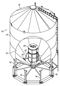
Figure 1 is a perspective view of a hopper bottom grain bin with a portion of
a
sidewall cut away to show the modular aeration assembly of the present
invention installed
within the bin.
Figure 2 is a side elevation view of the bin of Figure 1, with a portion of
the bin
wall cut away to show the modular aeration assembly installed in the bin.
2

CA 02744311 2011-06-23
Figure 3 is a perspective view of the modular aeration assembly of the present

invention.
Figure 4 is a side elevation view of the modular aeration assembly of the
present
invention.
Figure 5 is another side elevation view of the assembly, rotated approximately
900
from Figure 4.
Figure 6 is a top plan view of the modular aeration assembly of the present
invention.
Figure 7 is an enlarged partial perspective view of a pair of adjacent wall
segments,
taken along lines 7-7 of Figure 3, with a portion of the top wall cut away to
show the
internal frames of the wall segments.
Figure 8 is an exploded perspective view of the components of the modular
aeration
assembly of the present invention.
DETAILED DESCRIPTION OF THE PREFERRED EMBODIMENTS
A hopper bottom grain bin is generally designated in the drawings by the
reference
10. The bin 10 includes a sloped floor 12, a sidewall 14, a top 16, and a
plurality of
support legs 18. The bin 10 includes a manhole (not shown in the drawings) in
the floor 12
or in the sidewall 14 for access to the interior of the bin. A door (not
shown) opens and
closes relative to the manhole. It is understood that the size and dimensions
of the bin 10
can vary from those shown in the drawings, including the angular slope of the
floor. The
bin 10 is conventional and does not constitute a part of the present
invention.
The present invention is directed towards a modular aeration assembly or
system 20
which can be installed or retrofit into an existing bin. The aerator assembly
20 generally
includes a cylindrical tower 22 supported above the floor 12 of the bin 10 by
a plurality of
legs 24. Each leg 24 includes a foot 26 pivotally mounted to the lower end of
the leg so as
to accommodate bins having floors with different angled slopes.
The tower 22 is formed by a plurality of curved wall segments 28. Each wall
segment 28 includes an internal frame 30 with inner and outer skins 32, 34.
The frames 30
extending substantially along the full height of the wall segments so as to
provide internal
structural support for the screens 32, 34. The skins 32, 34 are perforated or
louvered so as
3

CA 02744311 2011-06-23
to function as a screen, and are attached to the frame 30 in any convenient
manner, such as
by screws. The frames 30 of adjacent wall segments 28 are bolted together, as
seen in
Figure 7, so as to form the cylindrical tower 22. In the preferred embodiment,
first and
second sets 36, 38 of wall segments 28 are stacked one upon the other so as to
extend the
height of the tower 22. As seen in Figure 8, the opposite lateral sides of
each wall segment
28 are open so that air may flow between adjacent wall segments 28. Similarly,
the upper
ends of the wall segments 28 in the first or lower set 36 are open, as is the
lower ends of the
wall segments 28 in the second or upper set 38, so as to allow for vertical
air flow between
stacked wall segments.
A cap 40 made of two or more pieces is bolted to the top of the tower 22. A
channel jointer 42 is secured to adjacent wall segments 28 so as to cover the
vertical joint
between the wall segments. Similarly, a band 44, formed of one or more pieces,
covers the
joint between the upper and lower sets 36, 38 of wall segments 28.
One of the wall segments 28 includes an air inlet 46. A multi-piece air duct
48
extends between the air inlet 46 and an air source, such as a fan, located
outside the bin 10.
An opening is provided in the sidewall 14 of the bin through which the air
duct 48 extends,
as seen in Figure 2.
All of the components of the aeration assembly 20 are sized so as to pass
through
the manhole of the bin 10. Thus, the components can be separately moved into
the bin 10
through the manhole, and then assembled inside the bin by a single person.
This ability to
retrofit the aeration assembly 20 into an existing bin 10, or to replace a
damaged aeration
system without cutting a large hole in the sidewall 14 of the bin 10 is a
substantial
advantage over the prior art aeration systems, such as The Rocket.
In the assembly process, the components of the aerator assembly 20 are moved
through the manhole into the bin 10. The wall segments 28 are assembled to
form the
tower 22. The air duct 48 is then connected to the tower 22. The legs 24
support the tower
22 above the floor 12 of the bin 10. When the exterior fan is actuated, air
flows through
the air duct 48 and air inlet 46 into the space between the inner and outer
skins 32, 34, and
then passes through the perforations in the skins 32, 34 to facilitate drying
of grain in the
bin 10. The openings between the adjacent stacked wall segments 28 permit
unrestricted
air flow between the segments. The perforations or louvers in the skins or
screens 32, 34
4

CA 02744311 2012-12-31
are designed to prevent material from entering the wall segments 28, while
allowing air to
flow outwardly from the interior of the wall segments 28.
Thus, the aeration assembly 20 of the present invention maintains desirable
temperature and moisture content levels of the stored material within the bin
10 at an
acceptable range so as to prevent spoilage.
It is understood that the embodiments of the invention described above are by
way
of example only and that modifications, substitutions, and additions may be
made to the
embodiments which are within the intended spirit and scope of the invention as
described
above and claimed below.
5

Representative Drawing
A single figure which represents the drawing illustrating the invention.
Administrative Status

For a clearer understanding of the status of the application/patent presented on this page, the site Disclaimer , as well as the definitions for Patent , Administrative Status , Maintenance Fee  and Payment History  should be consulted.

Administrative Status

Title Date
Forecasted Issue Date 2013-12-03
(22) Filed 2011-06-23
Examination Requested 2011-06-23
(41) Open to Public Inspection 2012-02-26
(45) Issued 2013-12-03

Abandonment History

There is no abandonment history.

Maintenance Fee

Last Payment of $347.00 was received on 2024-03-18


 Upcoming maintenance fee amounts

Description Date Amount
Next Payment if standard fee 2025-06-23 $347.00
Next Payment if small entity fee 2025-06-23 $125.00

Note : If the full payment has not been received on or before the date indicated, a further fee may be required which may be one of the following

  • the reinstatement fee;
  • the late payment fee; or
  • additional fee to reverse deemed expiry.

Patent fees are adjusted on the 1st of January every year. The amounts above are the current amounts if received by December 31 of the current year.
Please refer to the CIPO Patent Fees web page to see all current fee amounts.

Payment History

Fee Type Anniversary Year Due Date Amount Paid Paid Date
Request for Examination $800.00 2011-06-23
Application Fee $400.00 2011-06-23
Maintenance Fee - Application - New Act 2 2013-06-25 $100.00 2013-06-21
Final Fee $300.00 2013-09-19
Maintenance Fee - Patent - New Act 3 2014-06-23 $300.00 2014-06-24
Maintenance Fee - Patent - New Act 4 2015-06-23 $100.00 2014-06-24
Maintenance Fee - Patent - New Act 5 2016-06-23 $200.00 2016-06-01
Maintenance Fee - Patent - New Act 6 2017-06-23 $200.00 2017-05-31
Maintenance Fee - Patent - New Act 7 2018-06-26 $200.00 2018-05-31
Maintenance Fee - Patent - New Act 8 2019-06-25 $200.00 2019-05-29
Maintenance Fee - Patent - New Act 9 2020-06-23 $200.00 2020-06-03
Maintenance Fee - Patent - New Act 10 2021-06-23 $255.00 2021-06-02
Maintenance Fee - Patent - New Act 11 2022-06-23 $254.49 2022-05-05
Maintenance Fee - Patent - New Act 12 2023-06-23 $263.14 2023-03-24
Maintenance Fee - Patent - New Act 13 2024-06-25 $347.00 2024-03-18
Owners on Record

Note: Records showing the ownership history in alphabetical order.

Current Owners on Record
WOODHAVEN CAPITAL CORP.
Past Owners on Record
None
Past Owners that do not appear in the "Owners on Record" listing will appear in other documentation within the application.
Documents

To view selected files, please enter reCAPTCHA code :


To view images, click a link in the Document Description column. To download the documents, select one or more checkboxes in the first column and then click the "Download Selected in PDF format (Zip Archive)" or the "Download Selected as Single PDF" button.

List of published and non-published patent-specific documents on the CPD .

If you have any difficulty accessing content, you can call the Client Service Centre at 1-866-997-1936 or send them an e-mail at CIPO Client Service Centre.


Document
Description 
Date
(yyyy-mm-dd) 
Number of pages   Size of Image (KB) 
Abstract 2011-06-23 1 16
Description 2011-06-23 5 204
Claims 2011-06-23 4 113
Drawings 2011-06-23 6 136
Representative Drawing 2011-11-04 1 13
Cover Page 2012-02-17 2 47
Claims 2012-12-31 4 120
Description 2012-12-31 5 204
Cover Page 2013-10-31 2 47
Assignment 2011-06-23 4 98
Prosecution-Amendment 2011-11-23 1 30
Prosecution-Amendment 2012-08-14 3 140
Prosecution-Amendment 2012-12-31 16 512
Fees 2013-06-21 1 163
Correspondence 2013-09-19 2 71
Fees 2014-06-24 1 33