Note: Descriptions are shown in the official language in which they were submitted.
CA 02744537 2013-07-15
72859-364
1
DESCRIPTION
AUTO-INJECTOR APPARATUS
TECHNICAL FIELD
[0001] The present invention relates generally to auto-injector
apparatus for
injecting medicants into a patient.
BACKGROUND ART
[0002] To aid convenience in injecting drugs it is desirable to
simplify the
process by inserting the needle into the delivery site, delivering the drug
and
subsequently sheathing the needle with minimal user input. The prior art has
included a number of auto-injector devices for performing this process. Most
prior art
auto-injectors use glass based syringes or cartridges as the primary packaging
for the
drug or medicant.
[0003] There is a continuing need for improved auto-injector
apparatus that are
simple and reliable in their use and economical in their manufacture.
DISCLOSURE OF THE INVENTION
[0004] In one aspect an auto-injector apparatus includes a flexible
container
= containing a liquid medicant, a needle communicated with the flexible
container, a
housing with the container being received in the housing, a pump disposed in
the
housing and positioned to engage the flexible container and expel the medicant
from
the container through the needle upon relative movement between the pump and
the
container, and a main, drive spring operably associated with the needle to
extend the
= needle from a first needle position wherein the needle is completely
received in the
= housing to the second needle position wherein the needle protrudes from
the housing.
The pump may include a roller.
CA 02744537 2013-07-15
72859-364
la
[0004a] According to another aspect, there is provided an auto-
injector apparatus,
comprising: a flexible container containing a liquid medicament; a needle
communicated with
the container; a housing, the container being received in the housing
comprising a housing
body having a housing interior and an opening, and a housing lid movably
attached to the
housing body, the lid being movable between a closed position closing the
opening and an
open position wherein the housing interior is accessible through the opening;
the housing
further comprising a cocking linkage connecting the lid to the main drive
spring and the
retraction spring so that opening of the lid extends the main drive spring and
the retraction
spring; a pump disposed in the housing and positioned to engage the flexible
container and
expel the medicament from the container through the needle upon relative
movement between
the pump and the container; a main drive spring operably associated with the
needle to extend
the needle from a first needle position wherein the needle is completely
received in the
housing to a second needle position wherein the needle protrudes from the
housing, wherein
the main drive spring is operably associated with the pump to create the
relative movement
between the pump and the flexible container; and a retraction spring operably
associated with
the needle to retract the needle back into the housing after the medicament is
expelled from
the container.
[0005] In another aspect a method of auto-injecting a liquid medicant
into a patient
includes placing a proximal end of an auto-injector apparatus against the
patient's body,
releasing a main spring, driving a needle proximally within the apparatus with
the main drive
spring so that the needle extends out of the proximal end of the apparatus
thereby inserting the
needle in the patient's body, and creating relative motion between a pump and
a flexible
medicant container within the apparatus and thereby forcing the medicant out
of the flexible
container through the needle into the patient's body. The pump may include a
roller.
CA 02744537 2011-05-24
WO 2010/068416 PCT/US2009/065652
2
[0006] In another aspect an auto-injector apparatus includes a flexible
container
containing a liquid medicant, a needle communicated with the container, and a
roller
positioned to engage the flexible container and expel the medicant from the
container
upon relative movement in a displacement direction between the roller and the
container, wherein the flexible container has a width transverse to the
displacement
direction and the width varies along the displacement direction.
[0007] Numerous objects, features, and advantages of the present invention
will
be readily apparent to those skilled in the art upon a reading of the
following
disclosure when taken in conjunction with the accompanying drawings.
BRIEF DESCRIPTION OF THE DRAWINGS
[0008] Figs. 1A-1D comprise a schematic series of figures illustrating the
manufacture and the use of an embodiment of the auto-injector apparatus.
[0009] Fig. 1A illustrates the manufacture of the embodiment of Figs. 1A-
1D.
[0010] Fig. 1B illustrates the embodiment of Figs. 1A-1D ready for use.
[0011] Fig. 1C illustrates an intermediate step in the use of the
embodiment of
Figs. 1A-1D wherein the needle has been uncovered as it would during insertion
into a
patient's body.
[0012] Fig. 1D illustrates a further stage in the use of the embodiment of
Figs.
1A-1D wherein a coil strip spring has rolled over the flexible cartridge to
inject the
medicant.
[0013] Figs. 2A-2G comprise a sequential series of illustrations of the
steps of
usage of an auto-injector apparatus having an injector device using
replaceable
cartridges.
[0014] Fig. 2A shows the device after usage and ready for reloading.
[0015] Fig. 2B shows the device opened for removal of the spent cartridge.
[0016] Fig. 2C shows a replacement cartridge in place within the device.
[0017] Fig. 2D shows the device closed and ready for use.
[0018] Fig. 2E shows the device as it would appear with its proximal end
engaged against the patient's body and with a trigger on its distal end
depressed.
[0019] Fig. 2F illustrates the device with the needle extended from the
device as
it would appear during insertion into the patient's body and injection of the
medicant.
[0020] Fig. 2G shows the device with the needle withdrawn and back in the
same condition as Fig. 2A.
CA 02744537 2011-05-24
WO 2010/068416 PCT/US2009/065652
3
[0021] Fig. 3 is an end view of an embodiment of a replaceable cartridge
for an
auto-injector apparatus.
[0022] Fig. 4 is a right side elevation view of the apparatus of Fig. 3.
[0023] Fig. 5 is a bottom view of the apparatus of Fig. 3.
[0024] Fig. 6 is a top plan view of the apparatus of Fig. 3.
[0025] Fig. 7 is a perspective exploded view of the apparatus of Fig. 3.
[0026] Figs. 8A-8B comprise a sequential series of perspective views
showing
the operation of the apparatus of Fig. 3.
[0027] Fig. 8A shows a perspective view of the apparatus of Fig. 3 ready
for use.
[0028] Fig. 8B shows a perspective view of the apparatus of Fig. 3 wherein
a
needle protection frame is shown in a collapsed position with the needle
extended
therefrom for insertion into the patient and injection of a medicant.
[0029] Figs. 9A-9C comprise a perspective end view of the needle protection
frame and needle hub of the apparatus of Fig. 3 illustrating the manner in
which a
releasable interlock on the needle hub is released upon closure of the lid of
the device.
[0030] Fig. 9A shows the interlock in a locked position prior to closure of
the lid
of the device.
[0031] Fig. 9B illustrates with downward vertical arrows the application of
downward force as would occur by two pins (not shown) of the lid upon closure.
[0032] Fig. 9C shows the collapsed position of the needle protection frame
with
the frame arms sliding through the needle hub.
[0033] Fig. 10 is an exploded perspective view of an embodiment of an auto-
injector apparatus for use with replaceable cartridges.
[0034] Figs. 11, 13, 15, 17, 19, 21 and 23 comprise a sequential series of
perspective views of the apparatus of Fig. 10 showing a series of steps in the
use of the
apparatus.
[0035] Fig. 11 is a perspective view of the apparatus of Fig. 10 in a first
position
prior to opening of the device and prior to loading a cartridge in the device.
[0036] Fig. 12 is a plan view of the apparatus of Fig. 11.
[0037] Fig. 12A-A is an elevation section view of the apparatus of Fig. 12
taken
along line A-A.
[0038] Fig. 12B-B is an elevation section view of the apparatus of Fig. 12
taken
along line B-B.
CA 02744537 2011-05-24
WO 2010/068416 PCT/US2009/065652
4
[0039] Fig. 13 is a perspective view of the apparatus of Fig. 10 in a
second
position wherein the lid has been opened and prior to placement of a cartridge
in the
device.
[0040] Fig. 14 is a plan view of the apparatus of Fig. 13.
[0041] Fig. 14A-A is an elevation section view of the apparatus of Fig. 14
taken
along line A-A.
[0042] Fig. 14B-B is an elevation section view of the apparatus of Fig. 14
taken
along line B-B.
[0043] Fig. 15 is a perspective view of the apparatus of Fig. 10 in a third
position with a cartridge having been placed within the device.
[0044] Fig. 16 is a plan view of the apparatus of Fig. 15.
[0045] Fig. 16A-A is an elevation section view of the apparatus of Fig. 16
taken
along line A-A.
[0046] Fig. 16B-B is an elevation section view of the apparatus of Fig. 16
taken
along line B-B.
[0047] Fig. 17 is a perspective view of the apparatus of Fig. 10 in a
fourth
position with the cartridge in place and with the lid closed.
[0048] Fig. 18 is a plan view of the apparatus of Fig. 17.
[0049] Fig. 18A-A is an elevation section view of the apparatus of Fig. 18
taken
along line A-A.
[0050] Fig. 18B-B is an elevation section view of the apparatus of Fig. 18
taken
along line B-B.
[0051] Fig. 19 is a perspective view of the apparatus of Fig. 10 in a fifth
position
wherein the needle is protruding from the device as it would upon insertion
into a
patient's body, but prior to injection of the medicant into the patient.
[0052] Fig. 20 is a plan view of the apparatus of Fig. 19.
[0053] Fig. 20A-A is an elevation section view of the apparatus of Fig. 20
taken
along line A-A.
[0054] Fig. 20B-B is an elevation section view of the apparatus of Fig. 20
taken
along line B-B.
[0055] Fig. 21 is a perspective view of the apparatus of Fig. 10 in a sixth
position after the medicant has been injected into the patient. It is noted
that Fig. 21
CA 02744537 2011-05-24
WO 2010/068416 PCT/US2009/065652
appears the same as Fig. 19, but the positions of the internal components have
changed.
[0056] Fig. 22 is a plan view of the device of Fig. 21.
[0057] Fig. 22A-A is an elevation section view of the apparatus of Fig. 22
taken
along line A-A.
[0058] Fig. 22B-B is an elevation section view of the apparatus of Fig. 22
taken
along line B-B.
[0059] Fig. 23 is a perspective view of the embodiment of Fig. 10 in a
seventh
position wherein the needle has been withdrawn back into the device.
[0060] Fig. 24 is a plan view of the device of Fig. 23.
[0061] Fig. 24A-A is an elevation section view of the apparatus of Fig. 24
taken
along line A-A.
[0062] Fig. 24B-B is an elevation section view of the apparatus of Fig. 24
taken
along line B-B.
[0063] Fig. 25 is an exploded perspective view of an embodiment of an auto-
injector apparatus designed for a single use.
[0064] Figs. 26A-26H illustrate several variations on the size and shape of
the
flexible drug container. Fig. 26A shows a container of relatively low volume.
Fig. 26B
shows a container of relatively high volume. Fig. 26C shows dual parallel
containers
which allow two drugs to be mixed during injection. Fig. 26D shows dual
containers
in series which allow two drug components to be mixed during injection. Figs.
26E-H
show several variations of a profiled container which affects the rate of
delivery of
medicant.
[0065] Fig. 27 is a schematic perspective view of an embodiment of an
injection
apparatus having a longitudinally fixed roller.
[0066] Fig. 28 is a schematic perspective view of another embodiment of an
injection apparatus having a longitudinally fixed roller.
[0067] Fig. 29 is a schematic perspective view of another embodiment of an
injection apparatus having a longitudinally fixed roller.
[0068] Fig. 30 is a schematic perspective view of another embodiment of an
injection apparatus having a longitudinally fixed roller.
[0069] Figs. 31A and 31B schematically show two positions of an alternative
pump apparatus including an inflatable balloon pump.
CA 02744537 2011-05-24
WO 2010/068416 PCT/US2009/065652
6
[0070] Figs. 32A and 32B schematically show two positions of an alternative
pump apparatus including a pair of magnets on opposite sides of the flexible
container.
[0071] Figs. 33A and 33B schematically show two positions of an alternative
pump apparatus including an electromagnet and a magnetically attracted mass.
[0072] Figs. 34A and 34B schematically show two positions of an alternative
pump apparatus including a source of fluid pressure communicated with the
interior
of the flexible container.
[0073] Fig. 35 is a plan view of a cartridge contained in secondary
packaging.
[0074] Fig. 36 is a side view of the packaging of Fig. 35.
[0075] Fig. 37 is a section view taken along line 37-37 of Fig. 35.
[0076] Fig. 38 is a plan view of a cartridge in another embodiment of
secondary
packaging.
[0077] Fig. 39 shows the packaging of Fig. 38 with a cover peeled back.
[0078] Fig. 40 is a side view of the packaging of Fig. 39.
[0079] Fig. 41 is a plan view of a single use injector device contained in
secondary packaging.
[0080] Fig. 42 is a plan view of a single use device having a transparent
window
covered by a pull strip.
[0081] Fig. 43 shows the device of Fig. 42 after the pull strip has been
pulled to
expose the cartridge through the transparent window.
BEST MODE FOR CARRYING OUT THE INVENTION
The Embodiment of Figs. 1A-1D
[0082] Figs. 1A-1D schematically illustrate one embodiment of an auto-
injector
apparatus.
[0083] Fig. 1A schematically illustrates a step in the assembly of an auto-
injector apparatus 10, a more complete assembly of which is shown in Fig. 1B.
In Fig.
1A, a needle sub-assembly 12 is laid in place upon a flat portion of a
flexible substrate
14.
[0084] The flexible substrate 14 begins as a flat flexible sheet of
material which
may for example be a polymer material and may include a laminated metal layer
as
further described below. A drug containment volume 16, which may also be
referred
to as a flexible container 16, has been formed in a blister manner into the
flat flexible
CA 02744537 2011-05-24
WO 2010/068416 PCT/US2009/065652
7
sheet. Also formed into the sheet are a necked down passage 18, a manifold
portion
20, and a bleed vent 22.
[0085] In Fig. 1B, the substrate 14 has been folded over about a fold line
24 and
the flat portions of the flexible substrate have been sealed together where
they
engage. Also, the necked down passage 18, which may also be referred to as
neck 18,
has been sealed to isolate needle 26 and close the drug containment volume 16
at its
proximal end.
[0086] It is noted that in this description, the term "proximal" is used to
refer to
the end of the apparatus that is closest to or engaged with the patient when
the
apparatus is in use to inject the medicant into the patient's body. Thus the
sharp end
28 of the needle 26 is referred to as the proximal end of needle 26.
Similarly, the
proximal end of the apparatus 10 is indicated at 30. Accordingly the distal
end of the
apparatus 10 is indicated at 32.
[0087] After the substrate 14 has been folded over and the flat portions
and the
neck 18 have been sealed, the drug containment volume 16 is filled with a drug
or
medicant which is placed through the top end 34 of the still open drug
containment
volume 16, then the top end is closed or sealed as indicated at 36 in Fig. 1B.
[0088] Then, the volume of the drug containment volume 16 is compressed
slightly to expel residual air through the bleed feature 22 after which a neck
38 of the
bleed feature 22 is sealed to completely seal the drug containment volume 16.
[0089] Then the back side of the substrate 14 adjacent the drug containment
volume 16 is bonded to an unrolled coil spring strip 40 also sometimes
referred to as a
Tensator spring 40.
[0090] Figs. 1C and 1D schematically illustrate two steps in the use of the
apparatus 10. In Fig. 1C, the actuation of the apparatus 10 has begun, and the
drug
containment volume 16 and needle sub-assembly 12 including needle 26 have
moved
axially forward in a proximal direction forcing the needle 26 to protrude
through the
front 42 of the substrate material 14 with excess material bunching as
indicated at 44
near the root of the needle 26. It will be understood that this step in the
actuation,
and the proximal movement of the drug containment volume and needle sub-
assembly
12 is accomplished by means of an actuating mechanism which is not shown in
Figs.
1A-1D.
CA 02744537 2011-05-24
WO 2010/068416 PCT/US2009/065652
8
[0091] In Fig. 1D, the coil spring strip 40 has been released and has
rolled
forward proximally into its natural coiled state. As the loop of the coil
spring strip 40
rolls forward, it compresses the flexible drug containment volume 16 and
expresses
the drug contained therein through the passage 18 and through the needle 26
into the
patient. The loop may be described as an integral roller portion 41 of the
coil spring
strip 40.
[0092] Several features are provided by the integrated assembly of the
apparatus 10 shown in Figs. 1A-1D.
[0093] The apparatus 10 provides drug containment in the flexible container
defined by the drug containment volume 16 and the surrounding flexible
substrate 14.
[0094] The properties of the material selected for the substrate 14 which
forms
the flexible barrier around the drug containment volume 16 may be selected as
appropriate.
[0095] The folded substrate material about the needle sub-assembly 12 as
seen
in Fig. 1D provides needle sterility until the point of use of the apparatus
10.
[0096] The frangible seal provided at neck 18 provides a dry needle in
storage.
[0097] The bleed feature 22 provides a means of air removal during filling.
[0098] The potential is provided for having two of the drug compartments 16
formed in the substrate 14 which provides a lyophilized powder option, as is
for
example further discussed below with regard to Fig. 26D.
[0099] The apparatus 10 allows for flexible fill volumes by selection of
the size of
the drug containment volume 16 formed in the substrate 14.
[00100] The use of a roller to express the drug from the flexible volume 16
allows
full delivery of contents from the volume 16 through the needle 26.
[00101] The apparatus 10 is compact in size and relatively low in cost.
[00102] The apparatus 10 aids convenience in injecting drugs by simplifying
the
drug injection process by inserting the needle into the delivery site,
delivering the
drug and subsequently sheathing the needle with minimal user input.
[00103] As best seen in Fig. 1A, the needle sub-assembly 12 includes a
needle
hub 46 which as shown in Fig. 1B is structurally connected to the flexible
container 16
via the folded layers of the substrate 14, and is fluidly connected to the
interior of
container 16 via the passage 18 and the manifold portion 20 which communicate
with
CA 02744537 2011-05-24
WO 2010/068416 PCT/US2009/065652
9
an opening (not shown) in the needle hub 46 which in turn communicates with
the
needle 26.
[00104] The needle 26 is attached to the needle hub 46 and extends
proximally
from the needle hub 46. A needle protection frame 48 is connected to the
needle hub
46. The frame 48 includes first and second transversely spaced frame arms 50
and 52
which are supported from the needle hub 46 on opposite sides of the needle 26
and
extend proximally beyond the proximal end 28 of needle 26. Laterally inward
extending supports 54 and 56 are defined on the proximal ends of arms 50 and
52,
respectively, to aid in supporting the folded over substrate 14 as seen in
Fig. 1B. The
arms 50 and 52 hold the front 42 of substrate material 14 away from proximal
end 28
of needle 26.
[00105] When the container 16, needle hub 46 and needle 26 move proximally
forward from the position of Fig. 1B to the position of Fig. 1C relative to
the front 42 of
laminated substrate 14, the frame arms 50 and 52 fold up in an accordion like
manner
as shown in Fig. 1C to allow the relative movement between needle 26 and the
front
42 of the laminate 14. The needle hub 46 and the needle 26 may be described as
being
displaceable relative to the frame 48 in a proximal direction to insert the
needle 26
into a patient.
[00106] Those portions of the laminated material 14 folded over the needle
26
between the arms 50 and 52 as seen in Fig. 1B may be referred to as a flexible
needle
pouch 58 connected to the frame 48 and covering the needle 26 to maintain the
needle
26 in a sterile condition prior to use. As illustrated, the pouch 58 is
collapsible so that
the needle 26 can protrude through the pouch 58 upon proximal displacement of
the
needle hub 46 and needle 26 relative to the frame 48.
[00107] The two sheets of the substrate 14 forming the needle pouch 58 can
be
described as a sheet of flexible material 14 folded at fold 24 into two sheet
portions
joined together along at least two sides as indicated at 60 and 62, the two
sides 60 and
62 extending generally parallel to the needle 26 which may be described as
being
transverse to the fold 24.
[00108] The flexible container 16 may be described as being made up of
first and
second layers of the flexible substrate material 14 joined together to define
a container
space 16 therebetween, the first and second layers of the substrate 14 further
defining
the passages 18 and 20 communicating the container space 16 with the needle
hub 46.
CA 02744537 2011-05-24
WO 2010/068416 PCT/US2009/065652
[00109] As previously noted, the necked down portion 18 of the passage is
temporarily closed to provide a frangible seal temporarily closing the passage
18 to
isolate the needle 26 from medicant in the volume 16. That frangible seal is
formed
by joining portions of the first and second layers of the substrate 14 so that
they are
lightly sealed together across the passage 18 thus blocking the passage 18
until the
pressure within the container 16 is sufficient to break that seal across the
neck down
portion 18 by causing the two layers to peel away from each other.
[00110] The flexible container 16 may also be described as comprising first
and
second layers of the flexible substrate 14, which may be described as a
flexible film 14,
joined together around at least part of a containment perimeter so that the
interior
volume of container 16 is a containment space defined between unjoined
portions of
the first and second layers of the substrate 14. As is apparent in Figs. 1B
and 1C, the
container or containment space 16 is an elongated space having a length 64
extending
generally parallel to a proximal/distal axis 66 of the container 16, and
having a width
68 transverse to and less than the length 64, so that the containment space 16
has
two lengthwise sides 63 and 65 parallel to length 64, a distal side 70 and a
proximal
side 72. The first and second layers of the substrate material 14 are joined
together
on at least the two lengthwise sides 63 and 65 and the distal side 70, and the
two
layers of substrate 14 are further joined together to define the passages 18
and 20
communicating the proximal side 72 of the containment space 16 with the needle
hub
46.
[00111] The coil spring strip 40 may be described as a drive spring 40
having its
integral roller portion 41 which rolls over the flexible container 16 after
the needle 26
is extended to the position shown in Figs. 1C and 1D.
The Embodiment of the Multi-Use Apparatus of Figs. 2-24
[00112] Figs. 2A-2G comprise a sequential series of illustrations showing
the
manner of usage of a multi-use auto-injector apparatus which is generally
designated
by the numeral 100. The apparatus 100 includes a housing 102 having a lid 104
which may be opened as indicated in Figs. 2B and 2C to allow removal and
replacement of a cartridge assembly 106.
The Cartridge Assembly
[00113] The details of construction of the cartridge assembly 106 are seen
in Figs.
3-9. Fig. 3 is a proximal end view of the cartridge assembly 106. Fig. 4 is a
right side
CA 02744537 2011-05-24
WO 2010/068416 PCT/US2009/065652
11
elevation view of the cartridge assembly 106. Fig. 5 is a bottom view of the
cartridge
assembly 106. Fig. 6 is a top plan view of the cartridge assembly 106. Fig. 7
is a
perspective exploded view showing the components of the cartridge assembly
106.
Figs. 8A and 8B show the cartridge assembly in two different operating
positions.
[00114] The cartridge assembly 106 includes a flexible container 108 that
as
schematically illustrated in Fig. 7 includes a liquid medicant 110. As best
seen in Fig.
7, the flexible container 108 comprises first and second layers 112 and 114 of
flexible
film joined together. As shown in Fig. 6, the layers 112 and 114 of film are
joined
together around at least a part of a containment perimeter defined by two
lengthwise
sides 116 and 118, a distal side 120 and a proximal side 122. The interior of
flexible
container 108 may be described as a containment space which is defined between
unjoined portions of the first and second layers 112 and 114. That containment
space
is an elongated space having a length 124 extending generally parallel to a
proximal/distal axis 128 of the container 108, and having a width 130
transverse to
and less than the length 124, so that the containment space within container
108 has
the two lengthwise sides 116 and 118 mentioned plus the distal side 120 and
the
proximal side 122.
[00115] The first and second layers 112 and 114 are joined together along
the two
lengthwise sides 116 and 118 in the areas as indicated at 132 and 134, and
along the
distal side 122 in the area as indicated at 136.
[00116] The upper layer of film 112 has a manifold portion 138 formed
therein as
best seen in Fig. 7. The manifold portion 138 is shaped so as to closely fit
over a distal
portion of a central hub portion 146 of a needle hub 140. The needle hub 140
includes
the central hub portion 146 and upper and lower hub clamps 148 and 150. The
upper
and lower hub clamp portions 148 and 150 have slots such as 176 therein for
receiving
positioning ribs such as 178 of central hub 146 therein. The upper and lower
clamp
portions 148 and 150 are held together by flexible arms such as 180 having
laterally
inward extending protrusions such as 182 which snap fit below ledges such as
184 on
the lower clamp part 150.
[00117] As generally indicated by the dotted line 142 in Fig. 6, a passage
142
communicates the interior of the container 108 with the manifold portion 138
and
thus with the needle hub 140. After the container space within the flexible
container
108 has been filled with the medicant 110, the passage 142 is temporarily
sealed by a
CA 02744537 2011-05-24
WO 2010/068416 PCT/US2009/065652
12
frangible seal 143 which is formed by pressing the first and second layers 112
and 114
of flexible film together and lightly sealing the two together across the
passage 142 so
as to temporarily seal the medicant within the flexible container 108. As is
further
described below, during use of the apparatus 106 a roller will roll across the
flexible
container 108 from its distal end 120 toward its proximal end 122 and the
pressure
within the flexible container 108 will break the seal 143 by causing the
layers 112 and
114 to peel apart within the area of the passage 142 thus allowing the liquid
medicant
to flow from the container 108 through the passage 142 and through the central
hub
portion 146 of needle hub 140 to a needle 144.
[00118] The hub 140 and needle 144 are part of a needle subassembly 152
which
further includes a needle protection frame 154 connected to the needle hub 140
and
including a frame proximal end 156 extending proximally beyond a proximal end
158
of needle 144. As is apparent in viewing Figs. 8A and 8B, the needle hub 140
and
needle 144 are displaceable relative to the frame 154 in a proximal direction
to insert
the needle 144 into a patient.
[00119] The needle protection frame 154 includes first and second
transversely
spaced frame arms 158 and 160 supported from the needle hub 140 on opposite
sides
of the needle 144 and extending proximally beyond the proximal end 158 of
needle
144.
[00120] The frame 154 further includes a front bar 162 made up of upper and
lower front clamp halves 164 and 166, spanning between the proximal ends of
the
frame arms 158 and 160 to protect the proximal end 158 of the needle 144 when
the
needle 144 is in an initial position corresponding to Figs. 4-6 and Fig. 8A.
The upper
and lower front clamp portions 164 and 166 are held together by flexible arms
such as
185 on the upper clamp portion having laterally inward extending protrusion
188. As
best seen in Fig. 3, the front bar clamp portions have recesses defined
therein which
form an opening 168 through the front bar 162 through which the needle 144
passes
when the needle moves proximally relative to the frame 154 to insert the
needle into a
patient. Such proximal movement is illustrated in the position of Fig. 8B
wherein the
needle 144 has passed through the opening 168.
[00121] The upper hub clamp 148 of needle hub 140 includes first and second
cylindrical openings 169 and 171 defined therethrough within which are
slidably
received the cylindrical arms 158 and 160, respectively.
CA 02744537 2011-05-24
WO 2010/068416 PCT/US2009/065652
13
[00122] As best seen in comparing Figs. 8A and 8B, the frame arms 158 and
160
slide through the openings 169 and 171 of needle hub 140 when the needle hub
140
and needle 144 are displaced proximally relative to the frame 154 to insert
the needle
144 into a patient.
[00123] The needle sub-assembly 152 preferably includes a flexible needle
pouch
170 connected to or supported from the frame 154 and covering the needle 144
to
maintain the needle 144 in a sterile condition prior to use. The needle pouch
170 is
collapsible so that the needle 144 can protrude through the pouch 170 upon
proximal
displacement of the needle hub 140 and needle 144 relative to the frame 154 as
illustrated in Fig. 8B. The flexible needle pouch 170 is preferably formed
from two
sheets of flexible film in a manner similar to that described for formation of
the
flexible container 108 from the two sheets 112 and 114. The needle pouch 170
has an
opening 172 at a distal end portion that is similar in size and shape to the
opening or
manifold portion 138 described above, which opening 172 closely fits over a
proximal
portion 174 of the central hub 146. Needle pouch 170 may be formed from a
sheet of
flexible material folded at a fold line 186 into two sheet portions joined
together along
at least two sides transverse to the fold.
[00124] The sheets 112 and 114 are preferably joined together by welding of
the
sheet material. The welding may be accomplished by application of heat, by
application of radio frequency energy, by application of ultrasonic energy, by
friction
welding, or any other suitable welding technique. Alternatively the sheets can
be
joined by solvent bonding or the use of any other suitable adhesive. The
central hub
146 is preferably formed of plastic and is preferably joined to the flexible
container
108 and to the needle pouch 170 by welding of the flexible material to the
central hub
146.
[00125] In any of the embodiments disclosed herein wherein two separate
sheets
are joined together, such as sheets 112 and 114, an equivalent structure may
be
provided by folding a single sheet. Similarly, in any of the embodiments
disclosed
herein wherein a single sheet is folded to form two overlying layers, an
equivalent
structure may be provided by two separate sheets joined together.
[00126] Also, instead of using a needle pouch 170 constructed from two
sheets or
a folded sheet of flexible material, a formed cylindrical rubber or plastic
sheath or
nipple may be used and directly attached to needle hub 140.
CA 02744537 2011-05-24
WO 2010/068416 PCT/US2009/065652
14
[00127] Figs. 9A-9C illustrate the operation of a releasable lock 188
operably
associated with the frame arms 158 and 160 and the needle hub 140. The
releasable
lock 188 can lock the needle protection frame 154 in the locked position as
shown in
Fig. 9A wherein the frame arms 158 and 160 are prevented from sliding distally
relative to the needle hub 140, and an unlocked position as illustrated in
Figs. 9B and
9C, wherein the needle protection frame 154 is allowed to slide distally
relative to the
needle hub 140. The releasable lock 188 includes resilient locking arms 190
and 192
which in their unbiased position as shown in Fig. 9A are received in notches
such as
indicated at 194 in the distal ends of the arms 158 and 160. When the flexible
arms
190 and 192 are received in the notches 194 they prevent the arms 158 and 160
from
sliding distally through the needle hub 140.
[00128] Referring back to the series of figures 2A-2G, when the lid 104 is
returned to a closed position as shown in Fig. 2D a pair of pins (not shown)
on the
underside of the lid 194 engage the flexible arms 190 and 192 and push them
downward as indicated by arrows 196 and 198 in Fig. 9B so as to permit the
arms 158
and 160 to slide distally as shown in Fig. 9C.
[00129] The flexible materials making up the first and second layers 112
and 114
of film which are used to make the flexible container 108 may be selected
based upon
numerous desirable properties for the flexible container 108. For example, the
flexible
container 108 may be constructed from a transparent or translucent material so
that
an extent to which the container 108 is filled with medicant can be observed
by the
user. Also, the materials from which the container 108 is manufactured may be
selected based upon their properties as oxygen and moisture barriers for
protection
and shelf life of the medicant contained in the container 108. One preferred
such
material which will be opaque and will provide very high barrier properties is
a
flexible metallic material which includes an aluminum lamination. Other
metallic
films, layers or foils could also be used. For example a metallic layer could
be vacuum
deposited upon an underlying flexible substrate.
[00130] Numerous examples of possible flexible materials from which the
first
and second layers 112 and 114 of film may be selected are set forth in the
following
Table I along with some approximate properties of these materials as oxygen
and
moisture barriers. In each case the product is described as a lamination of
three
materials.
CA 02744537 2011-05-24
WO 2010/068416 PCT/US2009/065652
Table I
Product Total Oxygen Barrier Moisture Barrier
Thickness (1 ml. volume) (1 ml. volume)
pm (g/m2/day) ppm (cc/m2/day) ppm
PP/201i EVOH/PP 160 1.86 1897 0.2 204
PP/401i EVOH/PP 160 1.93 1969 0.1 102
PP/PET.SIOx/PP 112 0.5 510 0.5 510
PP/231i PCTFE/PP 100 0.23 235 120 122400
PP/5111PCTFE/PP 100 0.11 112 55 56100
PP/PET.SIOx/PP (Super) 112 0.001 1 0.001 1
Lacquer/Aluminum/PP 110 0 0 0 0
[00131] The abbreviations for the products in the first column of Table I
refer to
the following materials:
1. PP is polypropylene.
2. PCTFE is polychlorotrifluoroethylene. Polychlorotrifluoroethylene is a
fluoropolymer that has the best water barrier properties of all suggested
polymers. It is also known under the trademark ALCAR , which is a
product of Honeywell.
3. EVOH is ethylene vinyl alcohol. Ethylene vinyl alcohol is a polymer that
has outstanding oxygen barrier properties, but is prone to moisture
transmission and therefore must be all protected by outer layers.
4. SIOx is silicium oxide. It is a very thin glass layer coated onto a PET
film.
The coating process can be achieved in many different ways.
[00132] The use of a transparent or translucent drug containment film may
be
suitable for drugs that have low dissolved oxygen and low loss of moisture
stability
requirements. It has the advantage that visual inspection of the drug at time
of
manufacture and by the patient before injection is possible. The disadvantage
is
potential susceptibility to ultraviolet radiation. Many of the polymers listed
in Table I
may be obtained in a sufficiently transparent form that the level of the
liquid
medicant in the container can be visualized, although they may not be fully
transparent.
[00133] For drugs that have higher dissolved oxygen and low loss of
moisture
stability requirements, an opaque containment film including a foil layer
within the
CA 02744537 2011-05-24
WO 2010/068416 PCT/US2009/065652
16
film, such as aluminum foil, may be desirable. Such a configuration has the
advantage of less susceptibility to ultraviolet radiation. It has the
disadvantage that
visual inspection of the drug at time of manufacture and by the patient before
injection may not be possible.
External Packaging:
[00134] Another option is to utilize a transparent flexible drug
containment film
which is sealed inside metal foil secondary packaging. This option is suitable
for
drugs that have high dissolved oxygen and low loss of moisture stability
requirements.
It has the advantage that visual inspection of the drug at the time of
manufacture and
by the patient before the injection is possible, and that it is less
susceptible to
ultraviolet. This solution may also be suitable for drugs that have very high
stability
requirements, i.e. if the secondary packaging is sealed under nitrogen or
contains an
oxygen absorbing material. Such an embodiment is shown for example in Figs. 35-
37
wherein the cartridge 106 is shown in place within a foil package 700. The
package
700 is made from a bottom layer 702 and a top layer 704 sealed together around
their
periphery. Top layer 704 is raised as best seen in Figs. 36 and 37 to create
an interior
space 710 for storage of the cartridge 106. Notches 706 and 708 are preformed
in the
package 700 so that it may be torn apart across the width of the package so
that the
cartridge 106 may be removed for use. The package 700 is preferably made of a
metal
foil material which will be impermeable to moisture and air. As noted the
interior 710
of the package may be sealed under nitrogen or contain an oxygen absorbing
material.
The flexible container 108 will be made of transparent material so that when
it is
manufactured, and when it is removed from package 700 for use, it may be
visually
inspected to insure that it is filled with medicant and that the medicant is
clear and
contains no particulates.
[00135] Another form of external packaging is shown in Figs. 38 ¨ 40. In
this
case the cartridge 106 is contained in an opaque package 720, which again is
preferably constructed from a metal foil material such as aluminum. Package
720 is
made from a bottom layer 722 and a top layer 724 joined around their periphery
to
define an interior 726. A window 728 is defined in top layer 724 and is
initially
covered by a peelable strip 730 as shown in Fig. 38. As shown in Figs. 39 and
40 the
strip 730 is peeled back so that the cartridge 106 is visible and can be
removed from
CA 02744537 2011-05-24
WO 2010/068416 PCT/US2009/065652
17
the packaging. Alternatively the entire top layer can be designed to be peeled
back
from the bottom layer.
[00136] Both of the packaging embodiments 700 and 720 just described are
intended for packaging of cartridges for use in multi-use injector devices as
further
described below. Other external packaging arrangements for single use injector
devices are described below with regard to Figs. 41 ¨ 43.
Container Shapes:
[00137] The shape and dimensions of the flexible container 108 may be
selected
based upon various considerations. Several alternatives are shown in Figs. 26A-
26H,
and it will be understood that due to the design flexibility provided by the
use of
molding the flexible film to construct the flexible container 108, any desired
shape can
be readily formed and utilized with the apparatus 100.
[00138] For example, Figs. 26A and 26B show how the volume of liquid
medicant
contained in the flexible container 108 may be readily changed simply by
forming the
container 108 to have a smaller volume. The container 108 in the embodiment of
Fig.
26B has a volume approximately ten times that of the container 108 in the
embodiment of Fig. 26A.
[00139] The embodiment of Fig. 26C includes two flexible containers 108'
and
108" in a parallel relationship, both of which are communicated with the
needle hub
140 through frangible seals such as the frangible seal 143 described above,
thus
permitting the mixing of two liquid drugs during the injection process.
[00140] The embodiment of Fig. 26D includes two flexible containers 108'
and
108" in series. The first container 108' is separated from the second
container 108" by
a first frangible seal 143'. The second container 108" is separated from the
needle hub
140 by a second frangible seal 143". The first container 108' is filled with a
liquid
drug component and the second container 108" is filled with a dry drug
component.
As the roller 210 rolls forward it first pressurizes first container 108' to
burst first
frangible seal 143' so that the liquid component flows into the second
container 108"
and begins to mix with the dry drug component. As the roller 210 continues to
roll
forward the second frangible seal 143" bursts and the mixed liquid and dry
drug
components are expelled through the needle.
CA 02744537 2011-05-24
WO 2010/068416 PCT/US2009/065652
18
[00141] The embodiments of Figs. 26E-26H show profiled containers 108 which
affect the flow rate of delivery of drug from the container 108 as the
mechanism rolls a
roller across the container to squeeze the medicant out of the container.
[00142] In the embodiments of Figs. 26E-26H the roller 210 is positioned to
engage the flexible container 108 and expel the medicant from the container
upon
relative movement between the roller 210 and container 108 in a displacement
direction 211 shown in Fig. 26E. Displacement direction 211 is a longitudinal
direction parallel to the axis 128 of cartridge 106. The roller 210 has a
rotational axis
213 transverse to that displacement direction 211.
[00143] In the embodiment shown in Fig. 26E the flexible container 108 has
a
width 130 transverse to the displacement direction 211, the width 130 varying
along
the displacement direction. The roller 210 first engages the container at a
first
position shown in solid lines and roller 210 moves in the displacement
direction
toward a second position shown in dotted lines. In the embodiments of Figs.
26E and
26G, the width 130 of the container 108 at the second engagement position of
roller
210 shown in dashed lines is less than the width of the container at the first
engagement position, so that the speed of injection of medicant decreases
during
relative movement of the roller 210 between the first and second engagement
positions. This assumes that the roller 210 moves at a constant speed in
direction
211. In the embodiments of Figs. 26E and 26G the width 130 of the container
continuously decreases from the first engagement position to the second
position.
[00144] Conversely, in the embodiment of Fig. 26F, the width of the
container
108 at the second engagement position of the roller 210 shown in dashed lines
is
greater than the width of the container at the first engagement position of
the roller
shown in solid lines, so that a speed of injection of medicant increases
during the
relative movement of the roller 210 between the first and second engagement
positions.
[00145] Finally, as shown in Fig. 26H, the width 130 of the container 108
can
vary in multiple aspects. In the embodiment of Fig. 26H, the width 130 first
decreases, then increases, which provides an alternating injection speed which
first
decreases and then increases.
[00146] It will be appreciated that the profile of the flexible container
can be
designed so as to provide any desired changing injection speed profile.
CA 02744537 2011-05-24
WO 2010/068416 PCT/US2009/065652
19
The Multi-Use Dispensing Device
[00147] The details of construction of those portions of the apparatus 100
other
than the cartridge assembly 106 are best shown in Figs. 10-24. It will be
understood
that the multi-use apparatus of Figs. 10-24 and the single use apparatus of
Fig. 25 are
shown in schematic form in order to illustrate and describe the major internal
working components of the device. Further details of the apparatus 100 are
explained
below with regard to external features of the apparatus 100 which are better
shown in
the series of figures 2A-2G.
[00148] The basic components of the apparatus 100 are most easily
understood
by viewing the exploded view of Fig. 10. The housing 102, which may be
referred to as
a main housing body has a housing interior 202 and an opening 204. The lid 104
is
pivotally attached to the main housing body 102 and is moveable between a
closed
position as shown in Fig. 11 closing the opening 204 and an open position as
shown in
Fig. 13 wherein the housing interior 202 is accessible through the opening
204.
[00149] The apparatus 100 includes a container carriage 206 which is
reciprocably disposed in the housing body 102. As is illustrated and further
described
with regard to Figs. 15 and 16 below, the cartridge assembly 106 including the
flexible
container 108 will be received in the carriage 206 so that the carriage 206,
the
container 108 and the needle 144 are moveable together within the housing 102
between a first carriage position illustrated in Figs. 18, 18A-A and 18B-B and
a
second carriage position illustrated in Figs. 20, 20A-A and 20B-B,
corresponding to
first and second positions of the needle 144, respectively.
[00150] A needle return chassis 208 cooperates with the container carriage
206
and is also reciprocably disposed in the housing 102 to aid in withdrawing the
needle
from its extended position as in Fig. 21 to a retracted safety position as
illustrated in
Figs. 23, 24, 24A-A and 24B-B.
[00151] A roller 210 includes axles such as 212 extending from each end
thereof
which extend through roller tracks or slots 214 and 216 defined in the
container
carriage 206 so as to guide the roller 210 as it rolls in a proximal direction
relative to
the container carriage 206 to expel medicant from the container 108 as will be
further
described below.
[00152] A roller cam 218 has an opening 220 through which the axle 212
extends.
The cam 218 is mounted on the outside of the slot 214. Cam 218 includes a
mounting
CA 02744537 2011-05-24
WO 2010/068416 PCT/US2009/065652
pin 219 which extends through a bore 222 in a spool 224 attached to a main
drive
spring 226. The main drive spring 226 is a coil spring strip which has a first
end 228
fixed to the main housing body 102, and a second end portion 230 which coils
around
the spool 224 as the main drive spring 226 contracts to its relaxed position.
The coil
strip spring 226 may provide a substantially constant spring force, and thus
may be
referred to as a constant force spring. When the main drive spring 226 is
uncoiled or
extended as shown in Fig. 10 it stores potential energy which is utilized to
drive the
container carriage 206 proximally to insert the needle 144 into a patient's
body and to
subsequently drive the roller 210 proximally through the container carriage
206 to roll
over the flexible container 108 to expel the medicant therefrom. The main
drive
spring 226 may be described as being operably associated with the container
carriage
206, and thus with the needle 144 attached to the container 108 carried in the
container carriage 206, so as to extend the needle 144 from a first needle
position as
shown for example in Fig. 18A-A wherein the needle 144 is completely received
in the
housing 102, to a second needle position as shown for example in Fig. 20A-A
wherein
the needle 144 protrudes from the housing 102.
[00153] The main drive spring 226 may also be described as being operably
associated with the roller 210 to roll the roller 210 over the flexible
container 108 after
the needle 144 is extended to its second needle position. As is further
explained below
with regard to Figs. 31-34, the roller 210 may be more generally described as
a pump
210, and other alternative pump structures may be used in other embodiments.
[00154] The roller cam 218 may be further described as a roller interlock
between
the roller 210 and the container carriage 206 to prevent the roller 210 from
rolling
over the flexible container 108 until after the main drive spring 226 moves
the needle
144 to its second needle position.
[00155] As will be further described below with regard to Fig. 14A-A, when
the
lid 104 is opened the roller cam 218 is forced downwardly against the distal
end of the
container carriage 206 by a ramp 232 on the outer body 102. Thus the roller
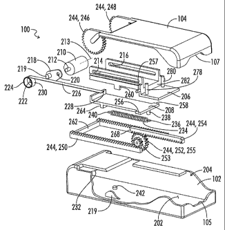
cam 218
will prevent the roller 210 from rolling proximally relative to the container
carriage
206 until after the container carriage 206 has moved proximally to its second
container carriage position as shown for example in Fig. 20A-A.
[00156] A retraction spring 234 has a first end 236 connected to a post 238
on the
needle return chassis 208 and a second end 240 connected to a post 242 fixed
to the
CA 02744537 2011-05-24
WO 2010/068416 PCT/US2009/065652
21
bottom floor of the main housing body 102. As is further explained below the
retraction spring 234 will, at an appropriate time, pull the needle return
chassis 208
and the container carriage 206 and the container 108 and the needle 144 back
in a
distal direction to withdraw the needle 144 after the medicant has been
expelled from
the flexible container 108.
[00157] The apparatus 100 further includes a cocking linkage 244 connecting
the
lid 104 to the main drive spring 226 and the retraction spring 234 so that
opening of
the lid 104 extends the main drive spring 226 and the retraction spring 234.
The
cocking linkage 244 includes a number of components including gears 246 and
248
integrally formed on the distal end of the lid 104, a main drive rack 250, a
drive gear
252, and a spring rack 254. The drive gear 252 includes integrally attached
smaller
gear 253 and larger gear 255. The drive gear 252 is mounted on an axle 257
extending laterally from the container carriage 206. Thus the drive gear 252
moves
laterally with the container carriage 206 within the main housing 102. In the
position
illustrated in Fig. 10, the small gear 253 is engaged with the gear teeth of
the main
drive rack 250, and the larger gear 255 is engaged with the gear teeth of the
spring
rack 254. As is further described below, upon actuation of a trigger 270 the
spring
rack 254 is shifted laterally relative to drive gear 252 out of engagement
with the gear
teeth of larger gear 255.
[00158] Turning now to Figs. 11-24 various operating positions of the
apparatus
100 are illustrated.
[00159] When the apparatus 100 is in the position represented by Figs. 11,
12,
12A-A and 12B-B, the apparatus 100 is in an unprimed state after a previous
injection. For ease of illustration, in views 12A-A and 12B-B no cartridge 106
is
shown within the housing, although there would typically be a spent cartridge
in place
after use of the apparatus 100.
[00160] In this position the needle return chassis 208 has moved distally
until it
abuts a distal end 209 of the housing 102. That movement is accomplished by
the
needle return spring 234. The container carriage 206 is also in its distalmost
position
to which it was carried by engagement of lateral tabs such as 256 and 258 (see
Fig. 10)
defined on needle return chassis 208 with vertical tabs such as 260 extending
downward from container carriage 206. In the position of container carriage
206
shown in Fig. 12A-A the main drive spring 234, which for ease of illustration
is not
CA 02744537 2011-05-24
WO 2010/068416 PCT/US2009/065652
22
shown in Figs. 12A-A or 12B-B, is in a partially extended position to which it
has been
carried by contraction of the return spring 234. As shown in Fig. 12B-B the
roller 210
is in a proximalmost position relative to container carriage 206 to which
position the
roller 210 rolled during the prior actuation of the apparatus 100.
[00161] Moving now from the position of Figs. 11 and 12 to the position of
Figs.
13 and 14, when the user opens the apparatus 100 by lifting the lid 104 from
the body
102 the main drive rack 250 is driven forward or proximally thus forcing the
needle
return chassis 208 forward due to engagement of a cross bar 262 of main drive
rack
250 with a downward extending foot 264 of needle return chassis 208. This
extends
the needle retraction spring 234. A first trigger 266 shown schematically in
Fig. 14A-
A will engage the needle return chassis 208 to prevent the chassis 208 from
moving
rearwardly or distally after the retraction spring 234 has been stretched to
full
extension as shown in Fig. 14A-A.
[00162] Furthermore, in the position of Fig. 14A-A the roller 210 has been
forced
to its distalmost position wherein the roller cam 218 has engaged the ramp 232
and
has moved downward to hold the roller 210 in its distalmost position relative
to the
container carriage 206. When the roller 210 is forced distally this also
serves to
extend the main drive spring 226. These movements have been accomplished by
the
cocking linkage 244 upon opening of the lid 104 in the following manner. As
the lid
104 pivots upwardly away from the main housing body 102 the gears 246 and 248
which are meshed with the teeth of the main drive rack 250 force the main
drive rack
250 to move proximally within the housing 102. As the main drive rack 250
moves in
a proximal direction, it rotates the drive gear 252 which is rotatably mounted
on axle
257 (see Fig. 10) of container carriage 206. As the drive gear 252 rotates,
its larger
gear member is in engagement with the spring rack 254 which drives the spring
rack
254 in the opposite direction from the main drive rack 250. Thus the spring
rack 254
moves in a distal direction and its distal end 268 is engaged with the coil
portion 230
of main drive spring 226 and moves the coil portion 230 distally thus
unwinding and
stretching or extending the main drive spring 226.
[00163] A second trigger 270 schematically illustrated in Fig. 14B-B
prevents the
container carriage 206 from moving forward or proximally.
[00164] With the apparatus 100 in the open position as shown in Fig. 13, a
cartridge assembly 106 can be placed therein as illustrated in Fig. 15.
CA 02744537 2011-05-24
WO 2010/068416 PCT/US2009/065652
23
[00165] Then as shown in Figs. 17 and 18, the lid 104 is closed and the
apparatus
100 is now primed and ready for use. As shown in Figs. 18A-A and 18B-B,
closing the
lid 104 returns the main drive rack 250 to its distalmost position leaving the
needle
return chassis 208 in its cocked or primed position. As previously noted the
needle
return chassis is held in position by first trigger 266.
[00166] Next, a proximal end 272 of the apparatus 100 is held against the
patient's body and second trigger 270 is fired manually to shift the spring
rack 254
sideways thus demeshing the spring rack 254 from the drive gear 252. This
releases
the container carriage 206 so that the container carriage 206 is driven
forward or
proximally by the main drive spring 226. The container carriage 206 carries
with it
the container 108 and the needle hub 140 and needle 144. The needle 144 is
driven
forward or proximally to the position shown in Figs. 19 and 20. During that
movement, the needle protection frame 154 of cartridge assembly 106 has
remained
fixed relative to the housing 102 while the needle hub 140 slides proximally
over the
arms 158 and 160 to a position like that shown in Fig. 8B.
[00167] Thus as the apparatus 100 moves from its position as illustrated by
Figs.
17 and 18 to its position as illustrated by Figs. 19 and 20, the needle hub
140 and
needle protection frame 154 move relatively between their positions as shown
in Fig.
8A to their position as shown in Fig. 8B.
[00168] It is noted that in Fig. 20, the roller 210 still has not moved
forward
within the container carriage 206, because the roller cam 218 has held the
roller 210
in place.
[00169] As the container carriage 206 moves forward the roller cam 218
reaches
the end stop on a ramp 219 (see Fig. 10) on the outer body 102 which forces
the roller
cam 218 upward thus releasing the roller 210 and allowing the roller 210 to
move
proximally along the tracks 214 and 216 thus rolling over the flexible
container 108 to
expel the medicant therefrom. The roller 210 moves from its position as shown
in Fig.
20B-B to its position as shown in Fig. 22B-B. The roller 210 is driven forward
or
proximally relative to the container carriage 206 by the further contraction
of the
main drive spring 226. When the roller 210 reaches its forwardmost position as
shown in Fig. 22B it trips trigger 266 thus releasing the needle return
chassis 208
which is then drawn backward or distally due to contraction of the retraction
spring
234 thus pulling the needle return chassis 208 and the container carriage 206
along
CA 02744537 2011-05-24
WO 2010/068416 PCT/US2009/065652
24
with the cartridge assembly 106 and the needle 144 back to their starting
positions as
shown in Figs. 23 and 24 wherein the needle 144 is once again withdrawn to a
safety
position within the housing 202.
[00170] During that return motion, the main drive spring 226 is partially
extended when the container carriage 206 pulls back the roller 210 from the
position
shown in Fig. 22B-B to the position shown in Fig. 24B-B. The apparatus 100 in
Figs.
23 and 24 is now back in the same position at which it began in Figs. 11 and
12.
[00171] The first trigger 266 may be described as an interlock 266 operably
associated with the needle return chassis 208 and the container carriage 206.
The
interlock 266 releases the needle return chassis 208 after the roller 210
expels the
medicant from the container 108 so that the retraction spring 234 can withdraw
the
needle return chassis 208, the container carriage 206, the container 108 and
the
needle 144 to a safety position wherein the needle 144 is fully received back
in the
housing.
[00172] Thus, the apparatus 100 is in condition to again be opened and have
the
cartridge assembly 106 replaced. Thus the apparatus 100 is a multi-use
apparatus
which can be used any number of times by replacing the cartridge 106 after
use.
[00173] When the cartridge 106 is placed in the container carriage 206 two
openings 274 and 276 (see Fig. 5) in the needle hub 140 receive two posts 278
and 280
(see Fig. 10) extending upward from the container carriage 206. A wall 282 of
container carriage 206 engages a wall 284 (see Fig. 5) of needle hub 140. When
the
cartridge 106 is in place in the apparatus 100 the front bar 162 of cartridge
106 is
closely received in recesses 105 and 107 of housing body 102 and lid 104,
respectively,
as shown in Figs. 15 and 17.
[00174] Then when the container carriage 206 moves forward in later stages
of
operation it immediately moves the needle hub 140 forward while the needle
protection frame 154 remains fixed in place relative to the housing 102.
Interlock Requirements
[00175] The following Table II describes the required interlocks through
one
complete injection cycle for apparatus 100. In Table II the flexible container
108 is
referred to as a sachet.
CA 02744537 2011-05-24
WO 2010/068416
PCT/US2009/065652
Table II
4 ti cr 4 't g:' IF' n cr y t-1 z ts cP ci
0 o ";. o 1;i= 6: 0 % 15-
'z't* ,0
0
Device closed ¨
None None None 1 0 1
0 0 No
Drug delivered
Device Fires, lid snaps
shut. High impact on Device cannot
Device open -
None end stops without fire with lid 1
1 0 0 0 No
Primed
sachet to dampen open
forces.
Device mechanism
damaged hitting end Device cannot
Device primed stops hard if fired. fire without a
None1 1 1 0 0 No
- Closed Mechanism abuse sachet in
possible (biro type position
playing)
Device Fires, lid snaps Device cannot
Device open -
Full shut, Drug delivered fire with lid 1 1 0 1
1 No
Primed
without body contact open
Device fires when not Device will
Device primed
Full in contact with skin, only fire with 1 1 1 1
1 Yes
- Closed
dose lost skin contact
Device closed ¨
Used None None 1 0 1
1 0 No
Drug delivered
Device mechanism
Device cannot
Device open - damaged hitting end
Used fire with lid 1 1 0 1 0
No
Primed stops hard if fired.
open
Used needle fires again
Device primed Used needle fires a Sachet locked
Used1 1 1 1 0 No
- Closed second time after use
[00176] The device trigger 270 must only become unlocked when skin contact
is
made with the needle end of the device 100.
[00177] The 'no sachet' interlock and 'used sachet' interlock could become
one
feature if there was a permanently displaceable component on the container
carriage
208 that interacted with the 'no sachet' interlock.
[00178] The 'lid closed' interlock must be well recessed to prevent
activation by
any means other than the lid 104 being closed in place. This may include
multiple
contact points.
Fixed Roller Embodiments of Figs. 27-30
Fig. 27
CA 02744537 2011-05-24
WO 2010/068416 PCT/US2009/065652
26
[00179] In
the embodiments of Figs. 1-24 described above, during the relative
movement between the roller and the flexible container wherein the medicant is
expelled from the flexible container, the flexible container has been held in
a fixed
position relative to the housing and the roller has moved longitudinally
relative to the
housing to roll over the flexible container to expel the medicant. It is also
possible to
achieve the same relative motion between the roller and the flexible container
by
holding the roller in a fixed position relative to the housing while moving
the flexible
container in a longitudinal direction relative to the housing.
Several such
arrangements are schematically illustrated in Figs. 27-30.
[00180]
Figs. 27 schematically shows an injection apparatus 300 including a
cartridge 302 carried in a container carriage 304. The container carriage 304
functions in a manner similar to the container carriage 206 described above
and is
powered by a main drive spring (not shown) which may be a coil strip main
drive
spring similar to drive spring 226 described above. The carriage 304 and the
drive
spring are received in a housing (not shown) similar to housing 102 described
above.
[00181] The
cartridge 302 includes a needle hub 306 haying a needle 308
extending proximally therefrom. A roller 310 haying first and second coaxial
spaced
roller portions 312 and 314 is longitudinally fixed relative to the housing so
that the
roller 310 rotates relative to the housing but does not move longitudinally
relative to
the housing. The needle 308 extends between the roller portions 312 and 314.
The
roller portions 312 and 314 engage first and second flexible containers 320
and 322
which are communicated at their distal ends with needle hub 306 and thus with
needle 308.
[00182] As
the container carriage 304 begins moving in the direction 316 relative
to the housing and relative to the longitudinally fixed rollers 310, the
needle 308 will
pierce a flexible needle protective sleeve 318 and will be inserted into a
patient's body.
Further movement of the container carriage 304 moves the first and second
flexible
container compartments 320 and 322 past the fixed rollers 312 and 314 so that
the
rollers squeeze the medicant contained in the flexible containers 320 and 322
out
through the needle hub 306 and through the needle 308 into the patient's body.
[00183]
With the embodiment of Fig. 27, as the container carriage 304 moves
forward the needle 308 will continue to be inserted deeper into the patient's
body
while the medicant is simultaneously being expelled through the needle 308
into the
CA 02744537 2011-05-24
WO 2010/068416 PCT/US2009/065652
27
patient's body. Thus some portion of the needle insertion and the drug
injection can
occur simultaneously.
[00184] In all applicable respects other than the geometry of the
arrangement,
the details of construction of the flexible containers 320 and 322, the needle
hub 306
and other components of the apparatus 300 will be similar to those of the
apparatus
100 described in detail above.
Fig. 28
[00185] Fig. 28 schematically illustrates an embodiment somewhat similar to
that of Fig. 27, except in the embodiment of Fig. 28, a secondary carriage is
provided
to first partially insert the needle into the patient's body.
[00186] Thus in Fig. 28 an apparatus 400 is shown including a cartridge 402
carried in a container carriage 404 which is in turn carried in a secondary
carriage
424. The apparatus 400 includes needle hub 406, needle 408, roller 410 with
roller
portions 412 and 414, sheath 418 and flexible containers 420 and 422 all
similar to the
analogous components described above with regard to Fig. 27. The roller
portions 412
and 414 are longitudinally fixed to the secondary carriage 424.
[00187] The secondary carriage 424 carries the container carriage 404 and
accompanying components to initially insert the needle 408 into the patient's
body.
Then further motion of the container carriage 404 relative to the secondary
carriage
424 moves first and second flexible container compartments 420 and 422 past
first
and second roller portions 412 and 414 of roller 410 in the direction 416 to
expel the
medicant from the container portions 420 and 422 and into the patient.
[00188] The motion of container carriage 404 relative to secondary carriage
424,
and the motion of secondary carriage 424 relative to the housing (not shown)
may be
driven by any suitable spring or other power source, such as coil strip
springs like 226
or helical springs like 234.
Fig. 29
[00189] Fig. 29 schematically illustrates another embodiment of the fixed
roller
apparatus which is generally designated by the numeral 500.
[00190] The apparatus 500, similar to the apparatus 300 of Fig. 27,
includes a U-
shape or dual chamber flexible container 502 having first and second container
portions 504 and 506. A bottom portion 508 of the U-shape flexible container
502 may
CA 02744537 2011-05-24
WO 2010/068416 PCT/US2009/065652
28
include a needle hub similar to the needle hub 306 and similar to the needle
hub 140
described above.
[00191] A needle 509 extends proximally from the needle hub 508. Proximal
ends 510 and 512 of the flexible container portions 504 and 506 are attached
to a pull
bar 514. Intermediate portions 516 and 518 of the first and second container
portions
504 and 506 are wrapped around first and second roller portions 520 and 522 of
roller
524. The roller 524 is fixedly attached to the apparatus housing (not shown)
so as to
rotate relative to the housing without moving longitudinally relative to the
housing.
[00192] A main drive spring (not shown) attached to the pull bar 514 pulls
the
pull bar 514 in a distal direction as indicated by arrow 526. This causes the
portions
of the flexible containers 504 and 506 located above the roller 524 to be
pulled distally
while the portions of the flexible containers 504 and 506 located below the
roller 524
move proximally in the direction indicated by arrow 528.
[00193] As those lower portions of the flexible container move proximally,
they
pull forward the needle hub 508 and the attached needle 509 moving them
proximally
so as to insert the needle 509 in the patient and to expel medicant from the
container
portions 504 and 506 through the needle 509 into the patient. The container
portions
504 and 506 may initially be only partially filled so that the initial forward
motion of
needle 509 to insert the needle into the patient's body may occur before the
drug
begins to be expelled through the needle.
[00194] With the embodiment of Fig. 29 the initial proximal movement of the
needle 509 serves to collapse a needle protection sheath 530 and insert the
needle 509
into the patient, and continued proximal movement of the needle 509 will
further
insert the needle 509 into the patient while medicant is simultaneously
expelled from
the flexible container portions 504 and 506 through the needle 509 into the
patient.
Fig. 30
[00195] Fig. 30 schematically illustrates a further embodiment identified
by the
numeral 600 which is similar to the embodiment of Fig. 29 except that it adds
a
secondary carriage 602. Other components are numbered the same as in Fig. 29.
[00196] The secondary carriage 602 provides an initial proximal movement in
direction 528 of the entire flexible container 502 and associated structures
of Fig. 29,
to an initial position which will insert the needle 509 into the patient. Then
a main
drive spring (not shown) initiates the motion of the pull bar 514 in the
direction 526
CA 02744537 2011-05-24
WO 2010/068416 PCT/US2009/065652
29
relative to the secondary carriage 602 and the main housing to further inject
the
needle 509 and expel the medicant from the flexible container 502.
[00197] In general, with regard to all of the embodiments described above,
the
roller can be said to engage its associated flexible container and expel the
medicant
from the container through the needle upon relative movement between the
roller and
the container. In each case the roller has a rotational axis and the relative
movement
between the roller and the container is a relative longitudinal movement in a
longitudinal direction transverse to the rotational axis.
[00198] In some embodiments such as those of Figs. 10-25, the flexible
container
is longitudinally fixed relative to the housing during the injection process,
and the
roller moves longitudinally relative to the container and the housing. In
other
embodiments such as Figs. 27-30, the roller is longitudinally fixed relative
to the
housing during the injection process, and the container moves longitudinally
relative
to the roller and the housing.
Single Use Embodiment of Fig. 25
[00199] Fig. 25 is a schematic perspective exploded view of a single use
embodiment of the auto-injector apparatus. Fig. 25 is similar in many aspects
to Fig.
10, and those components of Fig. 25 identical to the components of Fig. 10 are
identified with the same numerals as used in Fig. 10, and those components
which
have been modified are indicated with a prime suffix. Thus the apparatus of
Fig. 25 is
referred to as the apparatus 100'. The housing includes a main housing body
102' and
a lid 104', however the lid is not designed for repeated opening and closing.
Instead,
the lid 104' is designed to be permanently attached to the main housing body
102' so
that the housing 102', 104' comprises a closed single use housing having an
interior
202 which is inaccessible by a user without damage to the housing.
[00200] The single use apparatus 100' may utilize the same container
carriage
206, roller 210, roller cam 218, main drive spring 226, return chassis 208,
and
retraction spring 234 as were described above with regard to the multi-use
apparatus
100.
[00201] The primary deletions from the apparatus 100 of Fig. 10 include the
cocking linkage 244 and its gears 246 and 248, the main drive rack 250, the
drive gear
252, and the spring rack 254, all of which have been eliminated because there
is no
need for opening of the housing or reloading of the housing with a cartridge.
CA 02744537 2011-05-24
WO 2010/068416 PCT/US2009/065652
[00202] Although not shown in Fig. 25, the single use apparatus 100' will
use the
same cartridge assembly 106 as described above, which will be carried in the
container carriage 206 in the same manner as described above with regard to
the
apparatus 100. The difference is that a single cartridge 102 will be placed
within the
apparatus 100' prior to sealing the lid 104' on the main housing body 102',
and there is
no replacement of that cartridge after use. Thus when the apparatus 100 is
assembled, a cartridge 106 is placed within the cartridge carrier 206. The
roller 210,
roller cam 218, main drive spring 226, container carriage 206, return chassis
208 and
retraction spring 234 are all placed in positions analogous to those shown in
Figs. 17,
18, 18A-A and 18B-B. The triggers 266 and 270 as shown in Fig. 18A-A are in
place.
External Packaging For Single Use Embodiment:
[00203] Figs 41 and 42-43 show two different types of external packaging
that
can be used with the single use injector device 100'.
[00204] In Fig 41 the device 100' is contained in an opaque, preferably
metal foil,
outer package 740 which is constructed like the package 700 described above
with
regard to Fig. 35. Package 740 has notches 742 and 744 which allow the user to
tear
the package open to access the single use device 100'. The device 100' has a
transparent window 746 formed in the front thereof so that the flexible
container 108
of the cartridge 106 contained therein may be viewed to confirm that the
container
108 is filled with medicant prior to use of the device 100'.
[00205] Figs. 42 and 43 show a single use device 760 similar to the device
100' of
Fig. 25, but with a transparent widow 762 formed in the front thereof. The
window
762 is initially blocked in Fig. 42 by an opaque pull strip 764. Prior to use
of the
apparatus 760, the strip 764 is pulled to a second position as shown in Fig.
43, thus
exposing the cartridge 106 to view through the transparent window 762. This
allows
the transparent flexible container 108 of the cartridge 106 to be viewed
through the
window 762 to confirm that the container 108 is full of medicant prior to use
of the
device 760, and to confirm that the medicant is clear and free of
particulates. A
second transparent window and pull strip is preferably provided on the other
side of
the device 760 to allow a see through inspection of the container 108. The
pull strips
preferably are constructed as integral portions of a secondary package around
the
flexible container 108, so that portions of the package are peeled back to
expose the
container 108 when the pull strips are pulled. The secondary container
including the
CA 02744537 2011-05-24
WO 2010/068416 PCT/US2009/065652
31
pull strips should block exposure of the container 108 to light passing
through the
window 762 prior to pulling the pull strips.
Methods of Use
[00206] The methods of use of the apparatus will now be described with
regard to
Figs. 9-24 and the schematic views of Figs. 2A-2G.
[00207] One example of a method of auto-injecting a liquid medicant into a
patient may include:
(a) Placing a proximal end 272 of an auto-injector apparatus 100 or 100'
against
a patient's body 101 - the patient's body 101 is only schematically
illustrated
and may for example be an arm or thigh of the patient such as typically used
as an injection site;
(b) Releasing a main drive spring 226 such as for example by manually
releasing second trigger 270 by depressing the same as indicated by arrow
103 in Fig. 2E;
(c) Driving the needle 144 proximally within the apparatus 100 or 100' with
the
main drive spring 226 so that the needle 144 extends out of the proximal
end 272 of the apparatus 100 or 100' thereby inserting the needle 144 in the
patient's body 101; and
(d) Creating relative motion between roller 210 and flexible container 108
by
rolling the roller 210 over the flexible medicant container 108 within the
apparatus 100 or 100' with the main drive spring 226 after or while the
needle 144 is being inserted in the patient's body 101 and thereby forcing
the medicant out of the medicant container 108 through the needle 144 into
the patient's body 101. During the relative motion between the roller and
the flexible container to force the medicant out of the container, a frangible
seal within the flexible medicant container is broken so that the medicant
can flow from the container to the needle.
[00208] After injecting the medicant into the patient's body, the needle
return
chassis 208 is released to retract the needle 144 back into the apparatus 100
or 100'
with the retraction spring 234 as shown for example in Fig. 2G and in Figs.
23, 24,
24A-A and 24B-B.
[00209] Those steps just described are applicable to both the multi-use
apparatus
100 of Figs. 10-24 and the single use apparatus 100' of Fig. 25.
CA 02744537 2011-05-24
WO 2010/068416 PCT/US2009/065652
32
[00210] For the multi-use apparatus 100 of Figs. 10-24, the apparatus can
further be reloaded by opening the lid 104 of the apparatus 100 to provide
access to
the interior 202. That opening action extends the main drive spring 236 and
the
retraction spring 234 so that the springs 236 and 234 are in position to
repeat the
insertion of the needle and injection of the medicant into the patient. After
opening
the lid, the spent medicant container 106 including its needle 144 is removed
from the
apparatus 100 and a new medicant container and needle assembly 106 are placed
in
the apparatus 100.
[00211] The overall method of operation of the multi-use apparatus 100 of
Figs.
10-24 is schematically illustrated in the seven sequential positions set forth
in Figs.
2A-2G. It is noted that the seven steps represented by Figs. 2A-2G correspond
to the
seven positions of the apparatus 100 illustrated in Figs. 11, 13, 15, 17, 19,
21 and 23,
respectively.
[00212] Thus, in Fig. 2A, Fig. 11, Fig. 12, Fig. 12A-A and Fig. 12B-B, the
apparatus 100 begins in an unprimed state after the previous injection.
[00213] In Fig. 2B, Fig. 13, Fig. 14, Fig. 14A-A and Fig. 14B-B the lid 104
of the
apparatus 100 has been opened. This has reset the main drive spring 226 and
the
retraction spring 234, and has moved roller 210, container carriage 206 and
needle
return chassis 208 to the positions illustrated in Figs. 14A-A and 14B-B.
[00214] In Fig. 2C, Fig. 15, Fig. 16, Fig. 16A-A and Fig. 16B-B a new
cartridge
assembly 106 has been inserted into the apparatus 100.
[00215] In Fig. 2D, Fig. 17, Fig. 18, Fig. 18A-A and Fig. 18B-B the lid 104
has
been closed and the apparatus 100 is primed and ready for use.
[00216] In Fig. 2E, Fig. 19, Fig. 20, Fig. 20A-A and Fig. 20B-B the distal
end 272
of the apparatus 100 is held against the patient's body 101 and the trigger
270 is fired
manually by the user depressing the same with a thumb as indicated by arrow
103.
The trigger 270 shifts the spring rack 254 sideways thus demeshing it from the
drive
gear 252 which releases the container carriage 206 which is then driven
forward by
the main drive spring 226 thus driving the needle 144 into the patient's body
101.
[00217] It is noted that in Fig. 2E the needle 144 is not shown, whereas
the
needle 144 is shown protruding from the housing 102 in Figs. 19 and 20. It
will be
understood that as a result of actuating the trigger 270 as indicated in Fig.
2E the
CA 02744537 2011-05-24
WO 2010/068416 PCT/US2009/065652
33
needle 144 will move forward and will protrude from the apparatus 100 into the
patient's body 101 as shown for example in Fig. 2F.
[00218] Fig. 2F, Fig. 21, Fig. 22, Fig. 22A-A and Fig. 22B-B illustrate the
position
of the various components of the apparatus 100 after the main drive spring 226
has
driven the roller 210 forward to expel the liquid medicant from the flexible
container.
When the roller reaches the end of its travel it trips trigger 266.
[00219] Fig. 2G, Fig. 23, Fig. 24, Fig. 24A-A and Fig. 24B-B illustrate the
position
of the components after trigger 266 has released the needle return chassis 208
so that
the retraction spring 234 draws the needle return chassis 208, the container
carriage
206 and the cartridge assembly 106 back within the housing thus withdrawing
the
needle 144 from the patient.
[00220] In the arrangement just described with reference to Figs. 2A-2G the
proximal end 272 was first pressed against the patient's body to arm the
device, and
then trigger 270 was pressed to fire the device. Alternatively the various
interlocks
between the operating components can be arranged so that the trigger 270 must
first
be pressed to arm the device, and then when distal end 272 is pressed against
the
patient's body the device will automatically fire.
The Alternative Pump Embodiments of Figs. 31-34
Figs. 31A-31B
[00221] As previously noted, the roller 210 may be generally described as a
pump
210 disposed in the housing and positioned to engage the flexible container
108 and
expel the medicant from the container 108 through the needle 144. Figs. 31-34
schematically illustrate alternative pump arrangements which could be
substituted
for the roller pump 210.
[00222] In Figs. 31A and 31B a pump 610 includes an inflatable balloon or
bladder 612 powered by compressed gas or expanding chemical reaction producing
reaction gases from gas source 614 via conduit 616.
[00223] In Fig. 31A the balloon pump 610, 612 is schematically shown in an
uninflated position. In Fig. 31B the pump 610, 612 is schematically shown in
an
inflated position. As the balloon 612 inflates within the housing, it acts
against the
flexible container 108 thus compressing the flexible container 108 to a
compressed
condition as shown in Fig. 31B which expels the medicant from the container
108
through the frangible seal 143 to the needle hub 140. The expanding balloon
612
CA 02744537 2011-05-24
WO 2010/068416 PCT/US2009/065652
34
applies pressure to the flexible container 108 thus squeezing the flexible
container 108
from its original condition shown in Fig. 31A to its compressed position shown
in Fig.
31B.
Figs. 32A-32B
[00224]
Referring now to Figs. 32A-32B, a magnetic pump 620 includes a pair of
magnets 622 and 624. The magnets at one end are pivotally connected at 626. At
the
other end a mechanical blocking device schematically indicated at 628 holds
the
magnets apart so as to define a gap 630 therebetween within which the flexible
container 108 is located. Upon removing the mechanical blocker 628, the magnet
622
moves toward the magnet 624 thus closing the gap 630 and applying pressure to
the
flexible container 108 to collapse the flexible container 108 to a position
such as
schematically illustrated in Fig. 32B, thus expelling the medicant from the
flexible
container 108. The magnetic pump 620 can be described as comprising a pair of
magnets 622 and 624 on opposite sides of the flexible container 108.
Figs. 33A-33B
[00225]
Figs. 33A-33B schematically illustrate an electromagnetic pump 640
which includes an electromagnet 642 and a magnetically attractive mass 644 on
opposite sides of the flexible container 108. The electromagnet 642 may be an
electric
coil type magnet which receives electrical power from battery 646 via wires
648. The
magnetically attractive mass 644 may be a steel plate. In the unactuated
position of
Fig. 33A a gap 650 is defined between electromagnet 642 and steel plate 644,
and the
flexible container 108 is located in the gap 650.
[00226]
When current from battery 646 is applied to the coil of electromagnet 642
the steel plate 644 is drawn toward electromagnet 642 thus closing the gap 650
and
compressing the flexible container 108 to a condition like that schematically
illustrated in Fig. 33B, thus squeezing the medicant out of the flexible
container 108
through the frangible seal 143 to the needle hub 140. The steel plate 644 may
ride on
guideposts 652 and 654 extending upwardly from the electromagnet 642.
Figs. 34A-34B
[00227]
Figs. 34A and 34B schematically illustrate an alternative pump
apparatus 660 wherein the pump comprises construction of the flexible
container 108
from a resilient material so the container can be pressurized to an expanded
position
as shown in Fig. 34A.
When it is desired to expel the medicant from the flexible
CA 02744537 2013-07-15
72859-364
container 108, the frangible seal 143 is breached by any suitable means, thus
allowing
the stretched walls of container 108 to retract to the position of Fig. 34B,
thus forcing
the medicant out of container 108 and past breached seal 143 to needle hub
140.
[00228] Thus it is seen that the apparatus and methods of the
present invention
readily achieve the ends and advantages mentioned as well as those inherent
therein.
While certain preferred embodiments of the invention have been illustrated and
= described for purposes of the present disclosure, numerous changes in the
= arrangement and construction of parts and steps may be made by those
skilled in the
art, which changes are encompassed within the scope of the present
invention as defined by the appended claims.