Note: Descriptions are shown in the official language in which they were submitted.
CA 02744653 2011-05-25
WO 2010/064742 PCT/KR2008/007129
Description
SOUND WAVE RESONANCE GENERATOR
Technical Field
[1] The present invention relates to a sound wave resonance generator that is
placed in
tunnels of roads or railways or around a landing field of airplanes, from
which big
noises are generated, thereby collecting surrounding noises around there,
converting
the collected noises into vibration motions of resonators, converting the
vibration
motions of the resonators into an electrical energy, and making the use of the
electrical
energy as a power source.
Background Art
[2] Generally, electricity has been producing from a number of energy sources
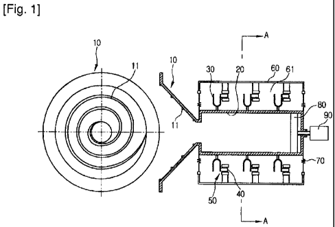
such as
thermal power, nuclear power, hydroelectric power, solar power, wind power,
wave
power, and tide power, which need large- sized power generation equipment.
[3] As much interest in non-polluting energy is increased, recently, many
studies are
made on the technologies for obtaining electricity from energy sources like
solar
power, wind power, wave power, tide power and so on, and additionally, a
variety of
methods have been proposed in view of energy production
[4] By the way, sound waves are a kind of energy that has wavelength, but no
power
generation equipment using the sound waves has been known yet. Big noises are
generated on the subway railways, landing fields, and tunnels, but they just
disappear,
without any utilization as energy.
Disclosure of Invention
Technical Problem
[5] Accordingly, it is an object of the present invention to provide a sound
wave
resonance generator that can produce electricity by using sound waves.
[6] It is another object of the present invention to provide a sound wave
resonance
generator that is placed on underground railways of subways, in tunnels of
surface
streets, and around a landing field of airplane of an airport, from which big
noises are
generated, thereby collecting surrounding noises around there, converting the
collected
noises into vibration, converting the vibration into electricity.
Technical Solution
[7] To achieve the above objects, there is provided a sound wave resonance
generator
including: a sound-collecting tube for collecting surrounding sounds
thereinto; a
resonance tank connected to the rear end of the sound-collecting tube so as to
resonate
the collected sounds; a plurality of resonators attached on the outer
periphery of the
resonance tank in such a manner as to be resonated by the sound waves
transmitted
CA 02744653 2011-05-25
2
WO 2010/064742 PCT/KR2008/007129
through the resonance tank and to generate vibration; an actuator disposed on
one side
end portion of each resonator in a resonance direction in such a manner as to
be re-
ciprocally moved by the resonance of each resonator and having a plurality of
magnets
arranged in turn in such a manner as to have different polarities from each
other; and a
stator having coils mounted over and below the actuator so as to induce an
elec-
tromotive force by the reciprocal movements of the actuator and to generate
and output
power therefrom.
[8] According to the present invention, the sound wave resonance generator
further
includes: an outer casing spaced apart from the resonance tank by a
predetermined
distance in such a manner as to be opened on the both end surfaces thereof,
thereby
forming a resonance chamber where the resonators, the actuators, and the
stators are
disposed, supporting the resonance tank thereagainst, and fixedly mounting the
stators
thereon; a plurality of diaphragms disposed between each of the opened both
end
surfaces of the outer casing and the resonance tank in such a manner as to
close the
resonance chamber where the resonators are disposed and to allow air to flow
during
the resonance of the resonators; a resonance-adjusting plate disposed at the
inside of
the resonance tank so as to adjust the volume of the inside area of the
resonance tank;
and a resonance adjustor mounted at the rear end portion of the resonance tank
in such
a manner as to be exposed to the outside, thereby adjusting the forward and
backward
movements of the resonance-adjusting plate.
[9] According to the present invention, the sound-collecting tube is a horn-
like tube that
becomes large toward the outside end portion thereof and small toward the
inside end
portion thereof connected to the resonance tank and has a spiral protruding
part formed
along the inside wall thereof, thereby taking a cochlea-like shape.
[10] According to the present invention, the stator is configured to output an
elec-
tromotive force induced therefrom to the outside, such that the outputted
electromotive
force is passed through a voltage- stabilizing circuit and a dual voltage
circuit and is
then charged to a charging battery or is supplied to driving power for a load
(for
example, an illuminating light).
[11] According to the present invention, the sound wave resonance generator is
placed on
the lateral walls around underground railways of subways, in the landing field
of
airports, and in tunnels of surface streets, thereby collecting surrounding
noises,
producing electricity from the collected noises, and driving a load by using
the
electricity. If the outside sounds are collected to the sound-collecting tube,
the sound
waves are transmitted to the interior of the resonance tank, and then, the
resonance
tank is resonated by the collected sound waves. Next, the resonators attached
on the
outer peripheral wall of the resonance tank become vibrated.
[12] Each of the resonators is vibrated on the end portion thereof by the
sound waves
CA 02744653 2011-05-25
3
WO 2010/064742 PCT/KR2008/007129
transmitted through the resonance tank. At this time, the actuator attached on
one side
end portion of each resonator is vibrated horizontally in accordance with the
vibration
of each resonator. Since the actuator has the plurality of magnets and the
stator has the
coils mounted over and below the actuator, if the actuator is vibrated
horizontally, the
electromotive force is induced to the stator composed of the coils by the
formation of
the magnetic field from the actuator, thereby generating power therefrom. The
power is
charged and boosted by using an external power device so as to be used as the
driving
power for a load.
[13] The resonance chamber formed by the outer casing is closed by means of
the
diaphragms formed at the both ends thereof, such that the air generated upon
the
resonance of the resonators can flow, the variation of air pressure can be
prevented,
and stable resonance can be achieved. The resonance tank has the resonance-
adjusting
plate mounted at the inside thereof so as to adjust the volume of the inside
area of the
resonance tank, which means a standing wave ratio, i.e., a maximum resonance
point is
adjusted. Since the resonance-adjusting plate is forwardly and backwardly
moved by
the manipulation of the resonance adjustor mounted at the outside thereof, the
volume
of the inside area of the resonance tank can be adjusted appropriately.
Advantageous Effects
[14] According to the present invention, there is provided the sound wave
resonance
generator that collects surrounding sounds, converts the collected sounds into
vibration
through the resonators, allows the actuators to be horizontally reciprocated
by the
vibration of the resonators, and induces the electromotive force to the
stators composed
of coils, thereby producing electricity, such that the sound wave resonance
generator is
located on a place where big noises are generated so as to convert the noises
into
electrical power used as load-driving power. Therefore, the sound wave
resonance
generator is installed on the place where big noises are generated, for
example, on the
underground railways of subways, in the landing field of airport, and in
tunnels of
surface streets, such that the electricity produced therefrom can be used as
the driving
power for illuminating lights.
Brief Description of the Drawings
[15] FIG. 1 is a sectional view showing a configuration of a sound wave
resonance
generator according to the present invention.
[16] FIGS. 2 and 3 are sectional and perspective views showing the actuator
and stator of
the sound wave resonance generator according to the present invention.
[17] FIG.4 is a horizontal sectional view showing the sound wave resonance
generator
according to the present invention.
Mode for the Invention
CA 02744653 2011-05-25
4
WO 2010/064742 PCT/KR2008/007129
[18] Hereinafter, an explanation on a sound wave resonance generator according
to a
preferred embodiment of the present invention will be given with reference to
the
attached drawings.
[19] FIG. 1 is a sectional view showing a configuration of a sound wave
resonance
generator according to the present invention.
[20] According to the present invention, there is provided a sound wave
resonance
generator including: a sound-collecting tube 10 for collecting surrounding
sounds
thereinto; a resonance tank 20 connected to the rear end of the sound-
collecting tube 10
so as to resonate the collected sounds; a plurality of resonators 30 attached
on the outer
periphery of the resonance tank 20 in such a manner as to be resonated by the
sound
waves transmitted through the resonance tank 20 and to generate vibration
therefrom;
an actuator 40 disposed on one side end portion of each resonator 30 in a
resonance
direction in such a manner as to be reciprocally moved by the resonance of
each
resonator 30 and having a plurality of magnets arranged in turn in such a
manner as to
have different polarities from each other; and a stator 50 having coils
mounted over
and below the actuator 40 so as to induce an electromotive force by the
reciprocal
movements of the actuator 40 and to generate and output power therefrom.
[21] According to the present invention, the sound wave resonance generator
further
includes: an outer casing 60 spaced apart from the resonance tank 20 by a pre-
determined distance in such a manner as to be opened on the both end surfaces
thereof,
thereby forming a resonance chamber 6 1 where the resonators 30, the actuators
40, and
the stators 50 are disposed, supporting the resonance tank 20 thereagainst,
and fixedly
mounting the stators 50 thereon; a plurality of diaphragms 70 disposed between
each
of the opened both end surfaces of the outer casing 60 and the resonance tank
20 in
such a manner as to close the resonance chamber 6 1 where the resonators 30
are
disposed and to allow air to flow during the resonance of the resonators 30; a
resonance-adjusting plate 80 disposed at the inside of the resonance tank 20
so as to
adjust the volume of the inside area of the resonance tank 20; and a resonance
adjustor
90 mounted at the rear end portion of the resonance tank 20 in such a manner
as to be
exposed to the outside, thereby adjusting the forward and backward movements
of the
resonance-adjusting plate 80.
[22] FIGS. 2 and 3 are sectional and perspective views showing the actuator
and stator of
the sound wave resonance generator according to the present invention. Each of
the
stators 50 has the coils mounted over and below the actuator 40 corresponding
thereto
at the inside of a circular bracket thereof in such a manner as to permit the
elec-
tromotive force to be generated and outputted from the coils by the reciprocal
movement of the actuator 40, and the bracket of the stator 50 is fixedly
mounted on the
outer casing 60. Each of the actuators 40 has a plurality of magnets arranged
in turn in
CA 02744653 2011-05-25
WO 2010/064742 PCT/KR2008/007129
such a manner as to have different polarities from each other.
[23] FIG.4 is a horizontal sectional view showing the sound wave resonance
generator
according to the present invention. As shown, the plurality of resonators 30
are
disposed on the outer periphery of the resonance tank 20, and according to the
preferred embodiment of the present invention, the resonators 30 are disposed
in four
directions along the outer periphery of the resonance tank 20. Each of the
resonators 30
has the actuator 40, and the stator 50 is mounted correspondingly to each
actuator 40.
[24] The sound-collecting tube 10 is a horn-like tube that becomes large
toward the
outside end portion thereof and small toward the inside end portion thereof
connected
to the resonance tank 20 and has a spiral protruding part 11 formed along the
inside
wall thereof, thereby taking a cochlea-like shape.
[25] Even though not in the drawing, also, a power device is further provided
to stabilize
the output of the stator 50 and to supply the output as driving power for a
load.
[26] The output of the stator 50 through the power device is passed through a
rectifier
circuit, a voltage-stabilizing circuit, and a dual voltage circuit and is then
charged to a
charging battery or is then supplied to driving power for a load (for example,
an il-
luminating light).
[27] According to the present invention, the sound wave resonance generator is
placed on
the lateral walls around underground railways of subways, in the landing field
of
airports, and in tunnels of surface streets, thereby collecting surrounding
noises,
producing electricity from the collected noises, and driving a load by using
the
electricity. If the outside sounds are collected to the sound-collecting tube
10, the
sound waves are transmitted to the interior of the resonance tank 20, and
then, the
resonance tank 20 is resonated by the collected sound waves. Next, the
resonators 30
attached on the outer peripheral wall of the resonance tank 20 become
vibrated. As
shown, the sound-collecting tube 10 has a cochlea-like shape in such a manner
as to
form the spiral protruding part 11 along the inside wall thereof, thereby
serving to
collect the sound waves generated from the outside to the resonance tank 20
via the
spiral protruding part 11. Each of the resonators 30 is vibrated on the end
portion
thereof by the sound waves transmitted through the resonance tank 20. Each of
the
resonators 30 is formed of a steel plate having an appropriately horseshoe
magnet- like shape. At this time, the actuator 40 attached on one side end
portion of
each resonator 30 is vibrated horizontally in accordance with the vibration of
the
resonator 30 corresponding thereto.
[28] As shown in FIG.2, the actuator 40 has the plurality of magnets, and the
stator 50 has
the coils mounted over and below the actuator 40. When the actuator 40 is
vibrated
horizontally, the electromotive force is induced to the stator 50 composed of
the coils
by the formation of the magnetic field from the actuator 40, thereby
generating power
CA 02744653 2011-05-25
6
WO 2010/064742 PCT/KR2008/007129
therefrom. The power is charged and boosted by using an external power device
so as
to be used as the driving power for a load.
[29] The resonance chamber 6 1 formed by the outer casing 60 is closed by
means of the
diaphragms 70 formed at the both ends thereof, such that the air generated
upon the
resonance of the resonators 30 can flow, the variation of air pressure can be
prevented,
and stable resonance can be achieved.
[30] According to the present invention, therefore, the sound wave resonance
generator
can collect the noises generated on the underground railways of the subways,
on the
landing field of airports, and in the tunnels of surface streets by means of
the sound-
collecting tube 10, vibrate the actuators 40 by the collected sounds by means
of the
resonance tank 20 and the resonators 30, and convert the vibration into an
electrical
energy by means of the stators 40.