Note: Descriptions are shown in the official language in which they were submitted.
CA 02745062 2013-12-11
- 1 -
METHODS AND APPARATUS FOR ESTIMATING THE INSTANTANEOUS
ROTATIONAL SPEED OF A BOTTOM HOLE ASSEMBLY
FIELD OF THE INVENTION
The present invention relates to a method of damping stick-slip oscillations
in
a drill string, to a method of drilling a borehole, to a method of estimating
the
instantaneous rotational speed of a bottom hole assembly, to a drilling
mechanism for
use in drilling a borehole, to an electronic controller for use with a
drilling
mechanism, and to a method of upgrading a drilling mechanism on a drilling
rig.
BACKGROUND TO THE INVENTION
Drilling an oil and/or gas well involves creation of a borehole of
considerable
length, often up to several kilometres vertically and/or horizontally by the
time
production begins. A drillstring comprises a drill bit at its lower end and
lengths of
drill pipe that are screwed together. The whole drillstring is turned by a
drilling
mechanism at the surface, which in turn rotates the bit to extend the
borehole. The
drilling mechanism is typically a top drive or rotary table, each of which is
essentially
a heavy flywheel connected to the top of the drillstring.
The drillstring is an extremely slender structure relative to the length of
the
borehole, and during drilling the string is twisted several turns because of
torque-on-
bit between about 500 and 10,000Nm. The drillstring also displays a
complicated
dynamic behaviour comprising axial, lateral and torsional vibrations.
Simultaneous
CA 02745062 2013-12-11
¨ 2 ¨
measurements of drilling rotation at the surface and at the bit have revealed
that the
drillstring often behaves as a torsional pendulum i.e. the top of the
drillstring rotates
with a constant angular velocity, whereas the drill bit performs a rotation
with
varying angular velocity comprising a constant part and a superimposed
torsional
vibration. In extreme cases, the torsional part becomes so large that the bit
periodically comes to a complete standstill, during which the drillstring is
torqued-up
until the bit suddenly rotates again at an angular velocity that is much
higher than the
angular velocity measured at the surface. This phenomenon is known as stick-
slip.
Stick-slip has been studied for more than two decades and it is recognized as
a major
source of problems, such as excessive bit wear, premature tool failures and
poor
drilling rate. One reason for this is the high peak speeds occurring during in
the slip
phase. The high rotation speeds in turn lead to secondary effects like extreme
axial
and lateral accelerations and forces.
A large number of papers and articles have addressed the stick-slip problem.
Many
papers focus on detecting stick-slip motion and on controlling the
oscillations by
operational means, such as adding friction reducers to the mud, changing the
rotation
speed or the weight on bit. Even though these remedies sometimes help, they
are
either insufficient or they represent a high extra costs.
A few papers also recommend applying smart control of the top drive to
dampen and prevent stick-slip oscillations. In IADC/SPE 18049 by Halsey, et
aL,
entitled "Torque Feedback used to cure Slip-Stick Motion", SPE Annual
Technical
Conference and Exhibition, 2-5 October 1988, Houston. Texas, it was
demonstrated
that torque feed-back from a dedicated string torque sensor could effectively
cure
stick-slip oscillations by adjusting the speed in response to the measured
torque
variations. In Jansen J. D. et al. "Active Damping of Self-Excited Torsional
CA 02745062 2013-12-11
- 3 -
Vibrations in Oil Well Drillstrings", 1995, Journal of Sound and Vibrations,
179(4),
647-668, it was suggested that the drawback of this approach is the need for a
new
and direct measurement of the string torque, which is not already available.
US 5 117
926 disclosed that measurement as another type of feedback, based on the motor
current (torque) and the speed. This system has been commercially available
for
many years under the trade mark SOFT TORQUE . The main disadvantage of this
system is that it is a cascade control system using a torque feedback in
series with the
stiff speed controller. This increases the risk of instabilities at
frequencies higher than
the stick-slip frequency.
IADC/SPE 28324 entitled "Application of High Sampling Rate Downhole
Measurements for Analysis and Cure of Stick-Slip in Drilling" discloses
control of a
drilling process using driving equipment that includes a PID, a motor, a gear
box and
rotary table. The PID tries to maintain the desired rotary speed of the drill
string and
it is suggested that the PID can be adjusted to prevent stick-slip. However, a
simulation result shows poor damping of stick-slip oscillations and it is
concluded in
the paper that PID is too simple a servo-control system to prevent stick-slip.
Our co-pending patent application PCT/0B2008/051144 discloses a method
for damping stick-slip oscillations, the maximum damping taking place at or
near a
first or fundamental (i.e. lowest frequency) stick-slip oscillation mode. In
developing
the method we have identified a further problem to be addressed when the drill
string
is extremely long (greater than about 5km) and the fundamental stick-slip
period
exceeds about 5 or 6s. Even though the method of our previous patent
application is
able to cure the fundamental stick-slip oscillation mode in such strings, as
soon as
these oscillations are dampened, the second natural mode tends to become
unstable
and grow in amplitude until full stick-slip is developed at the higher
frequency. In
certain simulations we have found that this second mode has a natural
frequency
which is approximately three times higher than the fundamental stick-slip
frequency.
CA 02745062 2013-12-11
- 4 -
The higher order stick-slip oscillations are characterised by short period and
large
amplitude cyclic variations of the drive torque. Simulations show that the bit
rotation
speed also in this case varies between zero and peak speeds exceeding twice
the mean
speed.
We have also found through other simulations that the method employed by
the aforementioned SOFT TORQUES system suffers from the same problem.
Neither method is able to inhibit both the first and second mode stick-slip
oscillations.
SUMMARY OF THE INVENTION
Aspects of the present invention are based on the insight that a PI or PID
controller can in fact be used to obtain significant damping of stick-slip
oscillations
by the drilling mechanism. In particular we have realised that a PI or PID
controller
can be tuned to ensure efficient damping torsional wave energy at and/or near
the
fundamental mode of stick-slip frequency. A further insight on which certain
embodiments are based is that both the fundamental and one or more higher mode
(e.g. second natural mode and greater) oscillation can also be damped by
reducing the
effective inertia of the drilling mechanism, which may be achieved in several
different ways. One way is by further adjustment of the PI or PID controller.
Another
way is by changing the drilling mechanism to a higher gear. In some
embodiments
the fundamental and one or more higher mode may be damped selectively either
by a
computer decision in advance (e.g. using predictions based on string
geometry),In
other embodiments the damping may be selectively activated by monitoring the
period of the fundamental mode and applying the method when the period of the
fundamental exceeds a certain threshold.
CA 02745062 2013-12-11
- 5 -
In contrast to some earlier systems the present invention is passive the sense
that neither string torque nor drive torque is needed in a feed-back loop.
Accordingly
damping can be achieved without the need for additional sensors to measure
string
torque, that otherwise increases complexity and cost.
Other aspects of the invention are based upon the insight that it is possible
to
estimate the instantaneous rotational speed of the bit (ignoring any
contribution from
an optional mud motor) and to make this information available to other control
processes on the rig and/or to the driller via a console. By repeating the
method, a
substantially real-time estimation of bit speed can be provided. Provision of
this data
may help a driller and/or other automated drilling control process determine
whether
the PI tuning aspect of the invention would improve drilling performance e.g.
by
reducing stick/slip.
According to certain aspects of the present invention there is provided a
method of damping stick-slip oscillations in a drill string, which method
comprises
the steps of:
(a) damping said stick-slip oscillations using a drilling mechanism
at the
top of said drill string; and
(b) controlling the speed of
rotation of said drilling mechanism using a PI
controller;
characterised by the step of
(c) tuning said PI
controller so that said drilling mechanism absorbs most
torsional energy from said drill string at a frequency that is at or near a
frequency of
said stick-slip oscillations, and/or at or near a fundamental frequency and at
least one
higher frequency mode of said stick-slip oscillations. The drilling mechanism
may
comprise a top drive or a rotary table for example. It is to be noted that the
PI
CA 02745062 2013-12-11
- 6 -
controller may be tuned once (for example upon encountering stick-slip for the
first
time, or in advance of drilling) and upon subsequent occurrences of stick-slip
the PI
controller may be used again without being re-tuned. Another possibility is
for the PI
controller to be re-tuned each time stick-slip is encountered, or even
periodically
during a stick-slip phase of drilling. In one embodiment, the PI controller is
tuned
before it is used to control the drilling mechanism to damp stick-slip
oscillations. For
example, the controller may be tuned upon encountering stick-slip oscillations
or it
may be performed periodically during drilling of the borehole as the drill
string
length increases. One possibility is for the tuning to take place as each 30m
section of
drill pipe is added to the drill string.
In certain embodiments, the PI controller may adjusted to damp both a
fundamental frequency and one or more higher mode stick-slip oscillations; the
options for such tuning include: tuning in advance of drilling (for example on
the
basis of predictions using string geometry, or simply as a precaution against
higher
mode oscillations whether they are expected or not), tuning on encountering a
fundamental mode (whether or not higher modes are expected) or tuning on
encountering higher mode stick-slip oscillations.
In some embodiments said stick-slip oscillations comprise torsional waves
propagating along said drill string, and step (c) comprises adjusting an I-
term of said
PI controller to be dependent on an approximate period of said fundamental
frequency of said stick slip oscillations and on an effective inertia of said
drilling
mechanism, whereby said drilling mechanism has a frequency dependent
reflection
coefficient of said torsional waves, which reflection coefficient is
substantially at a
minimum at or near said fundamental frequency of stick-slip oscillations. It
is to be
noted that it is not essential for the peak absorption frequency of the
drilling
mechanism to match exactly the fundamental frequency of the stick-slip
oscillations.
Due to the way the PI controller is tuned, the drilling mechanism has a
bandwidth of
CA 02745062 2013-12-11
- 7 -
frequency absorption that is of a sufficient width (e.g. ¨0.4Hz) and magnitude
(e.g.
less than 85% reflection) so that damping is still effective even if the two
frequencies
are not exactly matched. This represents a significant advantage of the
method.
Typically, the fundamental frequency of stick-slip oscillations encountered in
practice lies in the range 0.1Hz (period 10s) to 0.5Hz (period 2s) and the
peak
absorption frequency caused by the PI controller may be within 50% of the
fundamental frequency.
In some embodiments the lowest point of the frequency-reflection coefficient
curve has a value between about 50% (0.5) and 90% (0.9). It has been found
that
reflection coefficients any higher than about 90% can make the drilling
mechanism
too "stiff" and reduce the chance of successfully damping the stick-slip
oscillations.
On the other hand, it has been found that a reflection coefficient of any
lower than
about 50% makes the drilling mechanism too "soft" and drilling performance can
be
impaired since the drilling mechanism responds to much smaller changes in
drill
string torque resulting in high speed variations.
The absorption bandwidth is inversely proportional to the effective inertia
Jof
the drilling mechanism. Therefore as the effective inertia of a drilling
mechanism
increases, it is preferable although not essential, that the approximate stick-
slip period
is estimated or measured more accurately to ensure that the frequency of
greatest
damping is real stick-slip frequency.
In some embodiments the method further comprises the step of adjusting said
I-term according to / = 6`)2f where co, is an approximate or estimated angular
frequency of said stick-slip oscillations and J is the effective inertia of
said drilling
mechanism. cos could of course be expressed in terms of other parameters in
this
formula, such as the period or frequency.
CA 02745062 2013-12-11
- 8 -
In certain embodiments, said effective inertia comprises the total mechanical
inertia of said drilling mechanism at an output shaft thereof. This has been
found
useful for damping predominantly only a fundamental mode of stick-slip
oscillation,
although higher modes are damped to some extent.
In other embodiments, the method further comprises the step of reducing an
effective inertia of said drilling mechanism, whereby a damping effect of said
drilling
mechanism is increased for frequencies above said fundamental frequency. This
is a
significant optional step of the method that enables one or more higher mode
oscillations to be damped (and in some embodiments cured altogether) at the
same
time as damping the fundamental mode. This possibility is particularly
important for
long drill strings (typically over about 5km in length), where higher mode
oscillations
are likely to be problematic. Reduction of effective inertia may be applied
continuously (whether or not higher mode stick-slip is expected) or
selectively either
upon detection of a fundamental mode of period greater than a certain
threshold (e.g.
five seconds), or in response to detection of one or more higher mode whilst
drilling.
Furthermore, the quantity of inertia reduction may be adjusted to change the
amount
of damping at higher frequencies.
In some embodiments the step of reducing said effective inertia comprises the
step of tuning said PI controller with an additional torque term that is
proportional to
the angular acceleration of said drilling mechanism. Since the angular
acceleration is
readily derived from the angular speed of the drilling mechanism, this makes
the
method very easy to implement in computer operated speed controller (for
example a
controller implemented in a PLC).
CA 02745062 2013-12-11
- 9 -
In certain aspects, the method further comprises the step of multiplying said
angular acceleration by a compensation inertia (J), which compensation inertia
(Jc)
is adjustable so as to control the amount of the reduction of the effective
inertia of
said drilling mechanism. The compensation inertia may be a relatively static
value
(e.g. set by a driller via a console) or a dynamic value (e.g. adjusted in
real time
according to drilling conditions). Typically the compensation inertia (Jc) may
be
adjusted so as to reduce said effective inertia by between 0 and 80%.
In some embodiments the method further comprises the step of adjusting said
2
I-term of said PI controller according to I = J , where cos is an
approximate or
estimated angular frequency of said stick-slip oscillations and .1 is the
reduced
effective inertia value of said drilling mechanism.
In certain embodiments said drilling mechanism has a torsional energy
absorption bandwidth for stick-slip oscillations, the size of said bandwidth
obtainable
from its full width half maximum, whereby upon reducing the effective inertia
of said
drilling mechanism the size of said full width half maximum is greater. Use of
the
FWHM provides a convenient way to compare different absorption bandwidths.
In some embodiments said drilling mechanism has a frequency dependent
damping curve having a point of maximum damping, the method further comprising
the step of shifting said point of maximum damping to higher frequencies
whereby
the damping effect of said drilling mechanism on at least some higher
frequencies is
increased and damping of said fundamental frequency is reduced. This is
referred to
herein as de-tuning, and optionally, is performed if higher mode stick-slip
oscillations
are not reduced or cured by the inertia compensation method.
CA 02745062 2013-12-11
- 10 -
In some aspects, said step of shifting comprises determining an I-term of said
/ = co,2J
PI controller as , in which a period value cos is greater than said
approximate period of said fundamental frequency, whereby said frequency
dependent damping curve is shifted toward higher frequencies and damping of at
least one higher mode of oscillation is increased above the amount of damping
obtainable when using said approximate period to determine said I-term. The
period
value may be 40% greater than said approximate period.
In some embodiments the method further comprises the step of further
reducing said effective inertia of said drilling mechanism when performing
said
shifting step, whereby narrowing of an absorption bandwidth of said damping
curve
is inhibited. In certain aspects this may be achieved by reducing said
effective inertia
and increasing said period value by the same factor.
In other embodiments the step of reducing said effective inertia comprises
changing into a higher gear of said drilling inechanism. Instead of achieving
an
effective inertia reduction through a speed controller, a similar effect may
be
achieved by changing into a higher gear (assuming the drilling mechanism has
more
than one gear). In this way it is envisaged that the PI controller could be
tuned to
damp predominantly the fundamental stick-slip frequency and, if and when one
or
more higher mode oscillation is encountered, the drilling mechanism may be
shifted
into a higher gear to increase damping at higher frequencies.
In other embodiments the method further comprises the steps of monitoring
said drilling mechanism for occurrence of one or more higher mode of
oscillation,
and when detected, performing any of the higher mode damping steps set out
above
in order to damp said one or more higher mode of oscillation. The monitoring
may be
CA 02745062 2013-12-11
- 11 -
performed by computer observation of the speed of rotation of the drilling
mechanism for example.
In other aspects the method further comprises the steps of monitoring a period
of said fundamental frequency, comparing said period against a period
threshold and,
if said period exceeds said period threshold, performing any of the higher
mode
damping steps set out above to damp said one or more higher mode of
oscillation.
One example of the period threshold is five seconds. Once the fundamental
stick slip
period increases beyond that, the effective inertia is reduced to counter-act
any higher
mode oscillations. In some embodiments, above said period threshold, said
effective
inertia is reduced as said period increases. For example, the effective
inertia may be
reduced as a function of the monitored period. In one particular example, the
effective inertia is reduced linearly from 100% to 25% of its full value as
the
monitored period increases between about five seconds and eight seconds.
In some embodiments, the PI controller may comprise a PID controller in
which the derivative term is not used in implementation of effective inertia
reduction.
For example a standard digital PID controller may be adapted (e.g. be
adjustment of
low-level source code) to implement effective inertia reduction.
In other embodiments, the method further comprises the step of measuring
said approximate period of stick-slip oscillations for use in adjusting said I-
term. In
certain embodiments this measurement may be performed automatically by a PLC
for
example. In that case, the approximate period may be determined using drill
string
geometry or it may be determined by computer observation of drive torque.
Another
possibility is for the approximate period to be estimated by the driller, for
example by
timing with a stop-watch torque oscillations shown on the driller's console,
or by
simply listening to changes in pitch of the motor(s) of the drilling mechanism
and
CA 02745062 2013-12-11
- 12 -
timing the period that way. The driller may input the approximate stick-slip
period
into a console to be processed by a PLC to tune the I-term of the PI
controller.
In some embodiments, the method further comprises the step of adjusting a P-
term of said PI controller to be the same order of magnitude as the
characteristic
impedance of said drillstring. In this way the reflection coefficient of the
drilling
mechanism can be reduced further, increasing the damping effect.
In other embodiments, the method further comprises the step of adjusting said
P-term such that said reflection coefficient does not vanish completely
whereby a
fundamental mode of said stick slip oscillations is inhibited from splitting
into two
new modes with different frequencies.
In some embodiments, the method further comprises the step of adjusting said
c
P-term as P = /awhere a is a mobility factor that permits adjustment of said P-
term during drilling, whereby energy absorption of said stick-slip
oscillations by said
drilling mechanism may be increased or reduced. The mobility factor may be
adjusted automatically by a controller (e.g. PLC) and/or may be adjusted
manually by
the driller. In this way the softness of the drilling mechanism can be
adjusted to
achieve a balance between damping stick-slip oscillations and drilling
performance.
In some aspects the method further comprises the step of increasing said
mobility factor if the magnitude of said stick-slip oscillations do not
substantially
disappear or reduce. In this way the softness of the drilling mechanism is
increased
(i.e. is made more responsive to smaller torque variations).
CA 02745062 2013-12-11
- 13 -
In other aspects the method further comprises the step of reducing said
mobility factor once the magnitude of said stick-slip oscillations has
substantially
disappeared or reduced, whereby drilling efficiency is increased without re-
appearance or increase in magnitude of said stick-slip oscillations. In this
way the
softness of the drilling mechanism is reduced (i.e. is made less responsive to
smaller
torque variations).
In some embodiments, said PI controller is separate from a drilling
mechanism speed controller, the method further comprising the step of
bypassing
said drilling mechanism speed controller with said PI controller during
damping of
said stick-slip oscillations. The PI controller may be provided on a drilling
rig
separate from the drilling mechanism, either on a new rig or as an upgrade to
an
existing rig in the field. In use, when stick-slip oscillations occur, the PLC
may
override the dedicated speed controller of the drilling mechanism (either
automatically or under control of the driller) to control it as set out above.
In other embodiments, said drilling mechanism comprises said PI controller,
the method further comprising the steps of tuning said PI controller when said
stick-
slip oscillations occur, and leaving said PI controller untuned otherwise. In
such
embodiments the PI controller may be part of the dedicated speed controller in
a
drilling mechanism such as a top drive. The PI controller may be provided as
software installed on a PLC or other computer control mechanism at point of
manufacture. In use, the PI controller is used continuously but may only need
to be
tuned as described above when stick-slip oscillations occur. This tuning may
be
activated automatically be remote drilling control software (e.g. a driller's
console on
or offsite) and/or may be controlled by the driller using a driller's console.
CA 02745062 2013-12-11
- 14 -
In some embodiments, the method further comprises the step of estimating the
instantaneous rotational speed of a bottom hole assembly at the lower end of
said drill
string by combining a known torsional compliance of said drill string with
variations
in a drive torque of said drilling mechanism. This is a particularly useful
optional
feature of the invention and the output may be displayed on a driller's
console or
otherwise to help to driller to visualise what is happening downhole.
In other embodiments, variations in drive torque are expressed only at a
fundamental frequency of said stick-slip oscillations, whereby said estimating
step is
simplified such that it may be implemented by a PLC and performed in real
time. The
drive torque variations comprise a frequency spectrum which makes the drive
torque
signal difficult to analyse. We have realised that it is sufficient only to
analyse the
fundamental frequency component of the drive torque variations and that this
enables
the analysis to be performed in real-time on a PLC for example.
In some embodiments, said estimating step comprises band pass filtering a
drive torque signal with a band pass filter centred on an approximate
frequency of
said stick-slip oscillations. This helps to remove most of the higher and
lower
frequencies in the torque signal. The approximate frequency may be determined
as
described above.
In certain aspects, said estimate of instantaneous rotational speed comprises
determining a downhole speed using a total static drill string compliance and
a phase
parameter, and determining the sum of (i) a low pass filtered signal
representing a
speed of rotation of said drilling mechanism and (ii) said downhole speed.
CA 02745062 2013-12-11
- 15 -
In other embodiments, the method further comprises the step of determining
said estimate periodically and outputting said estimate on a driller's console
whereby
a driller is provided with a substantially real-time estimate of the
instantaneous
rotational speed of said bottom hole assembly.
In some embodiments, the method further comprises the step of determining a
stick-slip severity as the ratio of dynamic downhole speed amplitude over the
mean
rotational speed of said drilling mechanism, which stick-slip severity is
useable to
provide an output signal indicating the severity of stick-slip at that point
in time.
According to another aspect of the present invention there is provided a
method of drilling a borehole, which method comprises the steps of:
(a) rotating a drill string with a drilling mechanism so as to
rotate a drill
bit at a lower end of said drill string whereby the earth's surface is
penetrated; and
(b) in response to detection of stick-slip oscillations of said drill
string
using a PI controller to control said drilling mechanism, which PI controller
has been
tuned by the method noted above. It is to be noted that the PI controller may
be tuned
once (for example upon encountering stick-slip for the first time) and upon
subsequent occurrences of stick-slip the PI controller may be used without re-
tuning.
Of course, another possibility is for the PI controller to be re-tuned each
time stick-
slip is encountered, or even as stick-slip is ongoing. The PI tuning method
may
therefore be used selectively during drilling to counter stick-slip
oscillations. At other
times the PI controller may be left untuned so that a speed controller of the
drilling
mechanism has a standard stiff behaviour (i.e. with a reflection coefficient
approximately equal to 1).
CA 02745062 2013-12-11
- 16 -
According to yet another aspect of the present invention there is provided a
method of estimating the instantaneous rotational speed of a bottom hole
assembly at
the lower end of a drill string, which method comprises the steps of combining
a
known torsional compliance of said drill string with variations in a drive
torque of
said drilling mechanism. Such a method may be performed either on or offsite,
either
during drilling or after drilling a section of the borehole. Such a method
provides a
drilling analysis tool to deterrnine if the PI controller tuning aspect of the
invention
would improve drilling performance. Accordingly, software to perform this
method
may be provided separately from software to perform the tuning method. The
rotational speed estimating software may be provided in the controller of a
new
drilling mechanism (i.e. included a point of manufacture), as an upgrade to an
existing drilling mechanism (e.g. performed either on site or remotely using a
satellite
connection to a computer system on the drilling rig), or as a computer program
product (e.g. on a CD-ROM or as a download from a website) for installation by
the
rig operator.
In certain aspects, the rotational speed estimating method further comprises
the estimating steps as set out above.
According to another aspect of the present invention there is provided a
drilling mechanism for use in drilling a borehole, which drilling mechanism
comprises an electronic controller having a PI controller and memory storing
computer executable instructions that when executed cause said electronic
controller
to tune said PI controller according to the tuning steps set out above.
According to yet another aspect of the present invention there is provided an
electronic controller for use with a drilling mechanism for drilling a
borehole, which
electronic controller comprises a PI controller and memory storing computer
CA 02745062 2013-12-11
¨ 17 ¨
executable instructions that when executed cause said electronic controller to
tune
said PI controller according to the tuning steps set out above. Such an
electronic
controller is useful for upgrading existing drilling rigs or where it is
desirable or
necessary that the electronic controller is separate from the drilling
mechanism.
According to another aspect of the present invention there is provided a
method of upgrading a drilling mechanism on a drilling rig, which method
comprises
the steps of uploading computer executable instructions to an electronic
controller on
said drilling rig, which electronic controller is for controlling operation of
said
drilling mechanism, wherein said computer executable instructions comprise
instructions for performing a tuning method as set out above. Such an upgrade
may
be performed on site, or may be performed remotely using a satellite
connection for
example.
According to certain aspects of the present invention there is provided a
method of
damping stick-slip oscillations in a drill string, which method comprises the
steps of:
(a) dallying said stick-slip oscillations using a drilling mechanism at the
top of said drill string; and
(b) controlling the speed of rotation of said drilling mechanism using a PI
controller;
characterised by the step of
(c) reducing an effective inertia of said drilling mechanism whereby both
a fundamental frequency and at least one higher frequency mode (harmonic) of
stick-
slip oscillation are damped at the same time. The effective inertia may be
reduced by
tuning said PI controller (which includes a PID controller) and/or by changing
said
drilling mechanism to a higher gear.
CA 02745062 2013-12-11
- 18 -
Certain embodiments of this invention are not limited to any particular
individual feature disclosed here, but include combinations of them
distinguished
from the prior art in their structures, functions, and/or results achieved.
Features of
the invention have been broadly described so that the detailed descriptions
that follow
may be better understood, and in order that the contributions of this
invention to the
arts may be better appreciated.
The present invention recognizes and addresses the previously mentioned
problems and long felt needs and provides a solution to those problems and a
satisfactory meeting of those needs in its various possible embodiments and
equivalents thereof. To one of skill in this art who has the benefits of this
invention's
realizations, teachings, disclosures, and suggestions, other purposes and
advantages
will be appreciated from the following description of certain preferred
embodiments,
given for the purpose of disclosure, when taken in conjunction with the
accompanying drawings. The detail in these descriptions is not intended to
thwart this
patent's object to claim this invention no matter how others may later
disguise it by
variations in form, changes, or additions of further improvements.
It will be understood that the various embodiments of the present invention
may include one, some, or all of the disclosed, described, and/or enumerated
improvements and/or technical advantages and/or elements in claims to this
invention.
BRIEF DESCRIPTION OF THE FIGURES
For a better understanding of the present invention reference will now be
made, by way of example only, to the accompanying drawings in which:
CA 02745062 2013-12-11
- 19 -
Fig. 1 is a schematic side view of a drilling rig using a method according to
the present invention;
Fig. 2 is a schematic block diagram of a PLC comprising a speed controller
according to the present invention;
Fig. 3 is a graph of frequency versus reflection coefficient showing a
comparison between a drilling mechanism using a first embodiment of a speed
controller according to the present invention and a standard speed controller;
Fig. 4A' and 4A" is a screenshot of a first window available on a driller's
console for configuring and controlling a method according to the present
invention;
Fig. 4B' and 4B" is a screenshot of a second window available on a driller's
console that illustrates real-time drive torque and an estimate of downhole
rotation
speed of the bottom hole assembly in Fig. 1;
Figs. 5 and 6 are graphs illustrating results of a computer simulation
modelling of a first method according to the present invention;
Figs. 7 and 8 are graphs illustrating results of a test of a method according
to
the present invention;
Fig. 9 is a graph of normalised frequencies versus normalized BHA inertia;
Fig. 10 is a graph illustrating the first three torsional oscillation modes of
a
drill string;
Fig. 11 is a graph of frequency versus reflection coefficient showing a
comparison between a drilling mechanism using: a standard speed controller, a
first
embodiment of a speed controller according to the present invention, and
second
embodiment of a speed controller according to the present invention;
Fig. 12 is a graph of frequency versus reflection coefficient illustrating a
de-
tuning aspect of the second embodiment of the present invention;
CA 02745062 2013-12-11
¨ 20 ¨
Fig. 13 shows a graph similar to Fig. 11, showing the effect of delay and a
low pass filter on a speed controller according to the second embodiment;
Fig. 14 are graphs illustrating results of a computer simulation modelling of
a
second method according to the present invention; and
Fig. 15 is a graph of frequency versus reflection coefficient of a third
embodiment of a method of damping stick-slip oscillations according to the
present
invention.
DETAILED DECRIPTION OF THE PREFERRED EMBODIMENTS
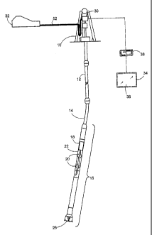
Referring to Fig. 1 a drilling rig 10 controls a drilling operation using a
drillstring 12 that comprises lengths of drill pipe 14 screwed together end to
end. The
drilling rig 10 may be any sort of oilfield, utility, mining or geothermal
drilling rig,
including: floating and land rigs, mobile and slant rigs, submersible, semi-
submersible, platform, jack-up and drill ship. A typical drillstring is
between 0 and
5km or more in length and has at its lowest part a number of drill collars or
heavy
weight drill pipe (HWDP). Drill collars are thicker-walled than drill pipe in
order to
resist buckling under the compression forces: drill pipe may have an outer
diameter
of 127mm and a wall thickness of 9mm, whereas drill collar may have an outer
diameter of up to 250mm and a wall thickness of 85mm for example.
A bottom hole assembly (BHA) 16 is positioned at the lower end of the
drillstring 12. A typical BHA 16 comprises a MWD transmitter 18 (which may be
for
example a wireline telemetry system, a mud pulse telemetry system, an
electromagnetic telemetry system, an acoustic telemetry system, or a wired
pipe
telemetry system), centralisers 20, a directional tool 22 (which can be sonde
or collar
CA 02745062 2013-12-11
- 21 -
mounted), stabilisers (fixed or variable) and a drill bit 28, which in use is
rotated by a
drilling mechanism 30 (such as a top drive) via the drillstring 12.
The drilling rig 10 comprises a drilling mechanism 30. The function of the
drilling mechanism 30 is to rotate the drill string 12 and thereby the drill
28 at the
lower end. Presently most drilling rigs use top drives to rotate the
drillstring 12 and
bit 28 to effect drilling. However, some drilling rigs use a rotary table and
the
invention is equally applicable to such rigs. The invention is also equally
useful in
drilling any kind of borehole e.g. straight, deviated, horizontal or vertical.
A pump 32 is located at the surface and, in use, pumps drilling fluid through
the drillstring 12 through the drill bit 28 and serves to cool and lubricate
the bit
during drilling, and to return cuttings to the surface in the annulus formed
between
the drillstring and the wellbore (not shown).
Drilling data and information is displayed on a driller's console 34 that
comprises a touch screen 36 and user control apparatus e.g. keyboard (not
shown) for
controlling at least some of the drilling process. A digital PLC 38 sends and
receives
data to and from the console 34 and the drilling mechanism 30. In particular,
a driller
is able to set a speed command and a torque limit for the top drive to control
the
speed at which the drill bit 28 rotates.
Referring to Fig. 2 the PLC 38 comprises a non-volatile flash memory 40 (or
other memory, such as a battery backed-up RAM). The memory stores computer
executable instructions that, when executed, perform the function of a speed
controller 42 for the drilling mechanism 30. The speed controller 42 comprises
a PI
controller with anti-windup that functions as described in greater detail
below. In this
CA 02745062 2013-12-11
- 22 -
embodiment the speed controller 42 is separate and distinct from the drilling
mechanism 30. However, it is possible for the functionality of the speed
controller as
described herein to be provided as part of the in-built dedicated speed
controller of a
top drive. Such in-built functionality may either be provided at point of
manufacture
or may be part of a software upgrade performed on a top drive, either on or
offsite.
In other embodiments the PLC may be an analogue PLC.
PI Controller Tuning
The drill string 12 can be regarded as a transmission line for torsional
waves. A
variation of the friction torque at the drill bit 28 or elsewhere along the
string
generates a torsional wave that is propagates upwards and is partially
reflected at
geometric discontinuities. When the transmitted wave reaches the drilling
mechanism
30, it is partially reflected back into the drill string 12. For a top drive
with a high
inertia and/or a stiff speed controller the reflection is nearly total so that
that very
little energy is absorbed by the top drive.
To quantify the top drive induced damping a complex reflection coefficient r
for torsional waves at the drill string/top drive interface may be defined as
follows:
4"¨Z
r = ____________________________
(1)
4-+Z
where 4. is the characteristic impedance for torsional waves and Z is the
impedance
of the top drive. The characteristic impedance is proportional to the cross
sectional
polar moment of inertia for the pipe, and varies roughly as the 4th power of
the pipe
diameter. Note that the reflection coefficient is a complex function where, in
general,
both the magnitude and phase vary with frequency. If the speed control is
stiff (i.e. IZI
CA 02745062 2013-12-11
- 23 -
>> ) then the reflection coefficient approaches -1 and nearly 100% of
the torsional
wave energy is reflected back down the drill string 12 by the drilling
mechanism 30.
A complex representation of the top drive impedance may be derived as
follows. If the anti wind-up of the speed controller is neglected (which is a
non-linear
function that limits torque) the drive torque of the drilling mechanism 30 can
be
written as:
7:1 = Ppõ, + iJ(S2se, S1)dt
(2)
where P and / are respective the proportional and integration factors of the
speed
controller, and 0 is the actual output drive speed (in rad/s) and nse, is the
set point
of the drive speed (in rad/s). The drive torque is actually the sum of motor
torques
times the gear ratio ng (motor speed/output speed, >1). Notice that speed
control here
refers to the output axis of the top drive. It is more common for the speed
control to
refer to the motor axis; in that case the corresponding P and I values for the
motor
speed control would then be a factor I In: lower than above.
Neglecting transmission losses, the equation of motion of the top drive output
shaft is:
c112
-
dt (3)
where J is the effective inertia of the drilling mechanism (including gear and
drive
motors) and T is the external torque from the string. In this embodiment the
effective inertia is equal to the total mechanical inertia of the drilling
mechanism 30.
Combining equations (2) and (3) and applying the Fourier transform gives the
following equation of motion:
CA 02745062 2013-12-11
- 24 -
(ioil + P +¨I = (P + ¨I)Ice, -T
ico ico (4)
For simplicity, the same variable names have been used as in the time based
equations, although û, Q., and T now represent complex amplitudes. The implied
time factor is exP(i"), where i = Ar-11 is the imaginary unit and C17 271f is
the
angular frequency of the drilling mechanism 30. If we assume there is no
cascade
feedback through the set speed (as found in torque feed-back systems), the set
speed
amplitude vanishes and the equation above simplifies to:
T = -(icoJ + P + ¨I)E2
io) (5)
The negative ratio - TM is called the top end impedance Z of the string:
Z = ica + P + ¨I
iC0 (6)
This impedance can easily be generalized to an ideal PID controller, by
adding a new term ÝWD t it, where D is the derivative term of the controller.
A
(normal) positive D-term will increase the effective inertia of the top drive
(as seen
by torsional waves travelling up the drill string), while a negative factor
will reduce
it. In practice, because time differentiation of the measured speed is a noise
driving
process that enhances the high frequency noise, the D-term in a PID controller
is
normally combined with a low pass filter. This filter introduces a phase shift
that
makes the effective impedance more complicated and it therefore increases the
risk of
making instabilities at some frequencies, as explained below. Therefore,
although a
PID controller with a D-term could be used to perform the tuning aspect of the
invention, it is not recommended. However, in another aspect of the invention
described below, we have found a way to adjust the effective inertia of the
drilling
mechanism without this disadvantage.
CA 02745062 2013-12-11
- 25 -
Combining equations (1) and (6) gives the following expression for the
reflection
coefficient, valid for PI type speed controlled top drives:
P - + i = (coJ - ¨I)
Ü)
r=-)
P++i= (cal - ¨I)
co (7)
Its magnitude has a minimum equal to:
=
1P-4
min p
(8)
when the imaginary terms vanish, that is, when the angular frequency of the
drilling
mechanism 30 equals a' = . For standard
stiff speed controllers this frequency
is normally higher than the stick-slip frequency (see Fig. 3 and associated
description). However, we have discovered that adjustment of the 1-term of the
PI
controller also adjusts the peak absorption frequency of torsional waves by
the
drilling mechanism 30. In particular, the I-term can be adjusted so that the
maximum
energy absorption of torsional waves occurs at or near the stick-slip
frequency cos (i.e.
when the magnitude of the reflection coefficient is minimum) as follows:
(0,2 j
(9)
This realization is significant since, as a first step to achieving good
damping,
the I-term of the PI controller is only dependent on the stick-slip frequency
and the
effective inertia of the drilling mechanism 30. Since the effective inertia is
readily
determined either in advance of operation or from figures quoted by the
manufacturer, and since the stick-slip frequency can be readily determined
during
drilling, this makes tuning of the PI controller straightforward whilst
achieving good
energy absorption by the drilling mechanism 30 of the stick-slip oscillations.
CA 02745062 2013-12-11
- 26 -
This first step in tuning the speed controller is a good first step towards
effective dampening of stick-slip oscillations. However, the damping can be
further
improved. In particular the untuned P-term of the speed controller is still
too high,
that is P >> 4- keeping the reflection coefficient close to -I. We have
discovered that
to obtain sufficient damping of the stick-slip oscillations the P-term of the
speed
controller must be lowered so that it is of the same order of magnitude as the
characteristic impedance 4- . However, we have also discovered that it is not
desirable that the reflection coefficient vanishes completely, because that
would
radically change the dynamics of the drill string 12 and the pendulum mode
would
split into two new modes, each with a different frequency. Furthermore an
extremely
soft speed controller that absorbs nearly all of the incident wave energy will
cause
very high speed fluctuations of the drilling mechanism 30, in response to
variations
of the downhole torque. This can reduce drilling efficiency.
We have discovered that the P-term can be selected as a non-integer multiple
of the characteristic impedance 4- of the drill string, which may be expressed
as
P Cla where a is a normalised mobility factor (dimensionless) less than
unity,
which is operator or computer adjustable within certain limits as described
below.
Having set the 1-term to cause the imaginary part of equation (7) to vanish,
setting the
P-term as described causes the minimum of the reflection coefficient (i.e. the
peak
absorption of energy by the top drive) at the stick-slip frequency cos to
become:
l -a
rj
nnn -17¨+a (10)
By permitting adjustment of the mobility factor a, the amount of energy
reflected back down the drill string 12 can be controlled, within limits.
These limits
can be set by permitting only a certain range of values for a, such as 0.05 to
0.33.
This corresponds to a range for the magnitude of rõõõ from about 0.9 to 0.5.
It is
believed that this range enables the damping to be controlled so that stick-
slip
CA 02745062 2013-12-11
- 27 -
oscillations can be inhibited. If the speed controller 42 is much stiffer than
this (i.e. a
reflection coefficient greater than about 0.9) we have found that too much of
the
torsional energy of the stick-slip oscillations is reflected back down the
drill-string
12. Furthermore, if the speed controller 42 is too soft (i.e. a reflection
coefficient less
than about 0.5) we have found that drilling performance (e.g. in terms of ROP)
can be
affected.
A standard speed controller is designed to keep the motor speed constant and
the true P and I constants refer to the motor axis. A typical drive motor with
a
J
nominal power of 900 kW and a rotor inertia of =25kgm2 is typically controlled
by a motor speed controller of Pin = 500Nms . The speed controller 1-factor is
most
often given indirectly as the P-factor divided by a time integration constant
of
typically r, = 0.3s . As an example, assume a drive with one motor connected
to the
output shaft with a gear having an inertia Jg 250kgm2 and a gear ratio of n g
=5.32
The effective drive inertia (i.e. total mechanical inertia) is then
J g = 960kgm2
The effective speed controller factors referred to the
P ¨ ¨ n 2P ¨ 14000Nms / = PI z 47000Nm . In
output shaft is similarly g nt and
comparison, the characteristic impedance for a typical 5 inch pipe with
c340Nms
which is only 2.4% of the real part of the drive impedance.
Fig. 3 is a graph 48 of the magnitude of the reflection coefficient Ill versus
frequency and shows the difference between a standard stiff speed controller
(curve
50) and a speed controller tuned according to the invention (curve 52). The
latter is
calculated with a mobility factor of a = 025 and an I-term providing maximum
damping at 0.2Hz (5s stick-slip period). At this frequency the reflection is
reduced
from about 0.993 (standard P1 controller) to 0.6 (PI controller tuned as
above), which
CA 02745062 2013-12-11
- 28 -
represents a dramatic improvement in the damping by the top drive at the stick-
slip
frequency.
It is worth emphasizing the fact that in both cases the reflection coefficient
stays below 1 but approaches this limit as the frequency approaches either
zero or
infinity. Therefore, the standard PI-controller never provides a negative
damping that
would otherwise amplify torsional vibration components. However, the damping
is
poor far away from the relatively narrow the absorption band at 1-2Hz. In
contrast,
the tuned PI controller provides a comparatively wide absorption band with
less than
3.0 80% reflection between about 0.1Hz and 0.4Hz. There is even a
substantial damping
effect remaining (11.1=0.965) at 0.6 Hz, which is three times the stick-slip
frequency
and close to the second resonance frequency of the drill string.
The effective inertia J of the drilling mechanism, the characteristic
impedance
C and the stick-slip frequency cos change the absorption bandwidth of the
frequency-
reflection curve in Fig. 3. In particular, the absorption bandwidth is
inversely
proportional to the ratio a), J/c For a drilling mechanism with a large
effective inertia
and/or a slender drill pipe making this ratio larger (e.g. greater than 5),
the absorption
bandwidth narrows. In that case, it becomes more important to ensure that the
estimated stick-slip period is determined more accurately (if possible) so
that the
frequency of maximum damping is as close as possible to the actual stick-slip
frequency.
The reduction in reflection coefficient magnitude and corresponding positive
damping over the entire frequency band is very important and is achieved with
only a
single P1 controller. This is in contrast to other active methods that use
cascade feed-
back loops in series with a standard speed controller, or that rely on some
measured
parameter such as drive or string torque to provide a feedback signal to the
PLC. The
CA 02745062 2013-12-11
¨ 29 ¨
filters used in the cascade feed-back functions can be suitable for damping
the
fundamental stick-slip oscillations but they can cause negative damping and
instabilities at higher frequencies.
In practice, the P-term for the tuned speed controller may be determined as
follows:
4- GI
P
a ca
where G is the shear modulus of the drill string (typical value is 80x109Nm-
2), /p is
the cross-sectional polar moment of inertia of the drill string (typical value
is
3.0 12.2x10⁻⁶ M4) and c is the speed of torsional waves in the drill string
(typical value is
3192ms-1).
To determine the I-term in practice, there are two variables to be estimated:
(a) the angular frequency cos of stick-slip oscillations, and (b) the
effective inertia Jof
the top drive. The latter is relatively straightforward to determine and can
either be
calculated from theoretical values of the gear inertia, the gear ratio and the
motor
rotor inertia, or it can be found experimentally by running an acceleration
test when
the drilling mechanism 30 is disconnected from the string. A typical formula
for
calculating top drive inertia Jd is:
Jd= Jg + n in n g 2J in
where Jg is top drive inertia with the motor de-coupled (typical value 100
kgm2), ng is
the gear ratio (>1), nn, of active motors (default value is 1), and J,õ is the
rotor inertia
of the motor (typical value is 25 kgm2).
CA 02745062 2013-12-11
- 30 -
There are several ways that the angular frequency cos may be estimated,
including: (i) calculations from string geometry, (ii) by manual measurement
(e.g.
using a stop watch) and (iii) by automatic determination in the PLC software.
An
important advantage of the PI tuning aspect of the invention is that the
damping
effect of stick-slip oscillations is still obtained even if the estimate of
the stick-slip
period used to tune the PI controller is not very accurate. For example, Fig.
3 shows
maximum damping occurring at a frequency of 0.2Hz. Even if the real stick-slip
frequency is lower or higher than this, there is still a good damping effect
(r - 0.8)
obtained between about 0.09Hz and 0.4Hz. Accordingly, the methods used to
estimate stick-slip period do not have to be particularly accurate.
(i) String Geometry
It is possible to take a theoretical approach to determine the stick-slip
period
using parameters of the drill-string available on-site in the tally book. A
tally book is
compiled on site for each drill string and comprises a detailed record of the
properties
of each section of drill string (e.g. OD, ID, type of pipe), a section being
defined as a
length (e.g. 300m) of the same type of drill pipe.
In the following it is assumed that the drillstring 12 consists of one drill
pipe
section of length / with a (unwed bit impedance at the lower end, represented
by b .
J =
This impedance can be a pure reactive inertia impedance (iailb ,where b is the
inertia of the bottom hole assembly) or it can be a real constant representing
the
lumped damping (positive or negative) at the drill bit 28. The torque
equations at the
top and at the bit represent the two boundary conditions. It can be shown that
these
two boundary conditions can be written as the following matrix equation.
CA 02745062 2013-12-11
- 31 -
-
+ Zd Zõ ['1_o1
- Zb)e-/kI (C+ Zb)e' _ o]
(11)
where k is the wavenumber and Zd is the impedance of the drilling mechanism.
No-trivial solutions to this system of equations exist if the determinant of
the
system matrix vanishes, that is, when
ern, ¨ (4- ¨Zd)(4- Zb)
r r
(4- + Zd)(4- Zb) d (12)
Here reflection coefficients at the drive rd and at the bottom of the drill
string
rb have been introduced as follows:
Zd
Ǩ Z,,
d
Zõ Zb
Notice that the top drive reflection coefficient rd for a stiff speed
controller (11
) and the bit reflection coefficient rb equals unity for a free lower
end (Zb =0).
The roots of equation (12) can be written as:
i2k1 = In(r, ) = In1rd rb1+ i(m27r + ad + ab)
(13)
where ni is a non-negative integer and ad and Ceb are the arguments (phase
angles) of
the complex reflection coefficients rd and /1 , respectively. The
corresponding angular
resonance frequencies are
c
con = (ad + a, + m27r - i In1rd rb1)-
21 (14)
CA 02745062 2013-12-11
¨ 32 ¨
Since, in general, the magnitudes and phases of the reflection coefficient are
frequency dependent, the above equation is transcendent, without explicit
analytic
solutions. However, it can be solved numerically by a PC or other computer.
The imaginary term of the above equation represents the damping of the
Irri<1
eigenmodes. If t" the imaginary part of the root is positive, thus
representing a
normal, positive damping causing the time factor exP(i6),,t) to decay with
time. In
contrast,rl>1
if r
ldb the damping becomes negative, causing a small amplitude to
grow exponentially with time.
As an example, consider a case with a completely stiff speed controller (
and ad = ) rotating a drill string having a finite bottom hole inertia (
= /cab Ird = 1 a = -2 tan -1 (0 b
11 / 4")
and b ). Then the
lowest (theoretical stick-
slip) frequency co, becomes:
( c-,,,
.
(Os = - 2 tan sb
\. 4- 21 (15)
With no extra bottom hole assembly inertia this expression reduces to cp' =
1(21)
Notice that the resonance frequency decreases as the inertia' jb increases. In
the
V./bC
extreme case when wsib C the above formula can be rewritten as 1/
where C = l/(GI
) is the static compliance of the string. This is the well-known
formula for the natural frequency of a lumped inertia and spring system.
CA 02745062 2013-12-11
- 33 -
We have found that it is useful to study the relation between lower end speed
amplitude I/ Cl(x = 1) T T (x = 0) . It can be
and the corresponding top torque s
shown from the equations above that this ratio is
rd exp(-ikl) + exp(ikl) . sin(k/) (1+ 10 cos(k1)
(rd -1) (1 - ri)C (16)
Using the fact that characteristic impedance can be written as 4- r"-kl -
/(cpC) the down
hole speed amplitude can be expressed by
= sin(k/) C = icoT (1+ rd)cos(ki) CcoT
C2
kl
(1 - rd)kl
(17)
Notice the that the second term vanishes if the speed controller is very
stiff(
r '="- -1) or when kl it I 2. However if a soft speed controller is used and
there is a
high inertia near the bit so that kl for the stick-slip frequency is
significantly less than
it/2, then the second term may be significant and should not be omitted.
The theory above can be generalized to strings with many sections and also to
cases with distributed damping. If a linear damping term is included, the
generalization causes the wave number and characteristic impedances to be
complex
and not purely real. If the string consists of n uniform sections the general
wave
solution consists of 2n complex speed amplitudes, representing pairs of up and
down
propagating waves. Continuity of angular speed and torsion across the section
boundaries can be expressed by 2(n - 1) internal boundary conditions, which
add to
the two end conditions in equation (11). These can be set up as a homogeneous
2n x 2n matrix equation. The roots of this system of equations are those
frequencies
making the system matrix singular. Although it is possible to find an analytic
expression for the system determinant, the solutions are found numerically by
a PC or
CA 02745062 2013-12-11
- 34 -
other computer on site. IADC/SPE 15564 by Halsey, et al., entitled
"Drillstring
Torsional Vibrations: Comparison Between Theory and Experiment on a Full-Scale
Research Drilling Rig", SPE Annual Technical Conference and Exhibition, 5-8
October 1986, New Orleans, Louisiana, provides an example of one way to do
this.
Figs. 4A' and 4A" shows a typical window 54 available on the driller's
console that enables the driller to trigger a PC to estimate a new stick-slip
period
based on string geometry. In particular a table 51 represents the sections of
the
drillstring including BHA, heavy-weight drill pipe (HWDP), and drill pipe
sections 1
to 6. Available fields for each section are: length, outer diameter and inner
diameter.
The driller firstly determines from the on-site tally book how many sections
the drill
string is divided into. In this example the drill string has eight sections.
For each
section the driller enters figures into the three fields. A button 55 enables
the driller to
trigger a new stick-slip period to be estimated based on the string geometry
entered in
the table 51. In particular, the table establishes the 2n x 2n matrix equation
mentioned above and the PL (not shown) uses a numeric method to find the roots
of
the matrix that make the matrix singular. The smallest root is the stick-slip
period
output 56 in the window 50.
(ii) Manual Estimation
To determine the stick-slip period manually, the driller may observe the drive
torque as displayed on the driller's console 34 and determine the period by
measuring
the period of the variation of the drive torque with a stopwatch. This is
readily done
since each period is typically 2s to 10s. An alternative method is for the
driller to
listen to the change in pitch of the top drive motor and to time the period
that way. As
mentioned above, such methods should be sufficient as the estimated sick-slip
CA 02745062 2013-12-11
- 35 -
frequency does not have to be particularly close to the real stick-slip
frequency in
order that the stick-slip oscillations are damped.
(iii) Automatic Estimation
Automatic estimation means that the PLC software estimates the stick-slip
period or frequency from measurements made during drilling. In particular, the
top
drive torque signal is filtered by a band-pass filter that passes frequencies
in the range
0.1Hz to 0.5Hz (i.e. a period of between 2s and 10s), that is the filter
favours the
stick-slip component and suppresses all other frequency components. The PLC
then
detects the period between every new zero up-crossing of the filtered torque
signal
and uses these values in a recursive smoothing filter to obtain a stable and
accurate
period estimate. The final smoothing filter is frozen when either the stick-
slip
severity (see below) falls below a low critical value, or the tuning method is
activated.
To help the period estimator to quickly find the accurate period, the operator
can either put in a realistic starting value or pick a theoretical value
calculated for the
actual string (determined as per String Geometry section above).
In use, the tuned PI controller is activated when there is a significant stick-
slip
motion (as determined by the driller or by software). However, the stick-slip
frequency estimation (period measurement) takes place before the tuned PI
controller
is actually used to control the drilling mechanism. Once complete the period
estimator is turned off when PI controller is on, because the natural period
of the
stick-slip oscillations can change slightly when soft speed control is used.
CA 02745062 2013-12-11
- 36 -
There does not appear to be a need for very frequent retuning of the estimated
frequency because the natural stick-slip frequency varies slowly with drill
string
length. It is a good idea, however, to automatically update the period at
every
connection i.e. when another 30 m of drill pipes are added to the drill
string. To do
that it is possible to use theoretical sensitivity analysis to predict how the
stick-slip
period increases with drill string length. One way to do this (but not the
only way) is
to find the theoretical periods for two string lengths (L and L+200 m, say)
and then
use interpolation for the increase caused by the addition of a 30m section in
order to
update the estimated period.
Estimation of Stick-Slip Severity and Instantaneous Bit Speed
An additional aspect of the invention is provided as a set of computer
executable instructions in the PLC software that enables quantification of bit
speed
variations and an estimate of the instantaneous bit rotation speed. 'Bit
speed' means
the BHA rotation speed excluding the contribution from an optional mud motor.
This
aspect of the invention may be provided separately from or in combination with
the
PI controller tuning aspect of the invention.
This estimation is achieved by combining the known torsional compliance C
of the drill string and the variations of the drive torque. In general, since
the torque is
not a strictly periodic signal but often possess a wide range frequencies, an
accurate
calculation is extremely complicated and is therefore not suitable for
implementation
in a PLC. However, we have realised that since the stick-slip motion is
dominated by
the fundamental stick-slip frequency, it is possible to achieve fairly good
estimates
based on this frequency only.
CA 02745062 2013-12-11
- 37 -
The key equation is (17) above, which describes a good approximation for the
complex speed amplitude as a function of the top string torque. The two terms
in this
expression must be treated differently because they represent harmonic
components
having a 90 degrees phase difference. While the imaginary factor lairs should
be
treated as the time derivative of the band pass filtered torque, the real term
factor airs
can be approximated as the product of the band pass filtered torque and the
stick-slip
frequency. Since the band pass filter suppresses all frequencies except the
stick slip-
frequency, it is possible to substitute direct time integration by an
integration based
-co,'
approximation. This approximation is based on the fact that ico /(ico),
where
1/(ico) represents time integration. This approximation favours the stick-slip
frequency and suppresses higher harmonics. The time domain version of (17)
suitable
for implementation in the PLC 38 is:
sin(kl) = dTbP (1+ rd )cos(Id) Cco T sin(k/) C = co 2 T dt
kl dt (1- rd)kl s bp
kl bp
(18)
Here the phase parameter kl =1 I c . In the last approximation the integral
approximation for time derivation is used and the second term is omitted.
Even though the formula above is based on a single section string, simulations
have shown that it also provides good estimates for multi-section strings if
the total
string compliance C is used:
m 1 /
C=EI G
J =I pj (19)
A version of the algorithm implemented in the PLC 38 to estimate both
instantaneous BHA speed and a stick-slip severity, comprises the following
steps.
CA 02745062 2013-12-11
- 38 -
1. Estimate the string torque by correcting for inertia effects (subtract
the
effective motor inertia times the angular acceleration) and by using the gear
ratio to
scale it properly;
2. Band pass filter the estimated torque with a band pass filter centred at
the observed/estimated stick-slip frequency. The filter should be of 2nd order
or
higher, but can preferably be implemented in the PLC as a series of 1st order
recursive IIR filters;
3. Calculate the total static drill string compliance using equation (19)
above;
4. Calculate the phase parameter kl = co1 I c where ws is the determined
angular stick-slip frequency;
5. Calculate the dynamic downhole speed by using either the accurate or
the approximate version of equation (18) above;
6. Calculate the "stick-slip severity" o, which is the normalized stick-
slip
amplitude, determined as the ratio of dynamic downhole speed amplitude over
the
mean top drive rotational speed;
7. Find the instant speed as the sum of the low pass filtered top drive
speed and the estimated dynamic downhole speed. Clip to zero if the estimated
speed
goes negative;
8. Output data to be plotted on a graph (e.g. RPM versus time) shown on
a display on a driller's console for example;
9. Repeat steps 1 to 8 to provide substantially real-time estimate
of bit
speed.
It is envisaged that this method could be performed where only the BHA
speed estimate is output or only the stick-slip severity is output.
CA 02745062 2013-12-11
- 39 -
Regarding step 6, a possible way of estimating the stick-slip severity is to
use
the following formula where LP() denotes low pass filtering:
o-
V2- LP(0h2)
ser (20)
Because the above method takes the reflection coefficient into account, it
applies both for a standard and tuned speed control. During acceleration
transients
when the top drive speed is changed significantly the estimator is not
reliable but can
give large errors. Nonetheless we believe this is a useful tool for assessing
downhole
conditions, either automatically in software or by display for analysis by a
driller.
The ratio of dynamic speed amplitude to the average top drive speed is a
direct and quantitative measurement of the stick-slip motion, more suitable
than
either the dynamic torque or the relative torque amplitude. Even though the
estimated
bit speed is not highly accurate, it provides a valuable input to the driller
monitoring
of it in a trend plot will give the operator more explicit information on what
is
happening at the bit.
User interface
A user interface is provided for the driller's console 34 that comprises a
graphical interface (see Figs. 4A' and 4A", and 4B' and 4B") which provides
the
operator with direct information on the stick-slip status. Stick-slip is
indicated by
three different indicators:
CA 02745062 2013-12-11
- 40 -
= A "traffic light" indicator 58 in Fig. 4A' with 3 levels of stick-slip: a
green
light for small amplitudes (0-30%), a yellow warning light if the speed
oscillations
are significant (30-70%) and finally a red light if even higher amplitudes are
estimated. This percentage value is based on the stick-slip severity as
determined
above.
= The stick-slip severity is plotted in a plot 62 of torque versus time in
Figs. 4B'
and 4B" to see how the stick-slip has developed over a specified period of
time.
= The instant bit speed estimate in a plot 64 of instantaneous bit speed
versus
time in Fig. 4B giving a visual and direct impression of the down hole stick-
slip
status.
As mentioned above, the window 50 requires the operator to input a rough
description of the string, in terms of a simplified tally. This tally accepts
up to 8
different sections where the length, outer diameter and mass per unit length
are
specified. This information is used for calculating both the theoretical
estimated
frequency for the lowest mode and the static drill string compliance at this
frequency.
The operator can switch the tuned PI controller on or off. In the off state,
the
standard drive speed controller is used. When the tuning is turned on, this
speed
controller is bypassed by the tuned PI controller 42 which is implemented in
the PLC
38. If the drive controller in the drilling mechanism 30 is a modern digital
one, it is
also possible to change drive speed controller itself, instead of bypassing
it. However,
if the bypass method is chosen, this is achieved by sending a high speed
command
from the PLC 38 to the speed controller in the drilling mechanism 30 and by
controlling the output torque limit dynamically. In normal drilling this
torque limit is
used as a safety limit preventing damage to the string if the string suddenly
sticks. In
the tuned control mode, when the PLC 38 controls the torque limit dynamically,
this
limit is substituted by a corresponding software limit in the PLC 38.
CA 02745062 2013-12-11
- 41 -
The operator can also change the prevention or mobility factor a within preset
limits via buttons 60, typically between 0.05 and 033. A high factor implies a
softer
speed control and less probability for the stick-slip motion to start or
persist. The
disadvantage of a high factor is larger fluctuations of the top drive speed in
response
to harmless changes in the string torque level. It may be necessary to choose
a high
factor to cure severe stick-slip oscillations but the operator should reduce
the factor
when smooth drilling is restored.
It is envisaged that the decision to activate and de-activate the tuned speed
control may be taken by the PLC 38 or other electronic controller. Such a
controller
may monitor the instantaneous estimate of bit speed as set out above. When a
period
pattern of stick-slip is observed, the controller may activate the tuning.
Furthermore
the controller may gradually increase the mobility or prevention factor to
increase the
softness of the drilling mechanism 30 if the stick-slip oscillations do not
reduce in
magnitude over a predetermined period e.g. 2 minutes. Once the stick-slip
oscillations have reduced or substantially disappeared the controlled may
gradually
reduce the mobility factor (e.g. down to a = 0.1) to improve drilling
efficiency.
HIL Testing
The PI tuning method has recently been extensively tested in so-called
Hardware In the Loop (HIL) simulations. In these tests the PLC programs are
run on
a physical PLC interfacing to a real-time simulation model of the drive and
the drill
string.
CA 02745062 2013-12-11
- 42 -
The simulation model being used for the HIL testing of tuning method has the
following features:
1. The drive is modelled as a standard PI speed controller with torque
and power limitations and anti-windup. The torque or current controller is
perfect in
the sense that the actual torque is assumed to match the set torque with no
delay.
2. The model can handle a plurality of drive motors connected to the
output shaft by a gear.
3. The drill string is modelled as a series of lumped inertia and spring
elements derived from any tally book. The grid length used in most examples
below
is approximately 28m, which is the typical length of a triple stand. Hence the
3200m
long string used below consists of 114 elements.
4. The static friction torque is calculated for every element, based on the
theoretical contact force being a function of weight and inclination,
curvature and
tension. The effect of WOB and bit torque is also included.
5. The dynamic, speed dependent friction torque is modelled as a sum of
three terms. The first term is a soft-sign variant of the Column friction, the
second
represents and extra static start friction and the third is a linear damping
term,
independent of the contact force. To simulate instability with growing
oscillation
amplitude from smooth drilling, this damping coefficient must be negative.
The model was first developed as a Simulink model under the Matlab
environment. It is later implemented with the Simulation Module toolbox under
the
National Instrument LabView environment and run on a powerful PC platform.
Although this PC is not using a real time (RT) operative system, its high
power
makes the model RT for all practical purposes.
CA 02745062 2013-12-11
- 43 -
The LabView simulation program is linked to the PLC a so-called SimbaPro
PCI profibus DP (Distributed Peripherals) card, which can simulate all DP
nodes
connected to the PLC. The update time is set to 10ms (100Hz), which is within
the
PLC cycle time (typically 20ms).
Results from the H1L testing are shown in Fig. 5. The string used is a 3200m
in length similar to the string used in the field test (see below). The
theoretical period
for the lowest mode is 5.2s. Fig. 5 shows a graph 70 of the torque and speed
for the
drillstring (trace 72) and for the top drive (trace 74) during a 150s period
including a
5s interval where the top drive speed is accelerated from zero to 100 rpm. The
tuned
speed control is turned on 30s after start of rotation. Steady stick-slip
oscillations are
established soon after the start up. The stick-slip period stabilizes around
5.3s. This is
slightly longer than the theoretical pendulum period, but the extended period
is
consistent with the fact that the sticking interval is substantial. Note that
the top drive
speed is nearly constant during this part of the speed control.
When the tuned speed control is turned on, the top drive speed (trace 78)
temporarily shows a pronounced dynamic variation 79 in response to the large
torque
variations. But after a few periods the stick-slip motion fades away and the
top drive
speed, as well as the bit speed, become smooth. When tuned speed control is
turned
off again, the down-hole speed (trace 76) amplitude starts to grow over the
period 77,
until full stick-slip motion is developed. This instability is a consequence
of the
negative damping included in the string torque model.
Fig. 6 shows results 80 from the same simulations, but now with focus on the
PLC estimated stick-slip severity (trace 87) and instantaneous bit speed
(trace 84) -
note that the lower graph is a continuation of the upper graph and shows the
difference between simulated speed (trace 84) and estimated speed (trace 86).
The bit
CA 02745062 2013-12-11
- 44 -
speed estimate is fairly good during steady conditions but has significant
error during
start-up. Despite this, the estimated bit speed is able to provide the driller
with a
useful picture down hole speed variations. The effectiveness of the tuned
speed
controller is clearly illustrated by the trace 87 of stick-slip severity: when
tuned speed
control is in use, the stick-slip severity falls almost to zero. Once tuned
control is
switched off, the stick-slip severity increases once again.
Field Test
The tuning has been tested in the field, while drilling a long deviated well.
The string was approximately 3200 m long with a 5.5 inch drill pipe.
Unfortunately,
the test ended after a relative short period of severe stick-slip conditions,
when the
PDC bit drilled into a softer formation. The new formation made the bit less
aggressive with less negative damping, thus removing the main source of the
stick-
slip oscillations.
Fig. 7 shows an example where stick-slip motion is developed while rotating
with the standard stiff speed controller. Two graphs 90 are shown: one of
drive
torque versus time, and the other of bit speed versus time. A few comments on
these
graphs are given below:
= The data was recorded from the PLC at a sampling rate of approximately 9
Hz.
= The "TD corrected" torque (trace 92) is the estimated string torque and
equal
to the measured drive torque corrected for inertia effects.
= The TD corrected torque as well as the bit speed are estimated by post
processing the recorded data using the methods described above.
CA 02745062 2013-12-11
- 45 -
= The standard top drive speed controller is very stiff, because variations
of the
measured speed (trace 94) can barely be seen after turning off the tuned speed
control
and the top drive rpm is virtually constant. The corresponding small
accelerations are
the reason why the measured drive torque almost matches the inertia corrected
string
-- torque during this period.
= The high frequency torque oscillations (at 1.1 Hz) seen during first part
of the
trace 96 when tuning is on probably come from a higher mode resonance in the
drill
string. These vibrations seem to be independent of the type of speed
controller used,
but they vanish when stick-slip is developed.
= The prevention factor (line 98) is the operator set mobility factor a
mentioned above.
= The observed stick-slip period is approximately 5.2s, which is in good
agreement with the theoretical period for this particular string.
Another example of successful curing of stick-slip motion is shown in Fig. 8.
In this figure a similar graph 100 to graph 90 is shown:
= The "TD set" speed (trace 102) is the speed command sent to the drive.
When
the tuning is turned on, this level is raised so the bypassed drive speed
controller
always tries to increase the torque beyond the dynatnic limit of the new speed
-- controller. In this case the speed increase is a slightly too small,
causing the dynamic
speed to be clipped by the drive speed controller. This clipping will reduce
the
damping effect under the tuned PI controller.
= When tuning is turned on, the mobility factor (line 104) is approximately
15%. This is a little too low, because stick-slip oscillations are not cured
before the
-- operator increases this factor at 106.
CA 02745062 2013-12-11
- 46 -
= After the stick-slip motion has faded at about 4310s, the 1.1Hz
oscillations
reappear with an amplitude similar to what was observed before. But now the
vibrations are seen also in the measured speed.
= Additional data, not included here, show that the 1.1Hz oscillation
amplitudes
decrease but do no vanish completely when the mobility factor is further
increased. It
means that even though the top drive impedance is inertia dominated at this
frequency the soft PI controller also has some dampening effect on higher mode
oscillations as well.
Higher Stick-Slip Modes
The stick-slip damping method described above works very well in a wide
range of cases. However, extensive Hardware-In-the-Loop (HIL) simulation
testing
has revealed a further problem when the string is extremely long (typically
5000m or
more) and the measured i.e. fundamental stick-slip period exceeds about 5-8s
i.e. a
frequency to, of about 0.2 - 0.13Hz. The method is still able to damp the
fundamental
mode stick-slip oscillations, but as soon as these oscillations are dampened,
the
second natural mode tends to become unstable and grow until full stick-slip is
developed at that second mode. This second mode has a natural frequency which
is
approximately three times higher than the fundamental stick-slip frequency
cos. The
higher order stick-slip oscillations are seen as short period (less than about
1/3 of the
fundamental stick-slip period) and large amplitude (greater than about 2kNm)
cyclic
variations of the drive torque. We have also found via simulations that,
during second
mode stick-slip oscillations, the bit rotation speed varies between zero and
peak
speeds exceeding twice the mean speed.
CA 02745062 2013-12-11
- 47 -
Simulations have shown that the system sold under the trade mark SOFT
TORQUE also suffers from the same problem. Neither system is able to damp at
the same time both the first and second mode stick-slip oscillations.
We have discovered that by reducing the effective inertia of the drilling
mechanism this problem can be addressed. There are several ways that the
effective
inertia can be reduced including making a relatively small change in the tuned
PI
controller described above, and selecting a higher gear in the drilling
mechanism.
Advantages of reducing the effective inertia include: more effective damping
of
higher modes, and increased tolerance in the method to errors in the estimated
stick
slip frequency. There are two ways we have identified to reduce the effective
inertia
of the drilling mechanism: by tuning of the speed controller and by changing
gear (if
possible). Each will be described below.
Speed Controller Tuning to Dampen Higher Modes
For clarity, the first embodiment of the speed controller 42 described above
will be referred to as the 'tuned PI controller' and the second embodiment of
the
speed controller 42 described below will be referred to as the 'inertia
compensated PI
controller'.
Before describing the optional improvement to the method, we first set out a
basic description of the higher modes of torsional string oscillations. As
described
above (see equations (14) and (15)) the natural angular frequency for mode in
of a
lossless string rotated by top drive with zero mobility is given by:
CA 02745062 2013-12-11
- 48 -
coõ, = /2ni -1- ¨2 tan-, r co õ,Jb" 7re
7r 2/
(21)
where
m is a positive integer indicating mode number (m = 1 for the lowest mode);
jb is the inertia of the bottom hole assembly (BHA);
C is the characteristic impedance of the drill pipes;
C is the sonic speed for torsional waves; and
/ is the length of the drill pipe section (excluding the BHA length).
It is convenient to introduce the normalized frequency
2/
com
7tC (22)
and the normalized inertia
7reh = r = I 1)
¨14"
dp (23)
Here we have used the fact that the characteristic impedance can be expressed
as
¨ jdPC 11 , where j dP represents the total inertia of the drill pipes. The
frequency
equation (21) can now be written as:
= 2
777 ¨ 1 ¨ ¨2 tan -I
rnJb
z 2 (24)
CA 02745062 2013-12-11
¨ 49 ¨
For non-zero inertia values this equation is transcendental, which means that
it has no explicit analytical solutions and must be solved numerically, as
described
above. Referring to Fig. 9 a graph 110 shows the three lowest roots (m = 1,
112; m =
2, 114; m = 3, 116) versus the normalized inertia b . Frequency ratio curves
118, 119
show that the ratio is nearly constant and approximately equal to 2m ¨1 for
small
BHA inertia (ib 1). In practice, very long drill strings (> 5 km) used for
extended
horizontal reach, have quite small and light BHAs (without drill collars or
heavy
weight drill pipes) to limit the total friction torque. Therefore, the low
inertia ratios 3
and 5 for the second and third modes respectively are very good approximations
to
reality.
The corresponding mode shapes for the dynamic rotation speed can be found
from the wave numbers km , which can be written as:
(Dm 71.
km = =
c 2/ " (25)
The corresponding eigenfunctions describing how the angular speed
amplitude varies with depth, are
71" Z
= sin(kõ,z) = sin( "1
2/ , (26)
where z is depth referred to the top drive position.
Referring to Fig. 10 a graph 120 shows the mode shapes m 0.25 ;" for the
three lowest modes for the case when Jb = 1 . The Y-axis represents normalized
depth
zn /1. It is apparent that the bit (lower string end where z = -1) is
close to an
anti-node, for all three modes.
CA 02745062 2013-12-11
- 50 -
We have discovered that the speed controller 42 can be improved to counter
stick-slip of the drill bit at both the first and second modes and, to some
extent,
higher modes of stick-slip oscillation. The basis for the improvement is found
in the
equation of angular motion of the drilling mechanism 30. Referring to equation
(3)
above, the equation of motion for the drilling mechanism 30 can be expressed
by:
dfl =Td -T
d dt
where the torque Td of the drilling mechanism is given by:
df2
Td = c P(use, - Q) + - 0)dt
dt (28)
and where
d is the total mechanical drive inertia (including gear and drive motors);
jc is a computer or manually controllable compensation inertia;
P is the speed controller P-factor (referred to output shaft);
is the speed controller 1-factor;
Re/ is the angular set speed; and
Q is the actual top drive speed as measured.
Thus the speed controller uses three terms to control the torque Td applied by
the drilling mechanism 30 to the drill string. The second two terms on the
right-hand
side are familiar from equation (2) above.
CA 02745062 2013-12-11
- 51 -
The first term on the right-hand side of equation (28) is the key component
for
extending the functionality of the tuned PI controller of the first
embodiment. In
contrast to a normal derivative term of a PID controller, which is
proportional to
derivative of the speed error, the new speed controller term is proportional
to the
derivative of the measured speed only. The proportionality factor j, is called
the
compensation inertia because it has dimensions of inertia and it reduces the
effective
inertia of the drilling mechanism 30. This is seen by combining equations (2)
and
(28), and moving this derivative term over to the left hand side:
(Jd - J c)dS) =- + /5 - (2)dt -T
dt (29)
This is the equation of motion for a drilling mechanism 30 with a reduced
inertia using a conventional or tuned PI speed controller. The advantage of
this inertia
reduction is that the absorption bandwidth of the drilling mechanism 30 is
increased,
as explained below. Furthermore, since is software controllable, inertia
compensation can be switched on and off readily in the speed controller and,
when
on, can be adjusted either in real-time if needed. Alternatively, it is
possible to allow
the driller to set j c manually via the driller's console for example.
Following the same methodology as described above in conjunction with
equation (6) above, the effective torsional impedance can be written as the
complex
function:
Zd = ico(J,, - Jc)+ P
iw (30)
CA 02745062 2014-08-20
- 52 -
where i 4:71 is the imaginary unit and 0) is the angular frequency. The
corresponding reflection coefficient rd for the drilling mechanism 30 is
P-c+i-(co(J
d c
rd = ___________________________
P + i = (a)(J
d
(3U
where 4- is the so-called characteristic impedance of the drill pipe and
represents the
ratio of torque and angular speed for a progressive wave propagating along the
drill
string 12. This complex reflection coefficient represents both amplitude and
phase of
the reflected wave when a unit incident torsion wave, which propagates upwards
in
the drill string 12, is reflected at the top. The magnitude of this reflection
coefficient
is strongly related to the torsional oscillations as described above in
conjunction with
the tuning of the speed controller 42 to dampen the fundamental stick-slip
oscillation.
J -
It is convenient to define the effective inertia as - - d J. and a non-
dimensional reactance b (fai - / 01P. The mobility parameter a P =
Is as
defined above in connection with the first embodiment. The damping, which is
the
amount of torsional energy absorbed by the drilling mechanism 30 (i.e. the
torsional
energy not reflected back down the drill string 12), then can be written as
(1 - a)2 b 2
1-1Vd1=1¨ __________ (32)
1(1 a)2 +b2
CA 02745062 2013-12-11
- 53 -
When b = 0, that is when ca = (a '11/j , then the damping is at its
maximum and equal to 1 -Irdl= 2a /(1+ a) . It can be shown that the damping
equals
132 = (1 + a)2 (2 - a) /( + a)
half this value when 2 and when the
angular frequency is
co =11 2 _____________________ 2 1)4-
2aJ 2aJ (33)
The frequency ratio ca/ cao for the highest root (+ sign) gives a quantitative
measure for the absorption bandwidth )6 of the drilling mechanism 30:
( -\ 2
b4" N."
# = 1+ ________________________
A,2aeo0.1, 2aco0J
(34)
This formula shows that the absorption bandwidth )6 is increased when the
effective
inertia./ is reduced. Accordingly following equation (9) above, the /term of
the
J J
inertia compensated PI controller is set as I = -J - cos2J where i.e. Is
set as an
inertia compensated value. When the /-term of speed controller 42 is set in
this way,
it causes the drilling mechanism 30 to have an increased absorption bandwidth
on
torsional vibrations compared to the tuned PI controller, since the latter is
tuned
primarily to dampen the fundamental stick-slip mode.
It is easily verified that the ratio between the highest and lowest roots of
the
frequency equation (33) equals P2, meaning that the reflection curve is
symmetric
about the centre frequency when plotted with a logarithmic frequency axis.
CA 02745062 2013-12-11
¨ 54 ¨
Referring to Fig. 11 a graph 130 illustrates the increase of absorption
bandwidth and shows the reflection coefficient versus frequency for a standard
stiff
speed controller 132, a tuned PI controller 134, and an inertia compensated PI
controller 136. The example assumes a 5" drill pipe (having a characteristic
drill pipe
= 340Nms), 1d = 2000kgm2
impedance of a total mechanical top drive of inertia d
(i.e. the sum of the mechanical inertia due to the motor and gear), a 50%
inertia
J = J = 0.5
compensation ( id), a mobility parameter of a = 015, and an observed
or
measured fundamental (m=1) stick-slip frequency of 0.1 Hz (period = 10s). By
reducing the effective inertia of the drilling mechanism 30, the absorption
bandwidth
is increased from '136 (tuned PI controller) to #= 235 (inertia compensated
PI
controller). The arrows in Fig. 11 are positioned at the natural frequencies
of the
respective modes. It is clearly seen that the reflection coefficient for the
second mode
(m=2) drops from 0.93 to 0.82 when switching from the tuned PI controller to
the
inertia compensated PI controller. This drop represents a large damping
1.5 improvement, sufficient to inhibit, and in certain embodiments prevent,
second mode
stick-slip oscillations.
It is also possible, optionally, to further improve the damping of higher
modes
(i.e. m > 2) by shifting the minimum of reflection coefficient curve to higher
frequencies. This is a kind of controlled de-tuning in which the maximum
damping
frequency is deliberately moved away from fundamental frequency of stick-slip
oscillations as measured or observed (see section above on measurement of
cos). Once
the fundamental frequency has been measured or observed, the value can be
increased by between about 0% and 40%. This shifted fundamental frequency is
then
used to determine the /-term of the speed controller as described above. The
effect of
this is that the reflection coefficient curve is shifted to higher
frequencies, thereby
reducing the reflection coefficients of at least some of the higher modes of
stick-slip
oscillation. An alternative way to determine the increase in cos is by some
power of f3
between zero and one, f3im for example. A particular advantage of this is that
the
CA 02745062 2013-12-11
- 55 -
damping of the fundamental mode remains near to its original value, for
example a
change in the reflection coefficient from 0.6 to 0.62.
However, care has to be taken to ensure that the minimum of the reflection
coefficient curve is not shifted too far from the fundamental mode of the
stick-slip
oscillations. We suggest that the fundamental stick-slip frequency used to
determine
the /-term is not increased by more than a factor 13112 above the actual
measured or
observed frequency. In this way damping of at least some of the higher modes
(e.g.
m=2,3) is improved whilst sacrificing only a small amount of damping of the
fundamental stick-slip mode.
A further advantage of shifting the minimum reflection point (i.e. maximum
damping) to higher frequencies is that the damping of frequencies below the
fundamental is increased. This means that variations in bit torque cause
smaller
variations in angular speed at the top of the drill string 12 making the
drilling
mechanism appear "stiffer" at these low frequencies, which is important for
drilling
efficiency.
Referring to Fig. 12 a graph 140 illustrates an example of such controlled de-
tuning. The reflection curve 142 of an inertia compensated speed controller
has been
de-tuned so that the maximum damping frequency is about 22% higher than the
fundamental stick-slip frequency (shown by the reflection curve 144 of a speed
controller tuned primarily to dampen the fundamental frequency). In the
reflection
curve 142 the reflection coefficient at the fundamental frequency has
increased
slightly, from 0.6 to 0.62, while the second mode reflection coefficient has
been
significantly improved from 0.82 to 0.75.
CA 02745062 2013-12-11
- 56 -
Somewhat surprisingly we have found that using de-tuning only i.e. shifting
the fundamental damping frequency but keeping inertia compensation constant,
lead
to a narrower absorption bandwidth with a very small shift of the high
frequency part.
In order to overcome this we found that combining a frequency shift with extra
inertia compensation achieved both at the same time: the frequency was shifted
whilst preserving the wider absorption bandwidth so that damping of one or
more
higher mode was improved. One way to do this is to keep the product (1) j
constant.
In the example shown in Fig. 12 the effective inertia is divided by the same
factor,
pu4 = 1.22, by which the centre frequency is increased. This choice leaves the
product of 0o0J and the bandwidth parameter )8 unchanged. This kind of
frequency
shift implies that the inertia compensation is increased, in this particular
case from
=0.5Jõ to = 0.59J,1
The analysis above is based on the assumption that there is no time delay or
filtering of the measured speed K2. In practice, a speed measurement will be
associated with a small time delay. Furthermore, the drive acceleration needed
for
inertia compensation can be very noise driving unless the derivative filter is
combined with a filter. Referring to Fig. 13 a graph 150 shows the effect of a
20ms
delay of the measured speed n and a low pass filter (time constant 50 ms) used
to
produce a smoothed acceleration signal. Froin this figure it is seen that the
delay and
filter affects the reflection coefficient of the inertia compensated
controller so that it
exceeds unity for high frequencies (>0.75 Hz). This means that frequencies
have
negative damping and will grow in amplitude unless the natural damping along
the
string exceeds the negative contribution from the drilling mechanism 30. In
contrast,
the delay effect on the reflection coefficients for the normal and tuned
controllers is
very small. So whilst the compensation inertia J, is adjustable (e.g. higher
Jc
increased absorption bandwidth and vice-versa), care has to be taken when
increasing
it. In particular, as the absorption bandwidth increases, a wider range of
frequencies
are subjected to negative damping.
CA 02745062 2013-12-11
- 57 -
To implement the new torque term from equation (28), the PI controller
requires angular acceleration as an input signal. The angular drive
acceleration is
normally not measured separately but derived from the speed signal by using
the
following difference approximation
dû A
dt At
Here AO is the measured speed change during the computing cycle time. This
approximation introduces a delay time (equal to half the cycle time), in
addition to a
possible delay in the measured speed itself.
Optionally, the speed controller 42 may be configured to check the
approximate fundamental stick-slip period as determined or measured, against a
period threshold such as 5s. If the fundamental period is greater than this
threshold,
the speed controller may reduce the effective inertia of the drilling
mechanism 30 to
dampen any higher mode oscillations. Furthermore the amount of damping may be
proportional to the fundamental period, for example starting a 0% for a
fundamental
period of 5s, increasing linearly to 75% inertia compensation for a
fundamental
period of 8s. Other adjustments (e.g. non-linear) of effective inertia with
measured
period are envisaged.
Referring to Fig. 14 a graph 160 illustrates how the inertia compensated speed
controller 42 is able inhibit second mode stick slip oscillations. The upper
subplot
162 shows top drive speed 163 and the bit speed 164 when a tuned PI controller
is
activated 50s after start of drill string rotation. The stick-slip
oscillations at the
fundamental frequency are cured, but after a short transient period 165 second
mode
stick-slip oscillations 166 appear. Note that the second mode frequency is
nearly 0.3
Hz, or three times higher than the fundamental mode frequency.
CA 02745062 2013-12-11
- 58 -
The lower subplot 167 shows the results from a similar simulation when an
inertia compensated PI controller is activated after 50s from the start. The
improved
= 0.5
speed controller has used a compensation factor of 0.5, that is j jd , but
no
frequency shift (or "de-tuning") is applied. This speed controller is able to
prevent
stick-slip oscillations at both the fundamental and second modes, resulting in
smooth
drilling with only small variations of the drive torque and the bit speed.
Changing Gear to Dampen Higher Modes
If the drilling mechanism 30 has a multiple speed gear box, the gear selection
also affects the absorption bandwidth and the damping of higher modes in a
similar
way as the tuning method above. This is deduced from discussion above and from
the
expression of the total mechanical drilling mechanism inertia
Jd = Jg nmng2Jm
(35)
where
jg is the gear inertia (referred to output shaft);
is motor (rotor) inertia;
nm is the number of motors; and
ng is the gear ratio (motor speed/ output speed).
CA 02745062 2013-12-11
- 59 -
Switching from low gear to high gear implies that the gear ratio ng drops,
typically by a factor of two. As an example, consider a single motor top drive
(
n =1 ,
) with a motor rotor inertia of J = 25kgm2, a gear inertia of Jg = 200kgrn2
n , 4.25
and with two gear ratios and os gi = 8.49 and g- . The
corresponding drive inertia
J
values then becomes approximately .'dl = 2000kgm2 and d2 = 650kgm2 in low and
high gears, respectively. The reduction in mechanical inertia represents a
pronounced
increase of the absorption bandwidth as seen in graph 170 in Fig. 15, actually
from
=136 (low gear) to # = 3.95 (high gear). In Fig. 15 trace 172 shows the
reflection coefficient versus frequency for an untuned stiff controller in
high gear,
trace 174 for a tuned PI controller according to the first embodiment in low
gear, and
trace 176 for the same tuned PI controller in high gear. The increase in
absorption
bandwidth at the higher gear can be seen clearly.
In practice, the possibility of selecting a high gear (i.e. with low inertia)
is
limited, both because many top drives do not have multiple speed gear boxes,
and
because the torque capacity in high gear may be too low to overcome the high
friction torque in extremely long and deviated wells.
Using a PID-type Speed Controller to Dampen Higher Modes
Another alternative is that the inertia compensation can be implemented
through a digital PID-type speed controller of the type found in industrial AC
drives
(e.g. the ACS800 manufactured by ABB). Such drives typically have an interface
which allows manual control of the P, I and D terms of the speed controller.
The
terms are set according to equation (28) and in particular, the P and I terms
may be
set as described above. However, the D term is more complicated to implement
CA 02745062 2013-12-11
- 60 -
because it is proportional to the derivative of the speed of the drive, rather
than to the
derivative of the speed error of the drive as in normal PID control. Therefore
it is
dfl
i ¨
believed that it is not possible to implement the new term c dt via the
standard D-
term because this latter term will have an unwanted effect on the set speed.
In
particular, the D term will need to be set as a negative value in order to
reduce the
effective inertia. However, a standard digital PID controller can be adapted
by
adjustment of the speed controller firmware via the low level source code of
the drive
or, if that is inaccessible to the user, by requesting the manufacturer of the
drive to
implement this term in the firmware.
It is to be noted that the three terms in a standard PID controller are not
always specified directly. Instead they are commonly specified indirectly
through a
so-called k-factor, which is a normalized P-factor, a time integration
constant t, and a
derivative time constant td. The P-factor (referred to the motor axis, has the
dimensions of Nms and is related to the k-factor by Pm .= k*Tnorn/(eNtioni/3
0) where
TI10111 (in Nm) is the nominal motor torque and Nnom (in rpm) is the nominal
motor
speed (usually found on the name plate of the motor). The integration time
constant is
the ratio of ti=P/I while the derivation time constant is td----D/P.
In summary, there is described a PI or PID controller tuning method for
inhibiting detrimental stick-slip oscillations. In a first embodiment, a speed
controller
is provided that enables a drilling mechanism to absorb energy from stick-slip
oscillations over an absorption bandwidth that includes a fundamental
frequency of
those oscillations. In a second embodiment, a speed controller is provided in
which
the absorption bandwidth of the drilling mechanism is increased, and the
energy
absorption of higher mode(s) is improved over the first embodiment sufficient
to
inhibit both the fundamental and one or more higher mode of oscillation.
CA 02745062 2013-12-11
- 61 -
In the first embodiment the system comprises a PI type drive speed controller
being tuned so that it effectively dampens torsional oscillations at or near
the stick-
slip frequency. It is passive in the sense that it does not require
measurement of string
torque, drive torque or currents, as alternative systems do. The damping
characteristics of a tuned drilling mechanism drops as the frequency moves
away
from the stick-slip frequency, but the damping never drops below zero, meaning
that
the drilling mechanism will never amplify torsional vibrations of higher
modes. In
the second embodiment, the system coinprises a PI or PID type drive speed
controller
being tuned so that the drilling mechanism has a wider absorption bandwidth of
oscillation frequencies which includes both a fundamental mode and at least
one
higher mode of stick-slip oscillations. The tuning in the second embodiment
uses
inertia compensation to reduce an effective inertia of the drilling mechanism
as seen
by the controller and thereby improve the absorption bandwidth. An alternative
to
tuning the PI or PID controller is to change into a higher gear on the
drilling
mechanism.
Embodiments of the invention are suitable for implementation in the PLC
controlling a drilling mechanism. The tuned P1-controller can either be
implemented
in the PLC itself or, alternatively, calculate the speed controller constants
P and I and
pass to the inherent digital speed controller of the top drive motors. The
invention
also includes other useful aspects, including a screen based user interface,
automatic
determination of the stick-slip frequency, estimation of instantaneous bit
speed and
calculation of a stick-slip severity. The latter two are based on the drill
string
geometry and the measured torque signal.
In conclusion, therefore, it is seen that the present invention and the
embodiments disclosed herein and those covered by the appended claims are well
adapted to carry out the objectives and obtain the ends set forth. The
following
CA 02745062 2013-12-11
- 62 -
claims are intended to cover the invention as broadly as legally possible in
whatever
form it may be utilized.
The scope of the claims should not be limited by the preferred embodiments
set forth herein, but should be given the broadest interpretation consistent
with the
description as a whole.