Language selection

Search

Patent 2745170 Summary

Third-party information liability

Some of the information on this Web page has been provided by external sources. The Government of Canada is not responsible for the accuracy, reliability or currency of the information supplied by external sources. Users wishing to rely upon this information should consult directly with the source of the information. Content provided by external sources is not subject to official languages, privacy and accessibility requirements.

Claims and Abstract availability

Any discrepancies in the text and image of the Claims and Abstract are due to differing posting times. Text of the Claims and Abstract are posted:

  • At the time the application is open to public inspection;
  • At the time of issue of the patent (grant).
(12) Patent: (11) CA 2745170
(54) English Title: AIR INJECTION SYSTEM FOR A HYDRO-MASSAGING BATH
(54) French Title: SYSTEME D'INJECTION D'AIR POUR BAIN HYDROMASSEUR
Status: Granted
Bibliographic Data
(51) International Patent Classification (IPC):
  • A61H 33/02 (2006.01)
  • A61H 9/00 (2006.01)
(72) Inventors :
  • BRUNELLE, HENRY (Canada)
  • GENDREAU, LOUIS (Canada)
  • GRENIER, DANNY (Canada)
  • BAILLARGEON, GUY (Canada)
(73) Owners :
  • BAINS ULTRA INC. (Canada)
(71) Applicants :
  • GESTION ULTRA INTERNATIONALE INC. (Canada)
(74) Agent: NORTON ROSE FULBRIGHT CANADA LLP/S.E.N.C.R.L., S.R.L.
(74) Associate agent:
(45) Issued: 2018-09-25
(22) Filed Date: 2011-06-30
(41) Open to Public Inspection: 2012-12-30
Examination requested: 2016-06-29
Availability of licence: N/A
(25) Language of filing: English

Patent Cooperation Treaty (PCT): No

(30) Application Priority Data: None

Abstracts

English Abstract

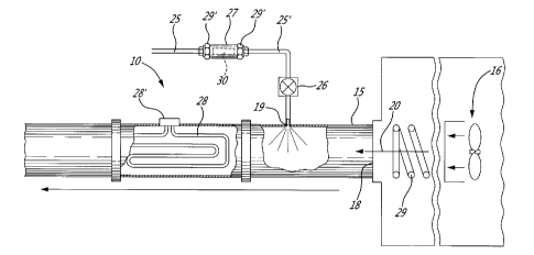
An air injection system for a hydro-massaging bath is described. An air convecting conduit is in communication with a plurality of injecting orifices formed in a peripheral wall of the bath. An air blower injects air under pressure in an entry opening of the air convecting conduit. A water spray injector is located downstream of the entry opening and upstream of the air injecting orifices to inject a spray of a predetermined volume of water in the injected air under pressure. A water supply conduit is connected to the water spray injector and has a flow regulating valve to regulate the volume of water spray injected in the heated air to saturate the air with water. A shut-off valve is provided in the water supply conduit, and a heater is disposed in the air convecting conduit downstream of the water spray injector and upstream of the air injecting orifices wherein heated, humidified air injected in the water contained within the bathtub does not produce a cool sensation on the body of a user person.


French Abstract

Un système dinjection dair pour une baignoire hydromassante est décrit. Un conduit de convection dair est en communication avec une pluralité dorifices dinjection formés dans une paroi périphérique de la baignoire. Une soufflante injecte de lair sous pression dans une ouverture dentrée du conduit de convection dair. Un injecteur de pulvérisation deau est situé en aval de louverture dentrée et en amont des orifices dinjection dair pour injecter un jet dun volume deau prédéterminé dans lair injecté sous pression. Un conduit dalimentation en eau est relié à linjecteur de pulvérisation deau et comporte une vanne de régulation de débit pour réguler le volume du jet deau injecté dans lair chauffé pour saturer lair avec de leau. Un robinet darrêt est prévu dans le conduit dalimentation en eau et un élément chauffant est disposé dans le conduit de convection dair en aval de linjecteur de pulvérisation deau et en amont des orifices dinjection dair, lair chauffé humidifié injecté dans leau contenue dans la baignoire ne produisant pas une sensation de froid sur le corps dune personne qui lutilise.

Claims

Note: Claims are shown in the official language in which they were submitted.


- 6 -
CLAIMS,
1. An air injection system for a hydro-massaging bath, said bath having a
bottom wall and peripheral side walls, a plurality of air injecting orifices
distributed at least
along some of said peripheral side walls, an air convecting conduit in
communication with
air injecting orifices, an air blower for injecting air under pressure in an
entry opening of
said air convecting conduit, a water spray injector in said air convecting
conduit
downstream of said entry opening and upstream of said air injecting orifices
to inject a
spray of a predetermined volume of water in said injected air, a water supply
conduit
connected to said water spray injector and having a flow regulating valve to
regulate the
volume of water spray injected in said air to saturate the air with water, a
shut-off valve in
said water supply conduit, a heater in said air convecting conduit, downstream
of said
water spray injector and upstream of said air injecting orifices, and control
means for
regulating a temperature of said heated saturated air, to be injected into
water contained in
said bath via said air injecting orifices, in the range of about 34°C
to 45°C.
2. An air injection system as claimed in claim 1 wherein said flow
regulating
valve is disconnectably secured in said water supply conduit.
3. An air injection system as claimed in claim 2 wherein said flow
regulating
valve has a filter cartridge removably retained therein, said water supply
conduit being a
water recirculating conduit having a pump to recirculate water from within
said bath.
4. An air injection system as claimed in claim 2 wherein said water supply
conduit is connected to a domestic water supply.
5. An air Injection system as claimed in claim 1 wherein said air blower is

provided with a heating element to preheat air injecting in said entry
opening.
8. An air injection system as claimed in claim 1 wherein said
predetermined
volume of water is between 4 GPH to 15 GPH suitable to completely saturate
said air
injected by said blower.

- 7 -
7. An air injection system as claimed in claim 1 wherein said air
blower is a
variable speed blower, and said control means regulating the speed of said
blower to
thereby regulate the pressure in said air convecting conduit.
An air injection system as claimed in claim 1 wherein said water spray
injector is constituted by a small air injecting orifice formed in a sidewall
of said air
convecting conduit and in communication with said water supply conduit, said
small air
injecting orifice having an orifice size of about 2 mm.
9. An air injection system as claimed in claim 1 wherein the shut-off
valve is a
solenoid valve connected in said water supply conduit downstream of said flow
regulating
valve.
10, An air injection system as claimed in claim 7 wherein said control
means is
a control device to regulate the temperature and pressure of hot saturated air
injected in
water contained in said bath, a thermostat in communication with said air
convecting
conduit to feed temperature signals to said control device, said blower being
a variable
speed blower; said control device controlling at least one or both of said
heater and said
variable speed blower to regulate the temperature of said heated saturated air
injected into
said water.
11. An air injection system as claimed in claim 1 wherein said air
injecting
orifices are formed by small holes in direct communication with said air
convecting conduit.
12. An air injection system as claimed in claim 1 wherein said air
injecting
orifices are adjustable injection nozzles of air injectors.
13. An air injection system as claimed in claim 1 wherein said heater is a
resistive heating element disposed in a section of said air convecting conduit
to quickly
heal and vaporize said saturated air.
14. An air injection system as claimed in claim 1 wherein said hydro-
massaging
bath is a therapeutic bathtub.

- 8 -
15. An air injection system for a hydro-massaging bath, said bath having a
bottom wall and peripheral side walls, a plurality of air injecting orifices
distributed at least
along some of said peripheral side walls, an air convecting conduit in
communication with
air injecting orifices, an air blower for injecting air under pressure in an
entry opening of
said air convecting conduit, a water spray injector in said air convecting
conduit
downstream of said entry opening and upstream of said air injecting orifices
to inject a
spray of a predetermined volume of water in said injected air, a water supply
conduit
connected to said water spray injector and having a flow regulating valve to
regulate the
volume of water spray injected in said air to saturate the air with water, a
shut-off valve in
said water supply conduit, and a heater in said air convecting conduit,
downstream of said
water spray injector and upstream of said air injecting orifices, said flow
regulating valve
being disconnectably secured in said water supply conduit.
16. An air injection system as claimed in claim 15 wherein said flow
regulating
valve has a filter cartridge removably retained therein, said water supply
conduit being a
water recirculating conduit having a pump to recirculate water from within
said bath.
17. An air injection system as claimed in claim 15 wherein said water
supply
conduit is connected to a domestic water supply.
18. Use of an hydro-massaging bath for an hydro-massaging treatment, said
bath having a bottom wall and peripheral side walls, a plurality of air
injecting orifices
distributed at least along some of said peripheral side walls, an air
convecting conduit In
communication with air injecting orifices, an air blower for injecting air
under pressure in an
entry opening of said air convecting conduit, a water spray injector in said
air convecting
conduit downstream of said entry opening and upstream of said air injecting
orifices to
inject a spray of a predetermined volume of water in said injected air, a
water supply
conduit connected to said water spray injector and having a flow regulating
valve to
regulate the volume of water spray injected in said heated air to saturate the
air with water,
a shut-off valve in said water supply conduit, and a heater in said air
convecting conduit,
downstream of said water spray injector and upstream of said air injecting
orifices, said
heated saturated air being injected into said bath via said air injecting
orifices during said
hydro-massaging treatment.

Description

Note: Descriptions are shown in the official language in which they were submitted.


CA 02745170 2011-06-30

-1-
AIR INJECTION SYSTEM FOR A HYDRO-MASSAGING BATH
TECHNICAL FIELD
The present invention relates to an air injection system for a hydro-
massaging bath to eliminate the effect of coolness on the body of a user
person immersed
in hot water within the bath and in close proximity to air injecting orifices.

BACKGROUND ART
It is well known to inject air in the hot water contained in a bathtub to
provide a turbulence of the water whereby a user person receives a massaging
therapy by
the turbulent water. A plurality of orifices are distributed in the side walls
of the bathtub in
areas where a water massage is required such as in the back wall and lower
side wall
areas of the bathtub. Various hydro massaging baths are known and such
comprise
adjustable nozzle assemblies mounted on the wall of a bathtub to discharge
high velocity
jets of water to impinge upon the body of a user person. However, when
injecting air within
the hot water, the user person is subjected to a sensation of coolness where
the air jets
impact its wet body. This sensation is the result of an adiabatic reaction
which is caused by
air which is relatively dry, and which enters in contact with the water. This
sensation is felt
even if the air is heated to about 60 C. Increasing the temperature of the air
is not the
solution to resolve the problem as this would burn a user person's skin.
Accordingly, the
prior art has opted to mix the air with recirculated water from the bathtub or
with heated
water such that the injectors comprise a large quantity of water mixed with
air.
Another problem of injecting air in the water to cause turbulence is that the
air cools the water in the bathtub prematurely because of the large surface
contact area of
turbulent water with the air. It is therefore desirable to eliminate this cool
sensation when
injecting air in a bathtub through air injecting orifices or air injectors.
In British Patent GB 2 224 203 published on May 2, 1990, there is disclosed
a spa bath in which an air/water mixture is injected via injectors into the
water contained
within the bath. In that patent, water is taken from the bottom of the bath,
heated in a
heater and the heated water is supplied to jets within a manifold through
which
compressed air is blown. The water is injected through venturi orifices which
cause water
to be sucked through the jets to form fine droplets which are then discharged
through the
injectors. The droplets of heated water humidify and heat the air immediately
before the
air/water mixture is injected into the bath, therefore reducing discomfort to
the user and
maintaining the water temperature in the bath at a desired level. There are
several


CA 02745170 2011-06-30

-2-
disadvantages of this method, one being that the injector assembly is very
expensive and
troublesome. In a system as described, it is likely that the injectors will
not all operate in a
uniform fashion due to variation in pressure along the injector line. The
clogging of the
venturi gaps due to the fact that the recirculating water entering the nozzles
may clog up
the nozzles due to the various products and impurities in the water,
particularly when water
is extracted from the bottom end of the bathtub. Such decalibrates the
operation of the
injectors. However, this reference confirms that hot bath water is subjected
to accelerated
cooling when the water is agitated in contact with ambient atmosphere and that
unless
water is heated to about 50 C, injected air entering the bath will feel cool
to a user person's
body close to the nozzle creating a "chill effect" caused by blown air in
contact with wet
skin.

SUMMARY OF INVENTION
It is a feature of the present invention to provide an air injection system
for a
hydro-massaging bath which substantially overcomes the above-mentioned
disadvantages
of the prior art.
Another feature of the present invention is to provide an air injection system
for a hydro-massaging bath having air injecting orifices to which is fed hot
humid air under
pressure such that when the hot humid air is injected in the bathtub the cool
sensation
against a user person's body is eliminated or substantially reduced.
Another feature of the present invention is to provide an air injection system
for a hydro-massaging bath wherein hot humid air is injected into the bathtub
through an
air distribution conduit in which is injected a waterspray to humidify air
under pressure and
wherein a heater is provided in the conduit to heat the hot humid air to a
desired
temperature for injection through air injecting orifices formed in the
peripheral side walls of
the bath.
Another feature of the present invention is to provide an air injection system
for a hydro-massaging bath wherein water injected within the pressurized air
in the air
convecting conduit is regulated by a pressure reducing valve containing a
removable
filtered cartridge to remove impurities from the spray of water injected in
the air to prevent
clogging of the injection orifices.
Another feature of the present invention is to control the temperature of hot
humid air injected in a hydro-massaging bath whereby to create a heat
sensation in the
area of the air jets provided in the peripheral side walls of the bath.


CA 02745170 2011-06-30

-3-
According to the above features, from a broad aspect, the present invention
provides an air injection system for a hydro-massaging bath. The bath has a
bottom wall
and peripheral side walls. A plurality of air injecting orifices are
distributed in at least some
of the peripheral side walls. An air convecting conduit is in communication
with the air
injecting orifices. An air blower is provided for injecting air under pressure
and in an entry
opening of the air convecting conduit. A water spray injector is provided in
the air
convecting conduit downstream of the entry opening and upstream of the air
injecting
orifices to inject a spray of a predetermined volume of water in the injected
air. A water
supply conduit is connected to the water spray injector and has a flow
regulating valve to
regulate the volume of water spray injected in the heated air to saturate the
air with water.
A shut-off valve is provided in the water supply conduit. A heater is provided
in the air
convecting conduit downstream of the water spray injector and upstream of the
air
injecting orifices.

BRIEF DESCRIPTION OF DRAWINGS
A preferred embodiment of the present invention will now be described with
reference to the accompanying drawings in which:
Figure 1 is a fragmented perspective view illustrating the construction of an
air injection system coupled to a side wall of a bathtub and in communication
with an air
convecting conduit molded within the side wall;
Figure 2 is a schematic illustration of the air injection system of the
present
invention;
Figure 3 is a simplified schematic side view showing modifications to the air
injection system of the present invention as coupled to a hydro-massaging
bathtub;
Figure 4A is a fragmented section view showing one embodiment of the air
injecting orifices distributed in the peripheral side walls of the bathtub;
and
Figure 4B is a view similar to Figure 4A but showing a further embodiment
wherein the air injecting orifices are provided with adjustable injection
nozzles.

DESCRIPTION OF PREFERRED EMBODIMENTS
Referring to the drawings and more particularly to Figures 1 to 3, there is
shown generally at 10 an air injection system for a hydro-massaging bath 11
constructed
in accordance with the present invention. A hydro-massaging bath also includes
indoor
and outdoor spas having a hybrid system. The bath 11 has a bottom wall 12 and
peripheral side walls 13. A plurality of air injecting orifices 14 are
provided and distributed


CA 02745170 2011-06-30
-4-

at least along some of the peripheral side walls 13. An air convecting conduit
15 surrounds
the air injecting orifices 14. Accordingly, when air under pressure by a
blower 16 is injected
within the air convecting conduit 15 air will enter under pressure into the
hot water 17
contained within the bathtub and create a turbulence in the water.
As more clearly shown in Figure 2, the blower 16 injects air under pressure
in an entry opening 18 of the air convecting conduit 15 and a water spray
injector 19
spaced from the entry opening 18 injects a spray of water within the
pressurized air flow
20. The spray injector 19 is positioned downstream of the entry opening 18 and
upstream
of the air injecting orifices 14.
The water spray injector 19 is provided water from the domestic water line
25 via a flow regulating valve 27 and a solenoid valve 26 whereby to regulate
the pressure
and/or volume of water sprayed into the air flow 20 to assure that the air is
fully saturated
with humidity.
As also shown in Figure 2, a resistive heating element 28 is mounted within
the air convecting conduit 15 downstream of the water spray injector 19 and
upstream of
the air injecting orifices 14 whereby to quickly heat and vaporize the
saturated air to a
desired temperature. As shown in Figure 2, a heating coil 29 or a further
resistive heating
element (not shown) may be interposed in the air flow path 20 between the
blower and the
entrance opening to pre-heat the injected air within the air convecting
conduit 15.
In Figures 1 and 2, it can be seen that the flow regulating valve 27 is
disconnectably secured in the water supply conduit 25 by lock nuts 29' to give
access to a
filter cartridge 30 housed within the flow regulating valve 27. The cartridge
30 filters
impurities from the water supply line 25. This is particularly useful, as
shown in Figure 3,
when the water supply line is a recirculating conduit 31 which recirculates
the water 17
from the bath 11 through a pump 32. The pump 32 draws the water from the
bottom of the
bath 11 through a conduit 33 and feeds it to the flow regulating valve 27. In
such an
arrangement the solenoid valve 26 would not be necessary as the controller 35
would
control the operation of the pump 32 to stop the flow of recirculating water.
As also shown in Figure 3, the controller 35 controls the blower 16, the
electrical supply terminal 28' of the resistive heating element 28 and the
solenoid valve 26
when a recirculating conduit 31 is not provided.
In order to completely saturate the air flow 20 it has been found that the
flow
regulating valve needs to be adjusted to inject between 4 GPH to 15 GPH of
water into the
air flow 20. By controlling the adjustment of the solenoid valve 26 the volume
of water
injected in the air flow can be controlled. The water spray injector 19 is
herein constituted


CA 02745170 2011-06-30

-5-
by a small air injecting orifice formed in a side wall of the air convecting
conduit 15 and has
an orifice size of about 2 mm. The controller 35 also controls the blower
speed 16 to
control the air flow displacement and therefore pressure of air injected in
the bath through
the air injecting orifices. Accordingly, the control circuit 35 can regulate
the temperature
and pressure of hot saturated air injected in the water 17 contained within
the bath 11.
A thermostat 36 is conveniently secured to the air convecting conduit 15 to
feed temperature signals to the control device 35 via its connection 37
whereby the control
device 35 can automatically make the necessary adjustments to regulate the
temperature
and saturation of the air under pressure in the air convecting conduit 15. The
temperature
of the heated saturated air, when injected into the water within the bath, is
in the range of
about 35 C to 45 C and at such temperature there is no harm to the skin of a
user person
bathing in the bath while the "chill effect" sensation is substantially
eliminated. In fact,
when the temperature is in the higher range, a sensation of warmer water is
felt on a user
skin without fear of burning the skin of the user person.
Referring to Figures 4A and 4B, there are shown two versions of the air
injecting orifices 14. As shown in Figure 4A, the air injecting orifice 14 is
simply a hole
formed in the peripheral wall 13 of the bathtub and in communication with the
air
convecting conduit 15. The size and dimension of this hole is described in
previous patents
of Bain Ultra and does not form part of the present invention. Also, as shown
in Figure 4B,
the air injecting orifices may be constituted by adjustable injection nozzles
38 disposed in
communication with the air convecting conduit 15. The bath 11 may be a
therapeutic
bathtub incorporating various therapeutic treatments such as lumino therapy,
hydro
therapy and thermal therapy. Another advantage of the air injection system of
the present
invention is that the water within the bathtub can stay hot longer and the
water is cleaner
and sterilized by the use of removable filter cartridges provided in the flow
regulating valve
such cartridges being accessible for replacement.
Another advantage of the present invention is that after use, the controller
can automatically engage a cleaning and drying cycle wherein the solenoid
valve 26 is
shut-off and the air blower is engaged whereby to flush out any residual
humidity within the
air convecting conduit 15 and the injectors to dry out the air convecting
conduit and injector
orifices. The heater 28 may also be actuated to accelerate the drying cycle if
the resistive
heating elements 29 within the blower are not sufficient.
It is within the ambit of the present invention to cover any obvious
modification of a preferred embodiment described herein provided such
modifications fall
within this scope of the appended claims.

Representative Drawing
A single figure which represents the drawing illustrating the invention.
Administrative Status

For a clearer understanding of the status of the application/patent presented on this page, the site Disclaimer , as well as the definitions for Patent , Administrative Status , Maintenance Fee  and Payment History  should be consulted.

Administrative Status

Title Date
Forecasted Issue Date 2018-09-25
(22) Filed 2011-06-30
(41) Open to Public Inspection 2012-12-30
Examination Requested 2016-06-29
(45) Issued 2018-09-25

Abandonment History

There is no abandonment history.

Maintenance Fee

Last Payment of $347.00 was received on 2024-03-14


 Upcoming maintenance fee amounts

Description Date Amount
Next Payment if standard fee 2025-06-30 $347.00
Next Payment if small entity fee 2025-06-30 $125.00

Note : If the full payment has not been received on or before the date indicated, a further fee may be required which may be one of the following

  • the reinstatement fee;
  • the late payment fee; or
  • additional fee to reverse deemed expiry.

Patent fees are adjusted on the 1st of January every year. The amounts above are the current amounts if received by December 31 of the current year.
Please refer to the CIPO Patent Fees web page to see all current fee amounts.

Payment History

Fee Type Anniversary Year Due Date Amount Paid Paid Date
Application Fee $400.00 2011-06-30
Maintenance Fee - Application - New Act 2 2013-07-02 $100.00 2013-06-03
Maintenance Fee - Application - New Act 3 2014-06-30 $100.00 2014-04-25
Maintenance Fee - Application - New Act 4 2015-06-30 $100.00 2015-06-01
Maintenance Fee - Application - New Act 5 2016-06-30 $200.00 2016-06-01
Request for Examination $800.00 2016-06-29
Maintenance Fee - Application - New Act 6 2017-06-30 $200.00 2017-04-18
Maintenance Fee - Application - New Act 7 2018-07-03 $200.00 2018-04-30
Final Fee $300.00 2018-08-14
Back Payment of Fees $300.00 2018-08-14
Maintenance Fee - Patent - New Act 8 2019-07-02 $200.00 2019-03-06
Maintenance Fee - Patent - New Act 9 2020-06-30 $200.00 2020-04-22
Maintenance Fee - Patent - New Act 10 2021-06-30 $255.00 2021-04-08
Maintenance Fee - Patent - New Act 11 2022-06-30 $254.49 2022-06-09
Maintenance Fee - Patent - New Act 12 2023-06-30 $263.14 2023-04-06
Registration of a document - section 124 $100.00 2023-09-29
Maintenance Fee - Patent - New Act 13 2024-07-02 $347.00 2024-03-14
Owners on Record

Note: Records showing the ownership history in alphabetical order.

Current Owners on Record
BAINS ULTRA INC.
Past Owners on Record
GESTION ULTRA INTERNATIONALE INC.
Past Owners that do not appear in the "Owners on Record" listing will appear in other documentation within the application.
Documents

To view selected files, please enter reCAPTCHA code :


To view images, click a link in the Document Description column. To download the documents, select one or more checkboxes in the first column and then click the "Download Selected in PDF format (Zip Archive)" or the "Download Selected as Single PDF" button.

List of published and non-published patent-specific documents on the CPD .

If you have any difficulty accessing content, you can call the Client Service Centre at 1-866-997-1936 or send them an e-mail at CIPO Client Service Centre.


Document
Description 
Date
(yyyy-mm-dd) 
Number of pages   Size of Image (KB) 
Abstract 2011-06-30 1 23
Description 2011-06-30 5 286
Claims 2011-06-30 2 80
Drawings 2011-06-30 3 111
Representative Drawing 2011-12-12 1 8
Cover Page 2012-12-12 1 43
Examiner Requisition 2017-07-17 4 230
Assignment 2011-06-30 4 157
Amendment 2018-01-16 10 419
Claims 2018-01-16 3 113
Correspondence 2011-07-20 1 16
Final Fee 2018-08-14 1 119
Final Fee 2018-08-14 3 110
Cover Page 2018-08-23 1 42
Correspondence 2012-03-13 3 101
Assignment 2011-06-30 5 196
Correspondence 2012-04-02 1 13
Request for Examination 2016-06-29 3 102