Note: Descriptions are shown in the official language in which they were submitted.
CA 02745253 2011-05-31
WO 2010/063736
PCT/EP2009/066175
1
Correction of Quadrature Errors
Field of the Invention
The present invention relates to the correction of quadrature errors
associated with digital communications systems, and in particular in a
wireless
transmit chain in which an up-converter and a down-converter both have a
direct
conversion architecture.
Background of the Invention
It is common for communications systems to have a digital part in which
a signal to be transmitted is processed before transmission and a further
digital
part in which received signals are processed after reception. Processing in
the
digital parts is typically carried out at base band, that is to say at the
frequency
band of signals before any offset for the purpose of transmission at a carrier
frequency; generally base band signals encompass zero frequency components,
i.e. direct current (DC) components. It is common for base band signals to be
represented by in-phase (I) and quadrature (Q) parts, that is to say, a
complex
representation. The processing may comprise such procedures as filtering,
modulation demodulation coding and decoding. It is generally necessary to
convert signals to and from the analogue domain for transmission and
reception,
and in the case of wireless systems, it is necessary to convert signals to and
from
an appropriate radio frequency.
There are various approaches to conversion of digital signals from base
band to and from a radio frequency. One approach is to up convert in the
digital
domain, so that complex base band signals are multiplied, that is to say
mixed,
by a digital local oscillator to produce an output at a higher frequency,
often
called an intermediate frequency (IF), that may then be converted to the
analogue domain by a digital to analogue converter. The intermediate frequency
signal is a real-only, rather than complex, signal. The analogue signal may
then
be further frequency translated to an appropriate frequency for transmission.
Similarly on reception, signals are converted from the analogue to digital
domains at an intermediate frequency, higher than base band, and then mixed
CA 02745253 2011-05-31
WO 2010/063736
PCT/EP2009/066175
2
down to in-phase and quadrature base band signals digitally. An advantage of
this approach is that the conversion from base band complex signals to
intermediate frequency signals and vice versa is carried out digitally and so
is
not subject to analogue errors that may cause differences in response between
in-phase and quadrature channels. However, a disadvantage is that digital to
analogue converters and analogue to digital converters have to operate at a
higher frequency than base band, in order to convert intermediate frequency
signals. Operating these components at a higher frequency means that the
components are costly, and potentially of lower performance in terms of
resolution than lower frequency digital to analogue converters and analogue to
digital converters.
An alternative approach to the conversion of digital signals from base
band to and from a radio frequency is generally termed direct conversion. In a
direct conversion architecture, the base band in-phase and quadrature signals
are
converted to and from analogue form at base band. On transmit, the analogue
in-phase and quadrature signals are then up-converted in the analogue domain
by analogue quadrature mixers. Preferably, the up-conversion is to the radio
frequency transmission frequency in one step, and as a result use of an
intermediate frequency is not required. Similarly, on reception, conversion of
received radio frequency signals is preferably directly to in-phase and
quadrature base band analogue signals, that are then converted to the digital
domain. An advantage of the direct conversion approach is that appropriate
digital to analogue and analogue to digital converters may be less costly, and
of
higher performance in terms of resolution. Also, the omission of the
intermediate frequency stage can lead to cost savings due to the need for
fewer
components. However, there is a potential penalty in that the in-phase and
quadrature signal paths involve analogue components such as filters that are
subject to variation of component values within a tolerance, so that the
analogue
properties of the in-phase and quadrature signal paths may vary from equipment
to equipment and over temperature.
CA 02745253 2011-05-31
WO 2010/063736
PCT/EP2009/066175
3
Errors that cause degradation from the perfectly orthogonal in-phase and
quadrature channels that exist in the digital domain are known as quadrature
errors, or IQ errors. In particular, there may be problems if there are
differential
errors between in-phase and quadrature channels. Differential errors between
in-phase and quadrature channels may cause, for example, spurious components
to be generated in a transmitter and spurious responses in a receiver. In
particular, a spurious response may be generated in the opposite side band to
that intended; for example, if a signal component is intended to be at a
higher
frequency than a local oscillator signal, then a differential error between in-
phase and quadrature components may lead to a spurious component appearing
at a lower frequency than that of the local oscillator signal.
Quadrature errors typically comprise voltage offsets, that is to say DC
offsets, differential gain characteristics between in-phase and quadrature
signal
paths, and phase error between in-phase and quadrature signal paths. A
conventional quadrature correction network 4 for the correction of such
quadrature errors is illustrated in figure 1; gain correction blocks Igain 5a
and
Qgain 5b are shown, as is a block 12 for the correction of phase errors
between
in-phase and quadrature paths, marked IQ phase, and blocks for the correction
of DC offsets I DC Offset 24a and Q DC Offset 24b.
However, quadrature errors, and in particular differential quadrature
errors, in both the upconversion and downconversion may be dependent on
frequency within the base band. For example, analogue filtering may introduce
such errors, particularly in anti-aliasing filters, due to the variation of
the values
of analogue components within component tolerance limits and with
temperature. Conventional correction networks cannot correct such errors.
The present invention addresses these disadvantages.
Summary of the Invention
In accordance with a first aspect of the invention, there is provided a
method of controlling a transmit chain. The transmit chain comprises a
correction network, a quadrature up-converter and a quadrature down-converter,
CA 02745253 2011-05-31
WO 2010/063736
PCT/EP2009/066175
4
the correction network being for correcting a frequency dependent quadrature
error between a transmission characteristic of an in-phase signal path and a
transmission characteristic of a quadrature signal path in a quadrature up-
converter, the quadrature up-converter being for use in the up-conversion of a
signal input to said correction network, and the quadrature down-converter
being for use in down-converting signals received thereby, wherein the up-
converter has an output coupled to said down-converter, the correction network
is configurable via a set of filter tap coefficient values, and the input
signal
comprises frequency components. In one embodiment the method comprises:
coupling an output signal from the output of the up-converter to said
quadrature down-converter;
using the down-converter to down-convert the coupled signal;
comparing the down-converted signal with the input signal; and
modifying the values of said filter tap coefficients on the basis of the
comparison,
whereby to correct said frequency dependent quadrature error by a
correction applied to a said frequency component, said correction being
dependent on the frequency of the said frequency component.
The benefit of controlling the transmit chain by updating the set of
values of filter tap coefficients on the basis of a comparison of a down-
converted signal with the input signal is that accurate control of the
correction
network may be achieved, specifically via a frequency dependent characteristic
of the correction network.
In one arrangement, the down-converted signal is compared with the
input signal so as to determine an error signal; this error signal is then
used,
together with the input signal, to modify the set of values of filter tap
coefficients. A training algorithm can then be used to update the values of
the
filter tap coefficients on the basis of the error signal and the input signal;
a
training algorithm is beneficial because it provides an efficient method of
updating the values of the filter tap coefficients.
CA 02745253 2011-05-31
WO 2010/063736
PCT/EP2009/066175
Preferably the method comprises providing the up-converter and the
down-converter with a local oscillator signal generated by a local oscillator
signal source, the local oscillator being operable in a plurality of
operational
states comprising:
5 a first
operational state in which the local oscillator is arranged to
input said local oscillator signal to the up-converter and the down-converter;
and
a second operational state in which the local oscillator is arranged
to apply a phase shift to the signal input to up-converter or the down-
converter
when the local oscillator is operating in the first operational state;
determining, for each operational state, an error signal by comparing the
down-converted signal with the input signal;
determining, for each operational state, an intermediate set of values of
filter tap coefficients on the basis of the error signal and the input signal;
and
updating current set of values of filter tap coefficients to produce an
updated set of values on the basis of a vector combination of the intermediate
sets of values with the current set of values.
As a result the corrector network may be controlled to correct quadrature
errors in the up-converter even in the presence of quadrature errors in the
down-
converter.
Advantageously, the down-converter further is in operative association
with a post-correction network arranged to correct a frequency dependent
quadrature error between in-phase and quadrature transmission paths in the
quadrature down-converter, the down-converted signal comprising frequency
components, and the post-correction network comprising a set of post-corrector
filter tap coefficients and configuration means for configuring values of said
set
of post-corrector filter tap coefficients, wherein the method further
comprises:
updating current values of post-corrector filter tap coefficients to
produce an updated post-corrector set of coefficients on the basis of a vector
combination of the intermediate sets of values of said filter tap coefficients
with
the current post-corrector set of coefficients; and
CA 02745253 2011-05-31
WO 2010/063736
PCT/EP2009/066175
6
using the updated post-corrector set of values to control the post-
correction network,
whereby to correct said quadrature error in the quadrature down-
converter by a correction applied to each said frequency component that is
dependent on the frequency of said frequency component. This provides a
means for controlling both a frequency dependent corrector network for an up-
converter and a frequency dependent corrector network for a down-converter.
Further, frequency dependent correction of a down-converter can be used as an
input to a predistortion controller for a power amplifier, thereby improving
the
operation of the predistortion controller.
The afore-mentioned functionality can be embodied as software, or
computer-readable code, encoded on a computer readable medium for use in
controlling the correction network, the up-converter and the down-converter in
the manner described above.
According to a second aspect of the invention there is provided a
transmit chain comprising:
a transmit path comprising:
a correction network for correcting a frequency dependent
quadrature error between in-phase and quadrature signal paths for the
transmission of an input signal, wherein the correction network
comprises an in-phase input port, a quadrature input port, an in-phase
output port and a quadrature output port and wherein each input port is
connected to each output port by a digital filter network, the digital filter
network comprising a set of filter tap coefficients and configuration
means for configuring values of said set of filter tap coefficients; and
a quadrature up-converter for up-converting the input signal; and
an observation path comprising:
a coupler for receiving a portion of the up-converted input signal;
and
a quadrature down-converter for down-converting the signal
received by the coupler;
CA 02745253 2014-01-31
7
the transmit chain further comprising a controller arranged to: determine an
error signal by comparing the down-converted signal with the input signal;
modify the set of values of filter tap coefficients on the basis of the error
signal
and the input signal; and use the updated set of values to control the
correction
network, whereby to correct said quadrature error by a correction applied to
each said frequency component that is dependent on the frequency of said
frequency component.
In accordance with a further aspect of the present invention, there is
provided a method of controlling a transmit chain comprising a correction
network, a quadrature up-converter and a quadrature down-converter, wherein
the correction network is configured to correct a frequency dependent
quadrature error between a transmission characteristic of an in-phase signal
path
and a transmission characteristic of a quadrature signal path in a quadrature
up-
converter, wherein the quadrature up-converter is configured to up-convert an
input signal input to the correction network, and wherein the quadrature down-
converter is configured to down-convert signals received thereby, wherein the
up-converter has an output coupled to the down-converter, wherein the
correction network is configurable via a set of filter tap coefficient values,
and
wherein the input signal comprises input frequency components within a base
band, the method comprising: coupling an output signal from the output of the
up-converter to the quadrature down-converter; down-converting, by the down-
converter, the coupled output signal; comparing the down-converted output
signal with the input signal; correcting the frequency dependent quadrature
error, comprising applying a first correction to at least a first frequency
component of the input frequency components, comprising modifying one or
more of the filter tap coefficient values based on said comparing, wherein the
first correction is dependent on a frequency of the at least first frequency
component; generating a local oscillator signal by a local oscillator; in a
first
operational state, providing the local oscillator signal to the up-converter
and the
down-converter; in a second operational state, providing the local oscillator
CA 02745253 2014-01-31
7a
signal to one of the up-converter and the down-converter, and providing a
phase
shifted version of the local oscillator signal to a remaining one of the up-
converter and the down-converter; determining, for each operational state, an
error signal by comparing the down-converted signal with the input signal;
determining, for each operational state, an intermediate set of filter tap
coefficient values on the basis of the error signal and the input signal; and
producing an updated set of filter tap coefficient values, comprising updating
a
current set of filter tap coefficient values on the basis of a vector
combination of:
the intermediate sets of filter tap coefficient values and the current set of
filter
tap coefficient values.
In accordance with a further aspect of the present invention, there is
provided a transmit chain comprising: a transmit path comprising: a correction
network for correcting a frequency dependent quadrature error between in-phase
and quadrature signal paths for transmission of an input signal having
frequency
components, wherein the correction network comprises an in-phase input port, a
quadrature input port, an in-phase output port and a quadrature output port,
and
wherein each input port is connected to each output port by a digital filter
network, the digital filter network comprising a set of filter tap
coefficients and
configuration means for configuring values of the set of filter tap
coefficients;
and a quadrature up-converter for up-converting the input signal; an
observation
path comprising: a coupler for receiving a portion of the up-converted input
signal; and a quadrature down-converter for down-converting the portion of the
up-converted input signal received by the coupler, a local oscillator operable
in a
first operational state and a second operational state, wherein the local
oscillator
is configured to: generate a local oscillator signal and provide the local
oscillator
signal to the up-converter; provide the local oscillator signal to the down-
converter when operating in the first operational state; provide a phase
shifted
version of the local oscillator signal to the down-converter when operating in
the
second operational state; a controller arranged to: determine an error signal
by
comparing the down-converted signal with the input signal; modify the values
of
CA 02745253 2014-01-31
7b
the set of filter tap coefficients based on the error signal and the input
signal;
and correct the frequency dependent quadrature error by applying a correction
to
at least one of the frequency components by controlling the correction network
using the updated set of values, wherein the correction is dependent on the
frequency of the at least one of the frequency components.
More specifically, according to one aspect there is provided a correction
network for correcting a frequency dependent quadrature error between a
transmission characteristic of an in-phase signal path and a transmission
characteristic of a quadrature signal path, said quadrature signal path being
for
the transmission of in-phase and quadrature parts of a signal, wherein the
correction network comprises an in-phase input port, a quadrature input port,
an
in-phase output port and a quadrature output port, wherein each input port is
connected to each output port by a digital filter network, the digital filter
network comprising a set of filter tap coefficients and configuration means
for
configuring values of said set of filter tap coefficients.
According to a further aspect, the present invention provides a correction
network for correcting a frequency dependent quadrature error between a
transmission characteristic of an in-phase signal path and a transmission
characteristic of a quadrature signal path, wherein the in-phase signal path
is for
transmission of in-phase portions of a signal having frequency components, and
wherein the quadrature signal path is for transmission of in-quadrature
portions
of the signal, wherein the correction network comprises an in-phase input
port, a
quadrature input port, an in-phase output port and a quadrature output port,
wherein each input port is connected to each output port by a digital filter
network, the digital filter network comprising a set of filter tap
coefficients and
configuration means for configuring values of the set of filter tap
coefficients,
wherein the digital filter network comprises: a first digital filter
connecting the
in-phase input port to the in-phase output port; a second digital filter
connecting
the in-phase input port to the quadrature output port; a third digital filter
connecting the quadrature input port to the in-phase output port; and a fourth
CA 02745253 2014-01-31
'
7c
digital filter connecting the quadrature input port to the quadrature output
port,
wherein each digital filter comprises a respective subset of filter tap
coefficients
of the set of filter tap coefficients, and respective configuration means for
configuring respective values of the respective subset of filter tap
coefficients.
The advantage of connecting each input port to each output port by a
digital filter network comprising a set of filter tap coefficients and having
configuration means for configuring values of said set of filter tap
coefficients is
that frequency dependent quadrature impairments, for example due to the
analogue components of a quadrature up-converter or down-converter, may be
corrected by suitable control of the coefficients.
In one embodiment the digital filter network comprises: a first digital
filter connecting the in-phase input port to the in-phase output port;
CA 02745253 2011-05-31
WO 2010/063736
PCT/EP2009/066175
8
a second digital filter connecting the in-phase input port to the
quadrature output port;
a third digital filter connecting the quadrature input port to the in-phase
output port; and
a fourth digital filter connecting the quadrature input port to the
quadrature output port,
wherein each digital filter comprises a respective set of filter tap
coefficients and respective configuration means for configuring values of said
respective set of filter tap coefficients.
Each digital filter can be embodied as a finite impulse response filter,
which is advantageous because a finite impulse response filter may be
controlled, by means of suitably selected coefficients, to provide a good
approximation to the frequency characteristics of quadrature impairments.
Alternatively, each digital filter can be embodied as a polynomial
structure based on a Volterra series, which is advantageous because such a
filter
provides a very good cancellation of quadrature impairment components.
Brief Description of the Drawings
Figure 1 is a schematic diagram showing a conventional quadrature
correction network;
Figure 2 is a schematic diagram showing frequency dependent pre-
correction and frequency dependent post correction controlled by the
comparison of a down converted signal with an input signal according to an
embodiment of the invention;
Figure 3 is a schematic diagram showing a frequency dependent
correction network according to an embodiment of the invention;
Figure 4 is a schematic diagram showing a frequency dependent
correction network according to an embodiment of the invention followed by
typical network impairments as an illustration of the operation of an
embodiment of the invention;
CA 02745253 2011-05-31
WO 2010/063736
PCT/EP2009/066175
9
Figure 5 is a schematic diagram showing a digital filter component of a
frequency dependent correction network according to an embodiment of the
invention;
Figure 6 is a schematic diagram showing a controller for a frequency
dependent pre-correction network and a frequency dependent post-correction
network according to an embodiment of the invention;
Figure 7 is a schematic diagram showing frequency dependent pre-
correction and frequency dependent post correction according to an embodiment
of the invention;
Figure 8 is a schematic diagram showing frequency dependent pre-
correction according to an embodiment of the invention;
Figure 9 is a schematic diagram showing detail of a controller for a
frequency dependent pre-correction network according to an embodiment of the
invention;
Figure 10 is a schematic diagram showing conventional pre-correction
and post-correction networks controlled by the optimisation of expected
properties of a down converted signal; and
Figure 11 is a schematic diagram showing frequency dependent pre-
correction and frequency dependent post correction as according to a yet
further
embodiment of the invention.
Detailed Description of the Invention
In general, the present invention is directed to methods and apparatus for
for correcting quadrature errors in communications systems.
By way of example an embodiment of the invention will now be
described in the context of a transmit chain of a wireless system, that is to
say a
series of components in the transmit section of a wireless system, in which a
digital signal is up-converted in a direct conversion transmit chain and in
which
a sample of the transmitted signal is down-converted in a direct conversion
receiver for reception by an observation receiver. The observation receiver
may
be used for the control of a pre-distortion function applied to the digital
signal
CA 02745253 2011-05-31
WO 2010/063736
PCT/EP2009/066175
before up-convertion, to pre-correct for a non-linear response of a power
amplifier. However, it will be understood that this example is for
illustration
only and the invention is not limited to use in wireless systems or for
systems
involved with pre-distortion of a non-linear amplifier.
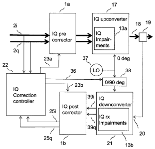
5 Figure 2 shows a first embodiment of the invention. A digital base
band
signal with in-phase components 2i and quadrature components 2q is input to a
pre-corrector la and then passed to the direct conversion IQ up-converter 17.
The IQ up-converter 17 comprises digital to analogue converters for the in-
phase and quadrature components and the analogue signals so generated are
10 passed via low-pass filters to a quadrature mixer for upconversion.
The
analogue paths inadvertently introduce quadrature errors, also called IQ
impairments 13a, in particular differential errors between in-phase and
quadrature components that vary as a function of frequency within the base
band. The up-converted signal 18 is output via a coupler 19, typically for
input
to a power amplifier for amplification in preparation for transmission from an
antenna. The IQ pre-corrector la is controlled by IQ correction controller 22,
specifically via control signals 23a in such a way as to reduce the effects of
the
IQ impairments 13a.
The coupler 19 couples a sample of the output 18 of the up-converter 17
and applies the sample to the input 20 of an IQ direct conversion down-
converter 21, which may be termed an observation receiver. The IQ down-
converter 21 comprises a quadrature mixer that has as outputs analogue in-
phase
and quadrature paths that pass through analogue anti-alias filters to a pair
of
analogue to digital converters (not shown). The separate analogue paths
inadvertently introduce quadrature errors, and similarly to the transmit path,
these impairments are particularly problematic when there are differential
errors
between in-phase and quadrature components that vary as a function of
frequency within the base band.
The digital in-phase and quadrature signal components 39i and 39q that
are produced by the downconverter 21 are passed to the IQ post corrector lb,
that is controlled by the IQ correction controller 22 via control signals 23b
in
CA 02745253 2011-05-31
WO 2010/063736
PCT/EP2009/066175
11
such a way as to reduce the effects of the IQ impairments 13b in the receive
path.
The IQ correction controller 22 compares the input signal components 2i
and 2q with the signal components 25i and 25q that are output after the after
IQ
post corrector lb that originate from signals received by the receive chain,
that
is to say by the observation receiver. The IQ correction controller 22
controls
the pre-corrector la and post-corrector lb via signals 23a, 23b such that the
error between the input signal components 2i, 2q and the received signal
components 25i, 25q is minimised. In addition the IQ controller, or possibly
another controller (not shown), controls the relative phase between a local
oscillator signal applied to the IQ up-converter 17 and that applied to the IQ
down-converter 21. In one arrangement, suitable controlling components are
shown schematically as parts 37 and 38, whose function will now be described.
Typically the relative phase between the signal produced by the local
oscillator 37 and the IQ up-converter 17 and the signal produced by the local
oscillator 37 and the IQ down-converter 21 is controlled between two states
differing by 90 degrees. Comparison of measurements made for each state
allows the IQ pre-corrector la to be corrected for IQ impairments in the up-
converter 17 and the IQ post-corrector lb to be corrected for IQ impairments
in
the down-converter 21. Typically the signal output from a local oscillator 37
is
split and one part is fed to the up-converter without a phase shift and the
other
part is phase shifted by nominally 0 or 90 degrees alternately and fed to the
down-converter. It is not necessary for the phase shift to be exactly 90
degrees,
since in principle any phase difference should allow the system to resolve the
correction needed for the pre-corrector from that needed by the post-
corrector.
It is preferable not to change the phase shift of the signal fed to the up-
converter,
since this phase shift would be imposed on the transmitted signal as an
unwanted phase modulation. It should be noted that the variable phase shift
may alternatively be imposed on the liffl( from the coupler 19 to the input to
the
IQ down-converter 21. This, however, requires that the phase shifter be
broader
band than if the phase shifter were placed in the local oscillator path, since
the
CA 02745253 2011-05-31
WO 2010/063736
PCT/EP2009/066175
12
signal coupled by the coupler 19 may be modulated whereas the local oscillator
signal typically is not.
Figure 3 shows the structure of a frequency dependent quadrature
correction network according to the invention, as may be used for either a pre-
correction network la or a post-correction network lb. In-phase digital
components enter at 2i and quadrature digital components enter at 2q. The in-
phase components are split into two paths; one path passes through a digital
filter 6a to a combiner 8a and thence to the in-phase output 3i. The other
path
passes through digital filter 6b to combiner 8b and thence to the quadrature
output 3q. The transmission characteristic of digital filter 6a may be
represented
by 1+A to indicate that the signal passes largely unaltered except for a small
factor A, that may be frequency dependent. For filter 6b, the transmission
characteristic may be represented by B to indicate that the signal is
attenuated by
a factor B, that may be frequency dependent. Typically both A and B are much
less than 1, preferably less than 0.1.
Per the in-phase components, the quadrature components are split into
two paths; one path passing through a digital filter 6d to combiner 8b and
thence
to the quadrature output 3q. The other path passes through digital filter 6c
to
combiner 8a and thence to the in-phase output component 3i. The transmission
characteristic of digital filter 6d may be represented by 1+D to indicate that
the
signal passes largely unaltered except for a mall factor D, that may be
frequency
dependent. For filter 6c, the transmission characteristic may be represented
by
C to indicate that the signal is attenuated by a factor C, that may be
frequency
dependent. Typically both C and D are much less than 1, and preferably less
than 0.1.
Figure 4 illustrates how a correction network, in this case used as a pre-
correction network 1 a, corrects for impairments 13. It can be seen that the
impairments are modelled as a network with a similar topology as the
correction
network 1 a. In-phase components 2i pass through filter 6a and are multiplied
by
transmission factor 1+A, and then pass through the impairment characteristic
14a multiplied by a transmission factor 1 + Ai. Here the terminology Ai is
CA 02745253 2011-05-31
WO 2010/063736
PCT/EP2009/066175
13
simply used to indicate that Ai is an impairment factor, not that it is an in-
phase
or imaginary factor. It will be apparent that square terms will be generated,
but
for small A, B, C and D the square terms are negligible.
Referring to figure 4, considering first the impairments, it can be seen
that an in-phase signal component 3i entering the network simulating IQ
impairments 13, is multiplied by a factor (1 + Ai) and arrives at the output
of the
network simulating IQ impairments 13 at output port 16i. It can be seen that a
component of the quadrature signal component 3q is multiplied by Ci in the
network simulating IQ impairments 13 and is added in an addition block 15a to
the in-phase component that was multiplied by the factor (1+ Ai) to appear at
the in-phase output 16i.
In order to correct for these impairments to a first approximation, a
corrector network 1 a is provided. An in-phase component 2i is multiplied by
the factor (1+A), and a quadrature component 2q is multiplied by a factor C
and
added to the multiplied in-phase component and passed to the input 3i to the
network simulating IQ impairments 13.
For small A and Ai, it can be shown that the impairment factor Ai may
be substantially removed when A = -Ai. It can be seen by reference to figure 4
that square terms arise since, for example in the two cascaded in-phase signal
paths through blocks 6a and 14a, the transmission factor will be (1+A)(1-A) =
1
-A2.
Similarly, for small C and Ci, the spurious quadrature component
passing through block 14c with transmission factor Ci is substantially
cancelled
by the component of 2q passing through block 6c of the correction network 1 a
with transmission factor C, when C= -Ci.
If A, B, C and D are less than 0.1 then the square terms will be less than
1% in voltage terms, that is to say -40dB in power terms.
Similarly, the in-phase component passing through B will substantially
cancel the spurious component Bi, if B= -Bi and B is small, i.e. much less
than
1. It will also be apparent that if D= -Di the impairments in block 14d may
also
be cancelled, again when D and C are small.
CA 02745253 2011-05-31
WO 2010/063736
PCT/EP2009/066175
14
It should be understood that a similar principle will apply to a post-
corrector network that follows an impairment.
As has already been mentioned, the correction of differential errors in
the transmission characteristic between in-phase (I) and quadrature (Q)
channels
is of particular importance. It is thus of practical importance that
impairments
that cause differential errors are cancelled, but it may be acceptable for the
combination of the impairment and the correction to produce transmission
characteristic that, although not the same as the transmission characteristic
without the impairment, is nevertheless the same on I and Q channels. That is
to
say that, in the case of the illustration of figure 4, the desired outcome is
not
necessarily a situation in which the I and Q channels each have a transmission
characteristic of 1. It may also be an acceptable outcome that both I and Q
channels have some other transmission characteristic, provided that the
characteristic on each is the same. The operation of the control loop will
automatically produce optimum transmission characteristics for the filters in
a
correction network; it should be understood that the optimum solution will not
necessarily be the application of a correction that simply returns the
transmission characteristics to a state that would have existed in the absence
of
quadrature impairments. Indeed, the operation of the control loop may
potentially improve the operation of the system beyond simply removing
differential errors between in-phase and quadrature channels, if the factor
that is
optimised by the control loop is changed in a beneficial manner by the
improvement. For example, a flattening of gain of both in-phase and quadrature
channels may be achieved by the operation of the control loop.
Figure 5 shows components of a typical digital filter 6a, 6b, 6c or 6d
shown in Figure 4. Digital signal components 2i are passed to a tapped delay
line comprising a series of delay elements 9a, 9b that each delay the signal
components by a time T; this delay time T may be the sampling period of the
digital signals. After each delay element, part of the signal is tapped off
and
multiplied by a filter coefficient or weight Cn. The weighted components are
then summed in a summing component 11 and passed to the output 7a. Filter
CA 02745253 2011-05-31
WO 2010/063736
PCT/EP2009/066175
coefficients are shown as factors Cl, C2.. Cn. This structure constitutes a
conventional finite impulse response (FIR) filter. The coefficients may be
linear
factors, and are controllable by the correction controller 22 in order to best
cancel the impairments by matching the frequency response of the relevant
5 component of the impairment. It is also possible that each tap may,
in addition
to linear factors, have controllable coefficients that operate on the squares,
cubes
or other non-linear functions of the tapped signal. Such a structure may be
referred to as a representation of a Volterra series.
Figure 6 shows the IQ correction controller 22 in more detail. Input in-
10 phase 2i and quadrature 2q components that are input to the
controller and are
compared with the in-phase 25i and quadrature 25q components from the
observation receiver as has been already mentioned. In order to correct for
phase shifts and amplitude imbalances occurring due to the practical
implementation of a system, it is necessary to align the signal components
from
15 the input relative to those from the observation receiver before
carrying out a
comparison to generate an error signal. The reason for this is that the error
signal should represent the effect of the contribution of the IQ impairments,
rather than effects due to other circuit elements. For control of the pre-
corrector
coefficients, an align and compare block 26a operates to align the received
signals 25i, 25q in phase with the input signal components 2i, 2q. For control
of
the post-corrector coefficients, the align and compare block 17b operates to
align the input signal 2i, 2q in phase with the received signal components
25i,
25q.
Considering first the operation of the controller 22 to update the pre-
corrector error coefficients, the align and compare block 26a generates a
reference output refl 27a, that represents the input signal component, and an
error output error 1 28a that represents the difference between the aligned
signal
from the observation receiver with the input signal component. The signals ref
1 and errorl are passed to the train error coefficients functional block 29a.
This
block maintains a model of the corrector network in terms of topology and the
training involves adjusting the error coefficients such that, when applied to
the
CA 02745253 2011-05-31
WO 2010/063736
PCT/EP2009/066175
16
reference, the model of the corrector network produces the error signal. This
may be done by conventional techniques. A suitable technique involves
solution of a set of simultaneous equations relating the input to the error
signal
to produce a set of coefficients. Typically this will be repeated many times
and
a least mean squares method will be applied to produce an optimum result from
the multiple measurements. A similar process is used to train the error
coefficients for the post corrector using the train error coefficients
functional
block 29b.
As has been already mentioned, the training process described cannot
distinguish between the coefficients required for the pre-corrector and those
required for the post-corrector; to accommodate this ambiguity the training
can
be performed in two stages: initially with the local oscillator signals for
the up-
converter and the down-converter in a first relative phase state, and
subsequently with the local oscillator signals in a second relative phase
state,
typically 90 degrees different from the first relative phase state.
Considering first the control of the pre-corrector coefficients, the switch
30a operating on the output of the train error coefficients functional block
29a
directs the error coefficients to be stored for local oscillator phase state 0
at store
31a and directs those error coefficients calculated at local oscillator phase
state
90 (that is, 90 degrees different than phase state 0) to be stored separately
at
store 31b. The sum of the two stores of error coefficients, indicated
schematically by part 32, is then used as an update to be added to the pre-
corrector coefficients. The pre-corrector coefficients are iteratively updated
by
adding the sum of the stored error coefficients 32 trained in the two local
oscillator states, in order to substantially cancel the IQ impairments.
The post corrector coefficients are updated by a similar process via parts
31c, 31d and 33, but taking the difference between the stored error
coefficients
for the two local oscillator states rather than the sum thereof. If a phase
shift is
introduced into the alignment process at one local oscillator phase
relationship
and not another, then a corresponding phase shift should be applied to the
stored
error coefficients before the sum or difference operations, in order to
CA 02745253 2011-05-31
WO 2010/063736
PCT/EP2009/066175
17
compensate for the phase shift. The combined process of phase shift and sum
operation, and similarly the combined process of phase shift and difference
operation, may be termed vectorial combinations.
Figure 7 illustrates the system of figure 6 applied to a transmit chain
employing pre-distortion to correct for non-linearities in a power amplifier
40.
It is particularly advantageous to use embodiments of this invention in
combination with a system for linearising the response of a power amplifier by
pre-distortion. Wireless communication devices, such as base stations and
terminals, have a transmit chain which includes a power amplifier to amplify a
modulated signal to a high power level for transmission over a wireless
channel.
It is known that elements in the transmit chain can introduce distortion to
the
transmitted signal and therefore there have been various proposals to
compensate for distortion. One such proposal is a pre-distortion architecture
where a low power modulated signal is pre-distorted in a manner which will
compensate for non-linear effects of a power amplifier, before being applied
to
the input of the power amplifier. The combination of the pre-distortion
applied
to the input signal, and the (inevitable) non-linear distortion applied to the
input
signal by the power amplifier, result in a substantially distortion-free
output
signal.
Typically, an adaptive pre-distortion architecture applies pre-distortion
in the digital domain before up-conversion. Pre-distorted signals for in-phase
and quadrature channels are digitally created at base band, are separately
converted to analogue, and are then directly up-converted by applying them to
the in-phase and quadrature branches of a direct conversion up-converter, also
known as an IQ up-converter. A portion of the up-converted output signal is
fed
back to a comparison function to control the pre-distortion system. This
feedback path is known as an observation receiver, and can either down-convert
a sampled portion of the up-converted output signal to an Intermediate
Frequency (IF), or can down-convert a sampled portion of the up-converted
output signal directly to base band.
CA 02745253 2011-05-31
WO 2010/063736
PCT/EP2009/066175
18
As has been mentioned, the direct conversion approach may be
advantageous in terms of economical implementation, but may suffer from the
effects of differential errors in the in-phase and quadrature signal paths.
The
direct conversion approach has the particular advantage that the local
oscillator
for the downconversion and the upconversion operate at the same frequency and
so use may use the same synthesiser, avoiding the risk of spurious frequency
frequency generation involved if a direct conversion architecture were used
for
the up-converter with an intermediate frequency architecture used for the down-
converter.
However, the inherent quadrature errors have inhibited the use, and
effectiveness, of a direct conversion architecture in the observation receiver
path. Methods
to correct for non-frequency dependent up-converter
imperfections are known, and involve use of a conventional quadrature error
corrector as shown in figure 1; however these do not include additional
quadrature impairments that are required to correct for these imperfections.
If
the observation receiver uses a direct conversion architecture then quadrature
errors will be introduced in the observation receiver. Even once the
quadrature
errors in the up-converter have been compensated for, the errors in the down-
converter impair the observation signal used to control the power amplifier
predistortion and limit the effectiveness of the amplifier predistortion
correction
loop. Accordingly, it is necessary to correct for errors introduced by the up-
converter and down-converter. The system illustrated in figure 8 is designed
to
achieve this.
It can be seen that a power amplifier predistortion controller 44 receives
input signal components 45i, 45q and also the corrected signal components 25i,
25q from an observation receiver, corrected by an IQ post-corrector lb. The
power amplifier predistortion controller 44 uses these input components to
generate a predistortion characteristic to apply to the input signal in the PA
pre-
distort block 43, to produce the input components 2i, 2q to the IQ pre-
corrector
stage la. The pre-corrected signal component is then applied to the IQ up-
converter 17 and the up-converted signal component passes though coupler 19
CA 02745253 2011-05-31
WO 2010/063736
PCT/EP2009/066175
19
to power amplifier 40 and then passes through a second coupler 41 for
transmission. Switch 42 directs the signal components to the IQ down-converter
21 from the coupler 19 that is located upstream of the power amplifier (PA) 40
when the IQ correction controller is operating, and directs signal components
from coupler 41 to the down-converter 21 when the PA predistort controller 44
is operating. This is because the PA controller 44 operates to minimise the
difference between the input to the transmit chain 45i, 45q (the input to the
PA
predistort block 43) and the output of the power amplifier (as measured at the
output 25i, 25q of the IQ post corrector lb by appropriate setting of the
switch
42), whereas the IQ controller correction controller 22 operates to minimise
the
difference between the input 2i, 2q to the IQ pre-corrector 1 a and the output
of
the IQ up-converter 17 (also as measured at the output 25i, 25q of the IQ post
corrector lb with appropriate setting of switch 42).
Figure 8 illustrates that the system of figure 2 may operate without
applying post-correction, that is without calculating or applying coefficients
to a
post-corrector lb. Figure 9 shows an IQ correction controller 22 controlling
the
IQ pre-corrector 1 a only. It has been found that the pre-correction
coefficients
of IQ pre-corrector la can be trained to cancel the IQ impairments 13a in the
up-
converter even if the post-corrector is absent. Generally it is beneficial,
but not
essential, to implement the post-corrector lb in order to speed up the
convergence of the IQ correction control loop. It is also beneficial to
correct the
output of the IQ down-converter when used with a power amplifier predistortion
control loop, in order to optimise the performance of the loop.
Figure 10 illustrates in block diagram form a system in which
conventional pre-correction 4a and post-correction 4b networks are controlled
by a controller 60 on the basis of the optimisation of expected properties of
a
down converted signal, as disclosed in co-pending US patent application
11/962432. This
application addresses the correction of non-frequency
dependent quadrature errors in a system with a direct conversion up-converter
and an observation receiver using a direct conversion down-converter
architecture. A technique is disclosed that may distinguish between quadrature
CA 02745253 2011-05-31
WO 2010/063736
PCT/EP2009/066175
errors in the up-converter and those in the down-converter, by the use of
measurements made with the up-converter and down-converter local oscillators
in a first phase relationship, and then further measurements with the up-
converter and down-converter local oscillators in a second phase relationship,
5 typically 90 degrees different from the first phase relationship. The
measurements are of properties of signals received in the observation receiver
and that are compared with expected properties of the signal. For example, the
long term correlation between in-phase and quadrature components may be
expected to be zero for an ideal signal, as may be the DC voltage component.
10 Quadrature errors in the up-converter and down-converter paths are
then
separately corrected using correction networks that apply a correction that is
nominally the same irrespective of frequency within the base band. Such
corrections typically comprise correction of voltage offsets, that is to say
DC
offsets, differential gain characteristics between in-phase and quadrature
signal
15 paths, and phase error between in-phase and quadrature signal paths.
A
conventional quadrature correction network 4 may be used, such as that
illustrated in figure 1.
However, there may be errors, and in particular differential errors, in
both the up-conversion and down-conversion that are that dependent on
20 frequency within the base band. For example, analogue filtering may
introduce
such errors, particularly in anti-aliasing filters, due to the variation of
the values
of analogue components within component tolerance limits and with
temperature. Conventional correction networks such as that illustrated in
figure
1 cannot correct such errors.
Also, measurements based on long-term averages of expected properties
of received signals are inherently slow and may not provide sufficient loop
gain
and stability to correct quadrature errors to a high degree of accuracy.
Advantageously the conventional system of figure 10 may be used in
conjunction with embodiments of the present invention already described, in
particular as illustrated in figures 6 and 7, to address the correction of
frequency
dependent quadrature errors, as illustrated in figure 11. Figure 11 shows that
CA 02745253 2011-05-31
WO 2010/063736
PCT/EP2009/066175
21
frequency dependent 1 a and conventional 4a pre-correction networks may be
cascaded, as may frequency dependent lb and conventional 4b post-correction
networks. It may be beneficial to remove gross errors using a conventional
quadrature correction circuit such as that of figure 1 in order to improve the
operation of the frequency dependent pre-corrector control loop. The
conventional pre-correction circuit may be controlled to optimise expected
properties of the down converted signal as already described by reference to
figure 10. In particular, it is beneficial to correct DC offsets in this
manner,
since a conventional quadrature correction circuit is well suited to this
function
and a control loop based on the expected properties of an observed signal is
particularly effective for the control of a conventional IQ correction
circuit.
It will be apparent that embodiments of the invention may be applicable
to wired systems such as cable TV in addition to wireless systems.
The above embodiments are to be understood as illustrative examples of
the invention. It is to be understood that any feature described in relation
to any
one embodiment may be used alone, or in combination with other features
described, and may also be used in combination with one or more features of
any other of the embodiments, or any combination of any other of the
embodiments. Furthermore, equivalents and modifications not described above
may also be employed without departing from the scope of the invention, which
is defined in the accompanying claims.