Note: Descriptions are shown in the official language in which they were submitted.
CA 02745387 2016-05-18
'78041-33
WAVE ENERGY CONVERTER and POWER TAKE OFF SYSTEM
BACKGROUND OF THE INVENTION
This invention relates to Power Take-Off (PTO) apparatus for use with a
wave energy converter (WEC) and, in particular, to an improved PTO system
employing reciprocating linear motion.
In general, WECs are devices which convert mechanical energy present in
ocean waves to electrical energy or any other suitable form of energy. WECs
may take Many different forms. The present invention is highly suitable for
use
with WECs which convert the wave energy motion into a reciprocating motion
which is substantially linear.
Fig. 1 shows a prior art WEC in which the PTO includes a hydraulic
system for driving a generator/motor. The WEC shown in Fig. 1 includes two
main components: a toroid-shaped float (1) and a cylindrical-shaped spar (2),
with the float (1) being disposed around the spar (2). In this configuration,
the
float may be designed to be neutrally buoyant whereby its waterline is
substantially centered at about halfway of its height. The hydrodynamic design
of
the system is such that the spar (2) remains substantially stationary, or at
least
its dynamic behavior is dominated by its inertia; while the float (1)
substantially
CA 02745387 2016-05-18
78041-33
'
follows the motion of the waves (1A) (i.e., is generally in phase with the
waves). In
addition to the hydrodynamic design, the spar (2) may also be held stationary
by
being anchored (1B) to the sea bed (1C) through a flexible joint (1D) (as
shown in
Fig. 1) or it may be held relatively stationary with the aid of a heave plate
which is
attached near the bottom of the spar (2).
The relative force and motion between the float (1) and spar (2) is converted
into electrical energy by means of a PTO (10) connected between them. In Fig.
1, the
PTO includes a hydraulic system including a hydraulic motor (1E) coupled via a
shaft
(1F) to a generator (1G) to produce electrical energy for a load (1H). Due to
the
lo relatively low frequency of the waves, the corresponding electrical
signals tend to be
of low frequency which is very inefficient. To overcome this problem various
gearing
mechanisms may be introduced to increase the frequency of the electrical
signals
being produced. However, known gearing mechanisms tend to require substantial
maintenance and replacement and tend to be inefficient and unreliable.
Other problems exist with known systems in the efficient and reliable
conversion of wave energy into electrical energy.
It is an object of the present invention to overcome many of the known
problems and to provide a PTO apparatus which can convert the relative force
and
motion of the float and spar into electrical energy in an efficient and
reliable manner.
SUMMARY OF THE INVENTION
A wave energy converter (WEC) embodying the invention includes a float
and a spar, with the float intended to move, generally, in phase with the
waves
2
CA 02745387 2011-06-01
WO 2011/062576
PCT/US2009/006272
and the spar intended to move, generally, out of phase with the float. The
relative motion between the float and spar, due to waves, is converted to
linear
motion generating forces applied to a power take off device (PTO). The PTO is
preferably, but not necessarily, located within the spar. That is, the PTO may
be
located externally to the spar; but it then becomes subject to corrosive
action of
the water.
A PTO embodying the invention includes a rack and pinion mechanism
which drives a high-torque, multi¨pole, typically more than 8 poles, permanent
magnet generator (PMG) to produce an electrical signal of relatively high
frequency relative to the frequency of the waves and the basic motion of the
rack
and pinion mechanism. In accordance with the invention, the frequency of the
voltage produced by the generator will be at least an order of magnitude
greater
than the frequency of the waves. This permits the fabrication of a more
reliable
and efficient PTO system which does not require a gearing mechanism, other
than the rack and pinion, to increase the speed of rotation and the frequency
of
the voltage produced by the PTO.
In accordance with an aspect of the invention, the pinion is integrally
connected to the shaft of the generator and the shaft is connected to, and
drives,
the rotor of the generator.
In accordance with another aspect of the invention, the rack and pinion
mechanism is located within the spar and is driven by a thrust (push) rod
which is
responsive to the relative motion between the spar and the float and which
passes through an aperture in the spar. At the site of the aperture, a
compliant
3
CA 02745387 2011-06-01
WO 2011/062576
PCT/US2009/006272
sealing mechanism is formed between the spar and the thrust rod to inhibit the
flow of sea water within the spar and to allow the thrust rod to move up and
down
with little friction to ensure efficient operation.
In accordance with another aspect of the invention, multiple pinion gears
may be mounted along a rack to drive multiple generators, simultaneously,
producing outputs which can be combined.
In addition, a braking arrangement may be provided for selectively
inhibiting relative motion between the float and spar during certain
conditions ,
such as extreme severe waves or when the WEC is to be serviced. The
"braking" allows for the pinion gears and generators to be sized only for
operational wave conditions. The braking arrangement may include a frictional
brake (e.g., a caliper brake) and/or an electromagnetic brake.
Furthermore, WECs embodying the invention include kinematical linkages
(e.g., one or more ball joints) between various moving parts to enable
smoother
and more efficient and reliable transmission of forces applied at different
angles.
In a particular embodiment, the relative motion between the float and spar,
due to the waves, is used to drive a push (thrust) rod mechanically coupled to
the
float to impart a corresponding linear motion to a rack whose teeth are
engaged
with those of a pinion gear; with the pinion gear held stationary with respect
to
the spar. The rack and pinion mechanism converts the linear motion to rotary
motion (either directly or via a speed enhancing gear box). The pinion gear is
then directly coupled to the rotor of a brushless torque motor/generator. A
4
CA 02745387 2016-05-18
78041-33
motor/generator with brushes may also be used, but the brushes tend to wear
out and
require frequent replacement.
In an alternative embodiment of this invention, the pinion gear (or gears) and
generator (or generators) can be coupled to the thrust rod so as to move back
and forth
(or up and down) and still be free to rotate while the rack is held fixed with
respect to the
spar.
In WECs embodying the invention, the float is coupled to the thrust rod via a
relatively coarse system, while the internal rack and pinion mechanism is more
precisely
designed to increase positive coupling and decrease friction.
In another embodiment, there is provided a wave energy converter (WEC)
intended to be placed in a body of water subjected to wave motion of varying
amplitude
and frequency, said WEC including: a first floating body and a second body
intended to
move relative to each other in response to the waves; and a power take off
device (PTO)
coupled to the first and second bodies and responsive to their relative motion
for
converting their relative motion into electric energy, said PTO comprising: a
rack and
pinion apparatus with one of said rack and pinion being coupled to one of said
first and
second bodies and the other of said rack and pinion being coupled to the other
one of
said first and second bodies; and wherein said pinion includes a pinion gear
connected to
an electric generator having a rotor for driving said generator, said pinion
gear having
teeth for engaging said rack and said pinion gear having a shaft directly
connected to
said rotor for driving said generator rotor directly and wherein said
generator is a multi-
pole device for producing a voltage having a frequency which is at least an
order of
magnitude greater than the frequency of the waves; and further including a
brake system
for selectively locking the first and second bodies together to inhibit
relative motion
between them, wherein said brake system includes either: (a) a metallic flange
connected to the rack apparatus and a caliper brake which is selectively
activated, or (b)
means for selectively shorting the windings of the generator to provide
electro-magnetic
braking.
In another embodiment, there is provided a wave energy converter (WEC)
intended to be placed in a body of water subjected to wave motion of varying
amplitude
5
CA 02745387 2016-05-18
78041-33
,
and frequency, said WEC including: a first floating body and a second body
intended to
move relative to each other in response to the waves; and a power take off
device (PTO)
coupled to the first and second bodies and responsive to their relative motion
for
converting their relative motion into electric energy, said PTO comprising: a
rack and
pinion with one of said rack and pinion being coupled to one of said first and
second
bodies and the other of said rack and pinion being coupled to the other one of
said first
and second bodies; and wherein said pinion includes teeth for engaging said
rack and
said pinion having a shaft directly connected to a generator having a rotor
for driving said
generator rotor directly and wherein said generator is a multi-pole device for
producing a
voltage having a frequency which is at least an order of magnitude greater
than the
frequency of the waves; and wherein the first body is a float and the second
body is a
spar and wherein the PTO is located within the spar; and wherein movement of
the float
is coupled to a thrust rod which passes through an aperture in the spar and is
coupled to
the rack to cause movement of the rack relative to the pinion; and wherein a
compliant
seal is coupled between the thrust rod and the spar to block sea water from
entering the
spar and for allowing lateral movement of the thrust rod.
In another embodiment, there is provided a wave energy converter (WEC)
intended to be placed in a body of water subjected to wave motion of varying
amplitude
and frequency, said WEC including: a first floating body and a second body
intended to
move relative to each other in response to the waves; and a power take off
device (PTO)
coupled to the first and second bodies and responsive to their relative motion
for
converting their relative motion into electric energy, said PTO comprising: a
rack and
pinion with one of said rack and pinion being coupled to one of said first and
second
bodies and the other of said rack and pinion being coupled to the other one of
said first
and second bodies; and wherein said pinion includes teeth for engaging said
rack and
said pinion having a shaft directly connected to a generator having a rotor
for driving said
generator rotor directly and wherein said generator is a multi-pole device for
producing a
voltage having a frequency which is at least an order of magnitude greater
than the
frequency of the waves; and wherein the first body is a float and the second
body is a
spar and wherein the PTO is located within the spar; and wherein movement of
the float
is coupled to a thrust rod which is designed to pass through an aperture in
the spar, and
5a
CA 02745387 2016-05-18
78041-33
to be connected to the rack and pinion apparatus to cause movement of the rack
relative
to the pinion; and wherein there is included a ball joint connected between
the float and
the thrust rod for enabling the transmission of forces due to motion of the
float more
efficiently and reliably.
In another embodiment, there is provided a wave energy converter (WEC)
intended to be placed in a body of water subjected to wave motion of varying
amplitude
and frequency, said WEC including: a first floating body and a second body
intended to
move relative to each other in response to the waves; and a power take off
device (PTO)
coupled to the first and second bodies and responsive to their relative motion
for
converting their relative motion into electric energy, said PTO comprising: a
rack and
pinion with one of said rack and pinion being coupled to one of said first and
second
bodies and the other of said rack and pinion being coupled to the other one of
said first
and second bodies; and wherein said pinion includes teeth for engaging said
rack and
said pinion having a shaft directly connected to a generator having a rotor
for driving said
generator rotor directly and wherein said generator is a multi-pole device for
producing a
voltage having a frequency which is at least an order of magnitude greater
than the
frequency of the waves; and wherein the first body is a float and the second
body is a
spar and wherein the PTO is located within the spar; and wherein movement of
the float
is coupled to a thrust rod which is designed to pass through an aperture in
the spar to
cause movement of the rack relative to the pinion; and wherein the rack
includes a rack
support assembly and a flange extending from the rack support assembly with a
friction
brake selectively applied to the flange for locking the float to the spar and
inhibiting
movement therebetween.
In another embodiment, there is provided a wave energy converter (WEC)
intended to be placed in a body of water subjected to wave motion of varying
amplitude
and frequency, said WEC including: a first floating body and a second body
intended to
move relative to each other in response to the waves; and a power take off
device (PTO)
coupled to the first and second bodies and responsive to their relative motion
for
converting their relative motion into electric energy, said PTO comprising: a
rack and
pinion with one of said rack and pinion being coupled to one of said first and
second
bodies and the other of said rack and pinion being coupled to the other one of
said first
5b
CA 02745387 2016-05-18
78041-33
and second bodies; and wherein said pinion includes teeth for engaging said
rack and
said pinion having a shaft directly connected to a generator having a rotor
for driving said
generator rotor directly and wherein said generator is a multi-pole device for
producing a
voltage having a frequency which is at least an order of magnitude greater
than the
frequency of the waves; and wherein the PTO is located within the spar and
there is
included a compliant seal to prevent sea water from entering within the
portion of the
spar containing the PTO and wherein the forces associated with movement of the
float
are coupled to the rack and pinion apparatus via a ball joint to enable forces
to be
transferred more efficiently and reliably.
In another embodiment, there is provided a wave energy converter (WEC)
intended to be placed in a body of water subjected to wave motion includes:
(a) a float
and a spar intended to move relative to each other in response to the waves;
and (b) a
PTO coupled to the float and spar and responsive to their relative motion for
converting
their relative force and motion into electrical energy, and wherein the PTO
includes: a
thrust rod responsive to motion between the float and spar for transmitting
linear
reciprocating force; said thrust rod connected to a toothed rack assembly for
causing the
rack assembly to move back and forth in response to the relative movement of
the float
and the spar; a pinion gear engagingly connected to the rack assembly for
converting its
linear motion to rotary motion; said pinion gear being connected to a shaft
for driving a
generator; said generator including a rotor having more than eight magnetic
poles and a
stator having a plurality of coils, and said shaft being connected to one of
said rotor and
stator for causing it to rotate about the other one of said rotor and stator
and producing
electrical signals in said coils; and wherein the PTO is located within the
spar and
wherein said thrust rod extends from the PTO within the spar to the float, and
further
including a compliant seal formed about the spar and thrust rod for preventing
seawater
from reaching the PTO.
In another embodiment, there is provided a wave energy converter (WEC)
intended to be placed in a body of water subjected to wave motion includes:
(a) a float
and a spar intended to move relative to each other in response to the waves;
and (b) a
PTO coupled to the float and spar and responsive to their relative motion for
converting
their relative motion into electrical energy, and wherein the PTO includes: a
thrust rod
= 5c
CA 02745387 2016-05-18
78041-33
responsive to motion between the float and spar for transmitting linear
reciprocating
force; said thrust rod connected to a toothed rack assembly for causing the
rack
assembly to move back and forth in response to the relative movement of the
float and
the spar; a pinion gear engagingly connected to the rack assembly for
converting its
linear motion to rotary motion; said pinion gear being connected to a shaft
for driving a
generator; said generator including a rotor having more than eight magnetic
poles and a
stator having a plurality of coils, and said shaft being connected to one of
said rotor and
stator for causing it to rotate about the other one of said rotor and stator
and producing
electrical signals in said coils; and wherein the PTO is located within the
spar and
wherein said thrust rod extends from the PTO within the spar to the float and
wherein the
forces generated by movement of the float are transferred to the thrust rod
via a ball joint
for enabling the float to rotate with respect to the thrust rod while still
allowing for vertical
loads to be transmitted to the PTO.
BRIEF DESCRIPTION OF THE DRAWINGS
In the accompanying drawings which are not drawn to scale, like reference
characters denote like components; and
Figure 1 is a highly simplified diagram of a prior art wave energy converter
(WEC);
Figure 2 is a simplified cross sectional diagram of a WEC which may be used to
practice
the invention;
Figures 3A, 3B and 3C are three simplified views of a rack and pinion PTO
which may be
used in the WEC of Fig. 2, to practice the invention;
Figure 4 is a simplified representation of sealing apparatus for blocking sea
water from
entering a PTO located within a spar;
5d
CA 02745387 2011-06-01
WO 2011/062576
PCT/US2009/006272
Figure 5 is a simplified drawing illustrating additional details of the rack
assembly
driving a pinion gear driving a generator;
Figures 6A and 6B are diagrams of an electrical generator/motor for producing
a
relatively high frequency voltage/current output for use in a PTO embodying
the
invention;
Figure 7 is a block diagram illustrating the processing of the generator
output;
and
Fig. 8 illustrates a winding shorting scheme for providing braking.
DETAILED DESCRIPTION OF THE INVENTION
Fig'. 2 shows a WEC which embodies the invention and which is intended
to be placed in a body of water subjected to wave motion of varying amplitude
and frequency. The WEC includes apparatus suitable for producing reciprocating
linear motion. The WEC shown in Fig. 2 includes two major components, a float
1 and a spar 2. The float is designed to move generally in phase with the
waves
and the spar is designed to ,be stationary, or to move generally out-of-phase
with
respect to the waves. Thus, in response to the waves in a body of water in
which
the WEC is positioned, there is relative linear motion between the float and
spar.
In Fig 2, a heave plate, 3, which may be made of steel, is shown attached
to the bottom submerged portion of the spar. The heave plate provides a
substantial amount of "added" mass to the spar, allowing it to remain
relatively
fixed in the water column. This "added" mass is only partly due to the mass of
the steel comprising the heave plate 3. It is mostly due to the much more
6
CA 02745387 2011-06-01
WO 2011/062576
PCT/US2009/006272
massive volume of water which surrounds the heave plate 3. The "added" mass
of the water surrounding the heave plate is effectively added to the spar 2
since
this water must move around the heave plate in order for the spar 2 to move
with
respect to the water column. The effective mass of the spar is thus increased
and
it's movement will be out of phase with that of the float.
The float is coupled to a bridge structure 4 to which is fixedly attached a
thrust (push) rod 5 which is coupled to a PTO housing 10 disposed within the
spar 2. As the waves move up and down, the float moves up and down with the
float stationary or moving out of phase. The motion of the float which
corresponds to, and is generally in phase with, the wave motion is translated
into
a substantially linear (up/down) motion of the thrust rod which is
communicated
to designated portions of the PTO system 10 which is essentially connected
between the float and spar. That is, portion(s) of the PTO (e.g., rack) are
connected to and move with the float and portion(s) of the PTO (e.g., stator
of
generator) are connected to and move as the spar moves.
To provide smoother motion of the float relative to the spar, WECs
embodying the invention may include external bearing rails 7 and external
bearing pads 8 to guide the float along the spa, as shown in Fig. 2. In Fig.
2, the
PTO is shown embedded inside the spar 2 and is designed to fit and be
contained within the spar envelope. The PTO system is housed within the spar
body so as not to be directly subjected to the harsh sea environment. But, the
PTO system may be located externally to the spar to meet other system
considerations.
7
CA 02745387 2011-06-01
WO 2011/062576
PCT/US2009/006272
To provide more efficient and reliable transmission of forces from the
bridge 4 to thrust rod 5 and from the thrust rod to the PTO, the WEC includes
ball
joints (e.g., 6a, 6b). Thus, in Fig. 2, the movement of the float which drives
the
bridge 4 is imparted to the thrust rod 5 via an upper ball joint 6a connected
between the bridge and the rod. The ball joint (6a) allows for the float
bridge (4)
to rotate with respect to the thrust rod while still allowing for vertical
loads to be
transmitted to the PTO. The top end of thrust rod 5 is shown coupled to upper
ball joint 6a and the bottom end of the thrust rod is shown coupled to bottom
ball
joint 6b. The thrust rod passes through a compliant seal 30 designed to
hermetically seal the portion of the spar containing the PTO. The bottom end
of
the thrust-rod is designed to drive (directly or via lower ball joint 6b) a
rack 12 and
associated components which form part of PTO 10, as shown in Fig. 3A. The
ball joints enable a smoother and more efficient and reliable transmission of
forces, applied at differing angles, to the PTO and for tighter precision
bearings
used in the PTO.
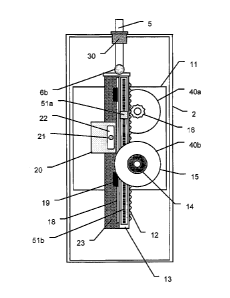
The PTO system 10 embodying the invention may employ a rack and
pinion drive train of the type shown in Figs. 3A, 3B and 3C to convert linear
reciprocating motion into electrical energy. The thrust rod 5 is driven back
and
forth (or up and down) by the float 1 to which it is connected via the bridge
arrangement 4. The thrust rod 5 is connected to rack apparatus which includes
a "toothed" rack assembly 12 overlying a rack support 13 to which is connected
a
brake rotor flange 23. The rack assembly moves in tandem with the movement
of the thrust rod. The rack assembly 12 passes back and forth through and
8
CA 02745387 2011-06-01
WO 2011/062576
PCT/US2009/006272
along a PTO mechanical housing 11 in which are located pinion gears 16, which
rotate as a function of the back and forth linear motion of the rack assembly
12.
Thus, linear force and motion is communicated to the PTO system 10 through
thrust rod 5 which is connected between the bridge 4 and the rack 12. The
linear force and motion of the rack 12 is then converted into rotational
torque and
motion by use of pinion gears 16 when they engage the teeth of the rack. The
mechanical/frame housing 11 of PTO 10 is fixedly connected to the spar 2 body
so as to transmit all mechanical reaction forces between the float 1 and the
spar
2 and to have relative linear motion between the PTO mechanical housing 11
and the rack 12. The PTO housing 11 may be constructed of metal (or any other
suitable Material) of sufficient thickness (e.g. 1 inch) to withstand the
loads and
reaction forces communicated between the float 1 and spar 2. The PTO frame
11 may be formed of steel panels that are machined after welding.
Alternatively,
the PTO frame may be a bolt-together structure which provides both weight and
cost improvements with no sacrifice in performance. The mass of the rack
assembly and of the PTO frame 11 and attached components are accounted for
in the float buoyancy calculation and in the spar buoyancy calculation.
The rack 12 may be formed of multiple rack segments. The length of the
rack and its width may have a wide range of values compatible with the
dimensions of the inner envelope of the spar. The number of teeth per unit
length
of the rack 12 is made compatible with the corresponding pinion gears 16 which
drive the generators. The rack segments may be mounted to, and on, a box like
rack support assembly 13 (see Figs. 3C and 5)- made of any suitable material
9
CA 02745387 2011-06-01
WO 2011/062576
PCT/US2009/006272
(e.g., aluminum) which provides the required stiffness while keeping the
weight
down. Linear bearings guide the rack 12 precisely past the pinion gears 16.
The
carriage bearings provide linear guidance to the rack assembly. These linear
bearings consist of specially-profiled steel rails 18 and a mating set of
linear
bearing carriage blocks 19 which ride on the rails. The bearing rails (see
Figs. 3A
and 3C) are mounted on the underside of the rack support assembly 13 and the
carriage blocks are fixed with respect to the PTO housing 11. A rack and
pinion
PTO, which includes a plurality of pinion gears, requires precision alignment
between the rack teeth and pinion gear teeth. A set of linear bearings and
rails
(18, 19) prevent off-axis forces being seen by the pinion gears 16 and
maintain
the required precision rack-gear interface, and ultimately assure reliable,
efficient
and long-life operation. As shown in the figures, in addition to fixing the
pinion
gears 16, the rack assembly 12 is guided by a pair of profiled rail linear
bearings
18, 19. The profile rails 18 are affixed directly to the rack assembly 12,
while the
bearing carriages, which ride on the profiled rails, are affixed to the PTO
housing
11. In this manner, inadvertent lateral forces applied to rack assembly are
reacted against allowing pure linear motion to be transmitted to the rack
assembly 12.
Means (not shown) may be provided for automatically lubricating the rack
and associated components.
Figs. 3A and 3B show two pinion gears (16a, 16b) used to drive two
corresponding generators (40a, 40b). The pinion gears are designed to have a
number of teeth (e.g. 20) compatible with the rack's teeth. The pinion gears
16
CA 02745387 2011-06-01
WO 2011/062576
PCT/US2009/006272
are fixedly connected to motor/generator shafts 15 which drive the rotors of
the
generators and whose rotary motion is supported by rotary bearings 14. Thus
the motor shafts 15 are integrated into a unitary pinion gear 16 (see Figs 3A,
3B,
3C and 5). The combination of integral pinion 16 and shaft 15 eliminates a
high-
torque coupling between the pinion gear and motor shaft.
Two generators (40a, 40b) are shown located within the PTO housing 11;
but, if space permits, more (or less) generators may be used and located
within
the PTO. The construction and operation of each motor/generator 40 for use in
practicing the invention is best explained with references to Figs. 5, 6A and
6B.
A generator 40 includes a stator portion 42, which may be fixedly connected to
the PTO frame, and a rotor portion 41 fixedly connected to the shaft 15 driven
by
pinion gear 16. The rotor portion includes a large number (e.g., 80, or more)
of
North-South magnetic pairs 44 disposed along the periphery of the rotor and
the
stator portion includes a similar large number of coils 45 also disposed along
the
periphery of the stator. The large number (e.g., 80) of poles (N-S magnet
pairs)
enables the frequency of the voltage signals generated by the generator to be
much higher than the frequency of the waves.
This stator/rotor generator design eliminates the need for gear boxes to be
connected to the pinion gears to increase the rotational speed and the
frequency
of the output signals. Gear boxes perform a useful function; but in WEC
systems
their use is problematic because of inertia, wear and tear, difficulty to
replace and
a decrease in the reliability and efficiency of the system.
=
11
CA 02745387 2011-06-01
WO 2011/062576
PCT/US2009/006272
For example, in one embodiment, the linear motion of the rack and pinion
mechanism causes a rotor (connected to the pinion gear) to rotate at
approximately 2.6 revolutions per second in response to a relative movement of
1 meter per second between float and spar, to produce an AC voltage having a
frequency of approximately 104 cycles per second.
The proposed generator used in this invention may be termed a "torque
motor". Although torque motors operate on the identical principle to that of a
conventional brushless dc permanent magnet motor/generator, the torque motor
typically has 5 to 10 times more magnetic pole pairs than a conventional
motor/generator. This means that for a given shaft speed the electrical
frequency
generated from a torque motor will be 5 to 10 times that of a conventional
motor.
The term "torque" motor arises from the fact that for a given power level, a
torque
motor will operate with approximately 5-10 times the torque of a conventional
motor.
Since the electrical frequencies for optimum mechanical to electrical
conversion are similar for torque motors and conventional motors, the optimal
rotational speed will be 5 to 10 times lower for a torque motor compared with
a
brushless motor. Since the input maximum linear motion speed is fixed within
the
range of 1 m/s and it is impractical to use a single stage pinion gear to
convert
the linear motion to optimum speed (-1500 RPM), a speed increasing gearbox
must be used in conjunction with a conventional motor. Thus, the torque motor
is
able to achieve the same optimal efficiency without the aid of a gear box.
12
CA 02745387 2011-06-01
WO 2011/062576
PCT/US2009/006272
Referring to the figures, note that the stator portion 42 has an outer shell
43 which is rigidly connected to the PTO housing 11. The shell 43 may form an
outer cooling jacket for the stator subassembly. The generator/motor stator
subassembly may contain water-cooling channels (not shown) on the outer
circumference. Small "wind scoops" on the rotor subassembly (also not shown)
provide cooling to the rotor through exchange of air within the generator.
As noted, the rotor portion 41 of each generator 40 is driven (rotated) by
movement of shaft 15 which is driven by a pinion gear 16 which is responsive
to
movement of rack 12. The shaft 15 also terminates in and is supported by a
rotary bearing 14 which allows smooth rotation of the generator rotor while
providing -a path for the linear reaction forces to be communicated to the
spar 2.
Fig. 6B, which corresponds to Fig. 6A, is a simplified schematic
representation of
the windings and magnets showing the numerous poles and coils used to
increase the effective frequency of the voltage signals generated by the
generator/motor 40.
A plurality of pinion gears (e.g., 16a, 16b) are positioned above the rack
12 and are made to turn (rotate) in response to the back and forth movement of
the rack. The linear mechanical motion of the rack is thus converted to rotary
motion of the pinion gears 16. The rotational speed of the pinion gears and
their
shaft is based on their gear ratio with the rack. Attached to each pinion gear
16
is the rotor portion 41 of a brushless DC torque motor/generator 40. A linear
force and motion is applied to the rack via the interaction of the float 1 and
the
13
CA 02745387 2011-06-01
WO 2011/062576
PCT/US2009/006272
spar 2 in a direction that is in opposition to that provided by the torque
motor/generator.
For example, as shown in Figs. 6A, in response to the float 1 moving
down, the thrust rod 5 moves (vertically) down and the rack 12 moves down
causing the pinion gear to rotate in the clockwise direction. The shaft of the
pinion gear is fixedly and rigidly connected to the rotor of the generator
causing
the magnets to rotate in the clockwise direction. As the magnets 44 rotate
they
generate a voltage in the stator coils 45 distributed along the stator portion
42,
which is rigidly connected to the spar 2 via the PTO housing 11. It is
significant
that in systems embodying the invention the rotor and stator may be formed, as
shown in Fig. 6A and 6B, to ensure that the frequency of the voltage signals
generated in the coils is above some value for nominal movement (speed) of the
rack
Likewise, in response to the float 1 moving up the thrust rod 5 moves
(vertically) up and the rack 12 also moves up causing the pinion gear to
rotate in
the counter clockwise direction. The shaft of the pinion gear is fixedly and
rigidly
connected to the rotor of the generator causing the magnets to rotate in the
counter clockwise direction. As the magnets 44 rotate they generate a voltage
in
the stator coils 45 distributed along the stator 42, which is rigidly
connected to the
spar 2 via the PTO housing 11. As already noted, it is significant that in
systems
embodying the invention the rotor and stator may be formed, as shown in Fig.
6A
and 6B, to ensure that the frequency of the voltage signals generated in the
coils
is above some value for nominal movement (speed) of the rack. The disclosed
14
CA 02745387 2011-06-01
WO 2011/062576
PCT/US2009/006272
apparatus has the advantage over previous embodiments in that the generator
element is a low speed brushless DC torque motor/generator. For WEC devices,
the linear velocity is typically in the range of 1 to 2 meters per second and
the
forces can be up to 500 kN. These high forces typically require a pinion gear
which has a large pitch diameter of approximately 150 mm. At this large pitch
diameter, the rotational speed of the motor is only 127 to 250 RPM. At these
low
rotational speeds, conventional high speed brushless DC motors are very
inefficient. Conventionally, a gear box with a gear ratio of approximately
10:1
would be used between the pinion gear and the generator to increase the
rotational speed seen by the generator. These gear boxes have two major
drawbacks, decreasing both the efficiency and the reliability of the WEC. By
eliminating this gearbox, the efficiency and reliability of the WEC PTO is
substantially increased.
Fig. 7 is a simplified block diagram showing that the output of each
generator coil is fed to a rectifier whose output is smoothed and collected in
a
capacitor bank to establish a DC voltage. The output from the capacitor bank
is
then coupled to an AC inverter to produce an AC voltage which may be coupled
via a cable to a power grid.
A linear position sensor 51 (see Figs. 3A) of predetermined resolution
(e.g., 0.1mm) may be mounted along the rack to provide track position to the
buoy's data acquisition and control system (not shown). The linear position
sensor 51 includes a first portion 51a which may be affixed to the rack
assembly
13 and a second portion 51b which may be affixed to the PTO frame 11. The
CA 02745387 2011-06-01
WO 2011/062576
PCT/US2009/006272
purpose of this sensor is to detect the relative motion between the float 1
and the
spar 2. This information may be used by the PTO control system (not shown) to
set the appropriate force for the PTO. This arrangement allows for optimal
impedance matching algorithms to be used and extract maximum energy from
the incident ocean waves.
The disclosed apparatus also has the ability to be used in conjunction with
selected adaptive impedance matching algorithms. Since the PTO directly
couples bi-directional linear force and motion to the generating elements,
without
the aid of mechanical clutches, accumulators or the like; it is possible for
the PTO
to operate in all four quadrants of the torque-speed plane. That is, the PTO
is
able to bOth act as a generator as well as motor in both directions. Although
the
PTO operates as generator for most of the time, it has been shown that brief
excursions into the motoring quadrants can improve the overall electrical
power
output from such a configuration.
In order to implement some form of impedance matching, the relative
position and velocity between the float and spar needs to be sensed and this
information needs to be provided to the WEC's on-board control computer (not
shown). A linear position sensor (such as sensor 51a, 51b shown in Fig. 3A)
can
be used. The linear position sensor may be a magnetostrictive type or any
other
suitable type including: photoelectric encoders, magnetic encoders and string
based potentiometers.
A mechanical seal 30 (see Figs. 2, 3A and 4, discussed below) is
disposed at the top of the around thrust rod (5) to prevent seawater from
entering
=
16
CA 02745387 2011-06-01
WO 2011/062576
PCT/US2009/006272
the spar enclosure and affecting the PTO. Fig. 4 shows a seal 30 which can
insulate the rack and pinion assembly from being affected by sea water while
allowing the thrust rod (5) to move back and forth (up and down and laterally,
at
an angle) with little friction. The seal is formed about the thrust rod and
the
opening for the thrust rod in the spar and includes a compliant rubber boot
(31)
extending upward from the spar and forming a collar (32) which functions as a
linear seal housing with a sealing material placed about the seal housing
between it and the thrust rod. The compliant boot (31) allows for significant
lateral motion (i.e. normal to the thrust axis) caused by misalignment and
tolerances of the float and spar external linear bearings in comparison with
the
orientation of the linear bearings which guide the motion of the rack
assembly.
This compliance of boot (31) and ball joint (6a) helps to prolong the life of
the
seal (30) by reducing lateral reaction forces being seen by the seal. The seal
(30)
contains sealing material (33) that is maintained at a pressure above the
pressure exerted by seawater; thus, preventing the ingress of seawater into
the
spar. A reservoir containing excess sealing material (34) and connected to the
seal package via a hose or pipe replenishes the sealing material as it is
consumed.
The relative motion between the float and spar can be controlled and
limited in order to prevent over-stroking of the power take-off, the impacting
of
mechanical end-stops and/or damage to the WEC equipment. A mechanism for
selectively locking the spar and float together includes a steel plate, or
flange, 23
denoted as a "brake rotor" (See Figs. 3A, 3C). The brake rotor 23 which may be
17
CA 02745387 2011-06-01
WO 2011/062576
PCT/US2009/006272
1 inch thick plate, is attached to the underside of the rack support assembly
13
(the side opposite to the side on which the rack 12 is attached) and extends
orthogonally. The brake rotor 23 can be clamped by a caliper brake assembly 20
so it can be used as a "linear" brake "rotor." A spring loaded, hydraulically
released caliper brake assembly 20 (see Figs. 3A, 3C) is affixed to the PTO
housing 11 so that the rack assembly 12 cannot move relative to the spar 2 in
the
event of high seas or periodic maintenance. The caliper 21 applies a braking
force through brake pads (22) which squeeze upon a linear brake fin or "rotor"
(23) which is fixedly attached to the rack assembly 12. The caliper brake
assembly is essentially a frictional brake. It should be appreciated that an
electromagnetic brake could be used in addition or instead.
As may be illustrated with reference to Figs. 3A and 3C, a caliper brake
may be selectively applied during severe storm conditions or during
maintenance
installation/retrieval of the buoy to limit motion between the float and spar.
The
caliper brake includes a caliper 21 and brake pads 22 which are activated to
press against and clamp a brake rotor 23 attached to the rack support 13 on
which is mounted rack 12. The caliper brake applies a clamping force and has a
relatively high coefficient of friction. In one embodiment, the caliper brake
is
normally locked. A hydraulic power unit provides pressure to unlock. The brake
locks under the following conditions: 1) high wave states, 2) low wave states,
3)
maintenance, 4) asynchronous loss of electrical power, and 5) accidental loss
of
hydraulic pressure. Alternatively, it could be normally unlocked and locked
under
specified conditions,
18
CA 02745387 2011-06-01
WO 2011/062576
PCT/US2009/006272
Under extremely severe conditions, the caliper brake might not have
sufficient holding power to prevent motion between the float and spar. To
limit the
relative motion between the float and spar when this condition occurs (i.e.,
when
the caliper brake allows slippage), the windings of the generator can be
shorted
by a commandable contactor, as shown in Fig. 8, to provide additional braking.
Normally, the relative displacement between the float and spar, and
therefore the stroke of the PTO device, can be controlled by controlling the
back-
torque provided by one or more generators. Generator torque can be controlled
by an "active rectifier" or "drive" that regulates the current from/to the
generator.
Under heavy sea conditions, the generator drive might not have sufficient
current
handling Capability to exert sufficient control of the generator current and
therefore its back-torque. In such a case, the current of, and back-torque
provided by, the generator(s) can be increased by shorting the generator
windings with components external to the generator. An external short provides
a
maximum amount of passive braking to the PTO. In some cases, it may be
desirable to limit the generator braking capability. In this case, the
generator
windings can be connected to low-impedance resistors (e.g., 47), as shown in
Figure 8. In Fig. 8 a selectively enabled contactor switch 46 is connected in
series with a resistor 47 across the generator 40 output. Decreasing the value
of
resistance of resistor 47 increases the current and the braking capacity of
the
operation.
As described above, the relative motion of the float and spar can be
constrained by regulating the current and back-torque of the generator
actively
19
CA 02745387 2011-06-01
WO 2011/062576
PCT/US2009/006272
using a "drive" or passively by externally shorting the generator windings.
Using
these means of motion limiting, the PTO components (e.g. pinion gears, rack)
must be sized to handle the resulting forces. Storm forces are often orders of
magnitude higher than the normal operational forces. In order to keep the size
and cost of the rack and pinion components to a reasonable level, it is
advantageous to size the rack and pinion components only for the maximum
operational forces (not the much higher forces seen during a storm). It may
therefore be necessary to have some other means to stop the relative motion
between the float and spar.
Thus, it has been shown that a WEC embodying the invention may include
at least one of the following features:
1- A PTO using a rack and pinion to drive a multi-pole torque
motor/generator;
2- A pinion gear integrally connected to a shaft connected to the rotor of
the generator;
3- A kinematic linkage system for transferring forces more efficiently;
4- A compliant floating linear seal;
5- A frictional brake;
6- An electro-magnetic brake; and
7- Positional sensor(s) for use in impedance matching and other tasks.