Note: Descriptions are shown in the official language in which they were submitted.
CA 02745561 2011-07-07
AUTOMATED SYSTEM AND METHOD OF PROCESSING BIOLOGICAL
SPECIMENS
BACKGROUND
Field
An automated system of processing biological specimens.
Background
In various settings, examination of biological specimens is required for
diagnostic
purposes. Generally speaking, pathologists and other diagnosticians collect
and study samples
from patients, and utilize microscopic examination, and other devices to
assess the samples at
cellular levels. Numerous steps typically are involved in pathology and other
diagnostic process,
including the collection of biological samples such as blood and tissue,
processing the samples,
preparation of microscope slides, staining, examination, re-testing or re-
staining, collecting
additional samples, re-examination of the samples, and ultimately the offering
of diagnostic
findings. Numerous medical or veterinary personnel may be involved in the
diagnostic processes,
including surgeons, phlebotomists or other operating personnel collecting
samples, pathologist,
histologists and other personnel processing, transporting and examining the
samples and so on.
The complexity of the tissue handling procedures from the operating room to
the laboratory and
back to the diagnosticians or surgeons have become increasingly complex in
large medical
environments where high volumes of samples need to be handled, processed and
examined on a
daily basis.
Various steps of the tissue handling procedures have been automated using
instruments each of which typically are controlled by a dedicated computer or
an on-board
computerized controller. In some laboratories, information can be shared
between automated
instruments and/or a networked laboratory or hospital information system, such
as to store
patient or tracking data. One example of an automated instrument is an
automated tissue
processing system in which biological samples are fixed and infiltrated with
paraffin in an
automated fashion. Exemplary tissue processing systems are the TISSUE-TEK VIP
and the
Docket No. 7705P030 2
CA 02745561 2011-07-07
TISSUE-TEK XPRESS processing systems available from Sakura Finetek U.S.A.,
Inc. of
Torrance, Calif.
Another example of automation is an automated microscope slide stainer and
coverslipper, which stains microscope slides and applies coverslips to the
slides in an automated
fashion. Examples of such automated staining and coverslipping systems are
TISSUE-TEK
PRISMA and TISSUE-TEK FILM combo system and TISSUE-TEK PRISMA and
TISSUE-TEK GlasTmg2 combo system available from Sakura Finetek U.S.A., Inc.
of Torrance,
Calif.
Despite the assistance of automated instruments, pathologists, other
diagnosticians
and laboratory personnel typically must be involved in numerous steps during
the processing and
examination of biological samples. For example, once a sample has been
stained, the stained
sample on a microscope slide may be physically examined under a microscope.
This typically
involves transport of the microscope slide to a diagnostician who is located
outside the
laboratory, or in other cases may involve a diagnostician going to the
laboratory to examine the
microscope slide. Alternatively, the stained sample on a microscope slide is
imaged with a
digital camera and the image of the sample is uploaded for examination by a
diagnostician.
Following this initial examination step, the diagnostician evaluates whether
additional
testing is required. Such additional testing might involve collecting further
samples from a
patient, or further testing of samples already collected. For example, the
diagnostician may
require that the existing sample be sectioned further and a different staining
regimen or other
protocol be applied. This can result in iterations of one or more of
collection, grossing,
processing, infiltration, embedding, sectioning, coverslipping, staining,
examination etc. In
addition, different coverslipped slides may require different drying times.
Accordingly, some
slides may be ready for examination while others are not. All of this can
result in time delays, as
well as tissue impairment. Following the iterations of additional tests and
procedures, the
pathologist repeats the examination process, and may then request still
further tests in an iterative
fashion until an ultimate finding is reached. Even with automated instruments
in these processes,
there are numerous transport, and human interventions required.
Docket No 7705P030 3
CA 02745561 2011-07-07
BRIEF DESCRIPTION OF THE DRAWINGS
The embodiments of the invention are illustrated by way of example and not by
way
of limitation in the figures of the accompanying drawings in which like
references indicate
similar elements. It should be noted that references to "an" or "one"
embodiment in this
disclosure are not necessarily to the same embodiment, and such references
mean at least one.
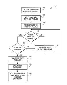
FIG. 1 is a flow chart of one embodiment of a method for automatically
processing
biological specimens.
FIG. 2 illustrates one embodiment of an automated system for processing
biological
specimens.
FIG. 3 illustrates one embodiment of an automated system for processing
biological
specimens.
FIG. 4 illustrates a top view of one embodiment of an automated system for
processing biological specimens.
FIG. 5 illustrates a side view of the automated system of FIG. 4 through line
5-5'.
FIG. 6 illustrates a side view of the automated system of FIG. 4 through line
6-6'.
FIG. 7 illustrates a top view of the automated system of FIG. 4 showing a
slide
placed in an imager.
FIG. 8 illustrates a side view of the automated system of FIG. 4 through line
8-8'.
FIG. 9 shows a perspective view of an embodiment of a storage module of the
automated system of FIG. 4.
Docket No. 7705P030 4
81714874
DETAILED DESCRIPTION
In the following paragraphs, the present invention will be described in detail
by
way of example with reference to the accompanying drawings. Throughout this
description,
the preferred embodiments and examples shown should be considered as
exemplars, rather
than as limitations on the present invention. As used herein, the "present
invention" refers to
any one of the embodiments of the invention described herein, and any
equivalents.
Furthermore, reference to various aspects of the invention throughout this
document does not
mean that all claimed embodiments or methods must include the referenced
aspects.
According to one aspect of the present disclosure, there is provided an
apparatus
comprising: at least one of a stainer module and a coverslipper module; an
imaging module; a
storage module; an automated transport module for transporting at least one
slide between at
least one of the stainer module and the coverslipper module, the imaging
module and the
storage module, the transport module is operable to transport the at least one
slide to the
storage module when it is determined that the imaging module is not available,
and from the
storage module to the imaging module when it is determined that the imaging
module is
available; a reader operable to read an identifier positioned on the at least
one slide; and a
controller for (1) directing transport of the at least one slide by the
transport module, wherein
the controller is in communication with the reader and reading of the
identifier indicates to the
controller that the at least one slide is on the automated transport module,
or (2) when the
slide is in the imaging module, reading of the identifier to associate a
digital image obtained
by the imaging module with the identifier positioned on the at least one slide
and (3) when an
image of the at least one slide has been obtained and the at least one slide
transferred to the
storage module, directing return transport of the at least one slide to the
imaging module for
additional imaging.
A further aspect provides a method comprising: processing at least one slide
having a biological specimen thereon; automatically determining whether an
imaging module
is available for imaging of the biological specimen on the at least one slide;
transporting the at
least one slide to the imaging module using an automated transport module when
it is
determined that the imaging module is available; transporting the at least one
slide to a storage
CA 2745561 2020-03-18
81714874
module using the automated transport module when it is determined that the
imaging module
is not available; communicating to a controller that the at least one slide is
being transported
by the automated transport module by reading an identifier positioned on the
at least one slide
using a reader, or when the slide is transported to the imaging module,
communicating to a
controller to associate a digital image obtained by the imaging module with
the identifier
positioned on the at least one slide; obtaining a digital image of the
biological specimen;
transporting the at least one slide to the storage module after obtaining the
digital image;
and after transporting the at least one slide to the storage module after
obtaining the digital
image, transporting the at least one slide to the imaging module from the
storage module.
There is also provided a system comprising: a processing module for processing
at
least one slide comprising a biological specimen thereon; an imaging module
for imaging the
biological specimen on the at least one slide; a storage module; a transport
module for
transporting the at least one slide between the processing module, the imaging
module and the
storage module; a reader operable to read an identifier positioned on the at
least one slide
being transported by the transport module; and a control module in
communication with the
transport module and at least one of the processing module, the imaging module
and the
storage module to control transport of the at least one slide, wherein the
control module
directs transport of the at least one slide to the storage module when the
imaging module is
not available or the at least one slide is not ready for imaging, and wherein
the control module
is in communication with the reader and reading of the identifier indicates to
the control
module that the at least one slide is on the automated transport module, or
when the slide is in
the imaging module, reading of the identifier allows the control module to
associate a digital
image obtained by the imaging module with the identifier positioned on the at
least one slide
and when an image of the at least one slide has been obtained and the at least
one slide
transferred to the storage module, the control module directs the return of
the at least one slide
to the imaging module.
In accordance with a still further aspect, there is provided a machine
readable
medium including program instructions that when executed by a controller
linked to at least
one processing module, an imaging module, and a storage module, cause the
controller to
perform a method comprising: processing at least one slide having a biological
specimen
5a
CA 2745561 2020-03-18
81714874
thereon at the one processing module; automatically determining whether an
imaging module
is available for imaging of the biological specimen on the at least one slide;
transporting the at
least one slide from the at least one processing module to the imaging module
or the storage
module; communicating to a controller that the at least one slide is being
transported by a
transport module by reading an identifier positioned on the at least one slide
using a reader or
when the slide is transported to the imaging module, communicating to the
controller to
associate a digital image obtained by the imaging module with the identifier
positioned on
the at least one slide, obtaining a digital image of the biological specimen;
transporting the
at least one slide to the storage module after obtaining the digital image;
and after
transporting the at least one slide to the storage module after obtaining the
digital image,
transporting the at least one slide to the imaging module from the storage
module.
According to another aspect, there is provided an apparatus comprising: an
imaging module; a storage module; an automated transport module for
transporting at least
one slide between the imaging module and the storage module, the transport
module is
operable to transport the at least one slide to the storage module when it is
determined that
the imaging module is not available, and from the storage module to the
imaging module
when it is determined that the imaging module is available; a reader operable
to read an
identifier positioned on the at least one slide being transported by the
automated transport
module; and a controller for (1) directing transport of the at least one slide
by the transport
module, and wherein the controller is in communication with the reader and
reading of the
identifier indicates to the controller that the at least one slide is on the
automated transport
module, or (2) when the slide is in the imaging module, reading of the
identifier to associate a
digital image obtained by the imaging module with the identifier positioned on
the at least
one slide and (3) when an image of the at least one slide has been obtained
and the at least
one slide transferred to the storage module, directing return transport of the
at least one slide
to the imaging module for additional imaging.
A further aspect provides an apparatus comprising: an imaging module; a
storage
module; an automated transport module for transporting at least one slide
between at least one
of the imaging module and the storage module, the at least one slide
comprising an identifier
that is operable to store information regarding a desired imaging protocol for
the at least one
5b
CA 2745561 2020-03-18
81714874
slide; and a controller for (1) directing transport of the at least one slide
by the transport
module, wherein the controller is operable to schedule an imaging of the at
least one slide, or
(2) once imaging has occurred, associating an image obtained by the imaging
module with the
at least one slide, based on information read from the identifier by a reader
that is in
communication with the controller and (3) when an image of the at least one
slide has been
obtained and the at least one slide transferred to the storage module,
directing return transport
of the at least one slide to the imaging module for additional imaging.
In overview, a system and process for performing a series of automated
operations
including tissue processing, imaging and tissue storage is disclosed. FIG. 1
shows a flow
chart of one embodiment of a process implemented by a system (i.e., machine-
readable
program instructions implemented in a processor connected to process control
modules). As
illustrated in block 102, process 100 includes obtaining at a material
handling system a
biological sample that has been mounted on a slide. The biological sample is
conveyed to a
material handling system, for example by manual transport, a cart or automated
transport. In a
hospital embodiment, the specimen may be delivered to a medical laboratory,
whether on-site
or at a remote location.
At the material handling system, the slide mounted specimen may be processed
via automated operations into a condition suitable for a desired examination.
In one
embodiment, processing includes staining the biological sample and applying a
cover slip to
the slide (block 104). Staining of the specimen may be optional. The slide
having the
specimen thereon is then transferred to a transport module (block 106). In
some
embodiments, the slide is transferred to the transport module using a robotic
transferring
device as will be discussed in more detail in reference to FIGS. 4-9.
Process 100 further includes determining whether the slide is ready for
imaging
(block 108). Such a determination may be based on, for example, the drying
time of the slide.
For example, different methods of coverslipping exist and each one requires
different drying
times. Representatively, a glass cover slip may require about a day to dry
while a film cover
slip may dry in about an hour. In this aspect, coverslipped slides that are
not ready (e.g. not
dry) for
5c
CA 2745561 2020-03-18
CA 02745561 2011-07-07
further processing (e.g., imaging) are transported to a storage module to give
them additional
time to dry (bock 112). Slides that are dry are determined to be ready for
imaging.
Process 100 further includes determining whether the imager is available for
imaging
(block 110). Imaging of a specimen on a slide typically takes longer than the
amount of time it
takes to stain, coverslip and dry the slide, because imaging must be done on
individual slides
(i.e., one at a time) while staining and coverslipping operations may be done
on a number of
slides at the same time (e.g., staining a batch of slides). For example, slide
imagers can perform
a 20x scan of a 15x15 mm tissue in about 2 1/2 to 3 minutes. Higher resolution
and z-stacking
requirements can double that time. This equates to an imager throughput of
from about 10-24
slides per hour. In contrast, up to about 500 slides per hour may be processed
through a
coverslipper and/or stainer. As a result, the imager is often times not ready
to image each of the
slides as they exit the coverslipper and/or stainer. If the imager is not
available, the slides are
transported from the coverslipper to a storage module for storing until an
imager is available
(block 112).
Once the imager is available, the slide is transported to the imager (block
114) for
imaging. At the imager, a digital image of the specimen is captured and stored
in a computer
memory. After a specimen, or group of specimens, is prepared for examination,
the specimen(s)
may be examined and the data may be made available to a diagnostician and/or
an optional
interpretation module which automatically interprets the data (block 116). It
should be noted that,
as used herein, "diagnostician" refers to any person who may wish to view
image data, such as
pathologists, surgeons, nurses, researchers, technicians and administrators.
Image data may be created, such as using a digital imager including, for
example, a
CCD technology. The image data preferably is made available for access by a
diagnostician if
desired, and optionally the diagnostician is notified such as by electronic
notification, such as by
an e-mail, computer screen pop-up announcement, banner announcement, pager
message or
automated phone call. In other embodiments, the image data may also be
accessed, or otherwise
made available, to an optional interpretation module. The interpretation
module may conduct
digital processing, such as by using pattern recognition technology in order
to develop a
preliminary diagnosis, and generate instructions or recommendations for
additional processing.
Docket No. 7705P030 6
CA 02745561 2011-07-07
The additional processing, illustrated with block 118, may include collecting
additional biological samples, or performing further processing on samples
already collected
such as running additional or different test procedures or staining protocols.
For example, after
imaging, a specimen may be transported by the transport module to the storage
module. The
specimen image may be examined, and if it is determined that further imaging
is necessary, the
specimen is retrieved from the storage module by the transport module and
transported to the
imager for imaging. Examination, imaging and interpretation of the sample may
be continued
until the system or diagnostician deems it to be complete. These repeated
tests and examinations
are referred to herein as iterative processing, testing or examination. In
another aspect of the
invention, the diagnostician may access reports that are based on the
comparison data created by
the interpretation module. In a further aspect of the invention, the
diagnostician may order or
conduct further iterative processing, testing or examination.
FIGS. 2-9 illustrate examples of automated systems for processing biological
specimens. In these figures, information pathways are illustrated with solid
lines and/or arrows
and material pathways are illustrated with double lines and outlined arrows.
As used herein,
"material" refers to any biological material including histological and
cytological specimens that
may be examined in a medical, autopsy, veterinary or research laboratory
procedure. The
biological material may include tissue samples or specimens, and/or biological
fluids such as
blood, plasma. etc. Although the illustrated examples are described in
relation to tissue, the
described systems and methods are not so limited. As used herein the
biological material will be
referred to interchangeably as a specimen, sample or material. In addition,
references relating to
processing of a "slide" herein refer to a slide having the biological material
thereon.
In the illustrated examples, the material pathways represent examples of
transport
paths that may be traveled by a physical sample in a laboratory or hospital. A
typical progression
of the material from one station or system component to the next is depicted
by the direction of
the arrow. However, it should be understood that the processing stations are
provided as
examples, as are the directions of material flow. It shall be appreciated that
more, fewer or other
processing stations may be used in practice of the present invention, and/or
more, fewer or other
Docket No. 7705P030 7
CA 02745561 2011-07-07
material paths and directions may be used in the practice of the present
invention. In addition,
the stations may be in any order and any orientation (e.g. vertically stacked
or side by side).
Any form of transport may be used that is sufficient to automatically
transport the
material as indicated by the material pathways. For example, material may be
transported by a
robotic device from one station to the next as will be discussed in more
detail in reference to
FIGS. 4-7. The term robot or robotic is to be interpreted broadly as a
conveyance, transfer
device, electro-mechanical transfer device or mechanism, or automatically
controlled,
reprogrammable, multipurpose manipulator programmable in three, four, or more
axes. The
robotic device may take various forms or configurations, consistent with its
intended purpose.
The robotic device may be programmed with an application program, program
routine, or other
set of instructions. The program or set of instructions may specify one or
more operations the
robotic device is to autonomously or at least semi-autonomously perform.
Representatively, the
program or set of instructions may specify the movements (e.g., coordinates,
distances,
directions, etc.), timing or triggers, and like information associated with
the operations. In some
embodiments, the material may also, or alternatively, be hand carried from one
station to the
next. Additionally, one machine may perform multiple steps with no physical
movement of the
material from one station to another being required.
In the embodiment of FIG. 2, a specimen mounted on a microscope slide is
transported to staining module 210. Prior to transporting the specimen to
staining module 210,
the specimen may be processed through, for example, a grossing station (in the
case of non-fluid
specimens), a tissue processor where the specimen is treated with a series of
reagents, an
embedding station where it may be infiltrated with paraffm and embedded and a
microtome
station where the specimen is sectioned. Specimen sections created in the
microtome station are
positioned on the microscope slide. Slides requiring deparaffinization may be
placed in an oven
prior to staining, or placed directly in the stainer if the stainer is
equipped with a built-in oven or
can perform a chemical deparrafinization step.
Any staining or other test protocol may be performed by the staining module
210 as
desired. In one embodiment, an automated stainer is used. In an example,
staining with
hematoxylin and eosin ("H & E") is performed in staining module 210. Other
staining methods
Docket No. 7705P030 8
CA 02745561 2011-07-07
such as special stains (SS), immunohistochemistry (IHC), and in situ
hybridization (ISH) can
also be performed.
In one embodiment, following staining, the samples may be transported along
material path 217 to coverslipper module 220 to be coverslipped.
After staining and/or coverslipping, the slide may proceed to imager 230 or
storage
module 202. In some embodiments, where it is desirable for imaging of the
slide to be delayed,
the slide is transported to storage module 202 for storage until imaging is
desired.
Representatively, different methods of coverslipping exist and each one
requires different drying
times. Coverslipped slides that are not ready (e.g. not dry) for further
processing are transported
to storage module 202 along material path 203. Once the slides are ready, they
may then be
transported along material path 205 to imager 235. In this aspect, the
differences in drying times
from slide to slide are automatically resolved by the automated system.
In some embodiments, the laboratory can select delay criteria based on the
coverslipping technique used and the type of sample (histology v. cytology,
monolayer slides v.
smears, etc.). For example, the laboratory may determine, based on the
coverslipping technique
to be used and the type of sample on the slide, that the slide should be
stored for a period of time
prior to imaging. This information may be contained in an identifier
associated with the slide.
Examples of identifiers include a radio frequency identification (RFID) tag,
barcode that may be
read by a reader associated with the system that provides information to the
automated system.
The automated system may read the identifier and follow the assigned
processing protocol. In
this aspect, after coverslipping, the slide is transported to storage module
202 and stored for the
predetermined period of time. After such time, the system may alert the
transport module to
retrieve the slide from storage module 202 and transport the slide to imager
230 for imaging.
In addition to drying times, the availability of imager 230 may further delay
imaging.
In particular, imaging of a specimen on a slide typically takes longer than
the amount of time it
takes to stain, coverslip and dry the slide. For example, current commercially
available slide
imagers can perform a 20x magnification scan of a 15x15 mm tissue in about 2
1/2 to 3 minutes.
Higher resolution and z-stacking requirements can double that time. This
equates to an imager
Docket No. 7705 P030 9
CA 02745561 2011-07-07
throughput of from about 10-24 slides per hour. In contrast, up to about 500
slides per hour may
be processed through the stainer/coverslipper modules. As a result, the imager
is often times not
ready to image each of the slides as they exit the stainer/coverslipper
modules. The identifier
associated with the slide may store information regarding the desired imaging
protocol for the
slide (e.g., a 10x scan, a 20x scan or a 40x scan). Upon reading the
identifier, the system
schedules imaging of the slide with an imager capable of imaging at the
desired magnification. If
the desired imager is not available when the slide is otherwise ready for
imaging, the slide is
transported from staining module 210 and/or coverslipper module 227 along
material path 203 to
storage module 202 for storing until imager 230 is available.
It is further contemplated that after a specimen is imaged by imager 230, the
specimen
slide may be transported along material path 205 to storage module 202. The
slide may be stored
in storage module 202 for future testing and/or examination.
Once the specimen is ready for imaging, at least one image of the material
specimen
is obtained by imager 230. The imaging protocol for each slide which is to be
followed by imager
230 may be flexible and can be defined at any time by, for example, the
diagnostician (e.g.,
pathologist). In this aspect, the diagnostician can have real time control of
the imaging process
remotely. For example, a pathologist may examine an image and determine that
additional
images of the slide are necessary. Representatively, the pathologist may
determine that images at
a different magnification are necessary or that the imager should focus deeper
into a tissue area.
According to the automated system disclosed herein, the pathologist may
instruct the system to
obtain further images. The system will then automatically retrieve the
specimen from storage
module 202 and transport it to imager 230 for further imaging as requested.
The pathologist may
receive the results the same day as the request, as opposed to current imaging
systems which
often process highest resolution and z-stacking images overnight.
Imager 230 may include one or more imagers. The imager can be any system that
generates images that can be interpreted manually interpreted or, optionally,
automatically
interpreted by interpretation module 290. In the illustrated embodiment,
imager 230 includes a
microscope and a camera capable of recording digital images of the
microscope's view field. For
example an optical CCD based camera can be used to generate the digital image
data. The digital
Docket No. 7705P030 10
CA 02745561 2011-07-07
image data can be stored in any fashion that provides for access to the data
as required by
interpretation module 290, diagnostician work station 240 and/or technician
work station 250
and/or as desired by anyone needing access to the image data, such as
diagnosticians or
laboratory personnel. Examples of suitable data storage are local storage
devices associated with
imager 230 (such as hard drive, removable memory, flash memory, optical memory
such as CD
or DVD etc.), and/or networked memory such as diagrammatically illustrated by
data storage
260. It should be noted that any form of information may be generated by
imager 230, in addition
to the image data. For example, imager 230 may optionally associate other
types of data, such as
a log of patient information associated with the image data and as discussed
further herein.
Alternatively, another processing system may associate the image data with
other data.
In one embodiment, the type of information generated is intended to be
sufficient for
interpretation module 290 to perform its interpretation processing and
generate the desired report.
Interpretation module 290 may take any desired form, such as for example, a
dedicated
computing system, or alternatively it may be a module running on a computing
system used for
multiple purposes. In additional examples, it may be freestanding, a part of
imager 230, part of
hospital information system 270, part of laboratory information system 280, or
it may be in any
location where data may be received from imager 230. Although the figure
depicts a single
interpretation module 290, it should be understood that plural interpretation
modules 290 also
may be used. In further examples, diagnostician work stations 245 may include
interpretation
modules 290 or interpretation module clients that enable the diagnostician to
locally conduct an
interpretation based on the data available including, without limitation,
image data from imager
230.
In the embodiment of FIG. 2, interpretation module(s) 290 is in communication
via
communications infrastructure 200. Interpretation module 290 may access data
as desired,
whether directly from imager 230, via data storage facility 260, or via local
data storage.
Interpretation module uses the image data and other data to perform an
analysis and a
recommendation. In an embodiment, the analysis includes a pattern recognition
analysis in a
pattern recognition system of interpretation module 290. In one form of
pattern recognition,
image data from imager 230 is compared to a database of known patterns. If a
sufficient level of
Docket No. 7705P030 11
CA 02745561 2011-07-07
correspondence is found, a matching pattern is located upon which a
recommendation, diagnosis
or further processing instruction can be made. The pattern database can be a
part of interpretation
module 290, or located externally, such as for example in data storage 260 or
laboratory
information system 280.
Following imaging by imager 230, interpretation module 290 may be configured
to
determine if the imaged sample should go to storage module, in which case it
proceeds along
material pathway 227, or interpretation module 290 may be configured to
determine whether the
particular sample needs to undergo additional processing, such as that it
should go to a
diagnostician or other personnel for personal inspection, in which case it
proceeds along material
pathway 237.
Alternatively, interpretation module 290 may be configured to determine if
further
processing of the tissue represented by the imaged sample is required. In such
case, a new
sample of the tissue is necessary for interpretation. In one embodiment,
additional section(s)
(samples) of the same tissue may have been placed on slide(s) and those
slide(s) sent to storage
module 202 with a label that links the slide(s) to the imaged sample. In this
embodiment, the
slide(s) are not stained or coverslipped, and are kept aside. These slides
could be identified as
being extra sections that should not be stained and kept in the storage area
until called back for
staining and coverslipping. For example, these extra slide(s) may have the
same identification
information as the original or primary, perhaps with an additional indicator
(e.g., an additional
letter or number) to indicate the slide(s) are extra slide(s). If they are not
needed, these slides can
be discarded after, for example, a user-defined period of time has elapsed or
the case has been
completed and signed off. Extra sections are cut and extra slides prepared and
stained only when
there is a requirement for more staining protocols. In an automated handling
system that also
includes handling of tissue blocks, the request for more staining would be
transferred to
microtomy module 205. In one embodiment, a tissue block, including a formalin-
fixed tissue
section in a paraffin block from which another tissue section may have been
taken and placed on
a slide, includes an identification tag such as a bar code or RFID tag. In
response to a signal
from a controller, the tissue block is retrieved and transported automatically
from a storage
module (e.g., storage module 202) to microtomy module 205. The tissue block is
stored and may
Docket No. 7705P030 12
CA 02745561 2011-07-07
be retrieved by the identification tag. The tissue block would be forwarded to
the microtomy
area for more sections to be taken.
Representatively, once a new sample is placed on a slide, the new sample
proceeds to
stainer module 210 where it may undergo operations such as special staining,
immunohistochemistry (''IHC"), in situ hybridization ("ISH"), multiplexing or
other staining or
testing procedures. Subsequently, the new sample may proceed along the
material path, for
example, back to imager 230. Ultimately it is desired that a tested and imaged
sample be stored
as indicated by storage module 202. In this example, after inspection by a
diagnostician or other
person, the original sample may be designated for storage, such as in storage
module 202 and the
new sample from the same tissue section designated and further processed. The
new sample may
be processed and inspected and sent to storage The original sample and the new
sample are
linked by an identification tag. Later, either or both the original and the
new sample can
optionally be retrieved from the storage module 202, if desired.
Thc work stations, such as diagnostician work stations 240 or other work
stations,
such as technician work stations 250 can have any desired structure, including
computing
systems serving as controllers in communication via communications
infrastructure 200 with
other processing stations or components of the system. The work stations may
optionally also
include other components that might be useful in a work area, such as material
storage units,
furniture, phones etc. In an embodiment, the work stations 240, 250 provide
access to
information concerning the processing of biological samples, and the results
of the processing,
including image data from the imager 230 and interpretation data or reports
from the
interpretation module 290. Technician work station 250 may be in communication
with data
storage 260 via path 257. In another embodiment, a system may not include work
stations such
as diagnostician work stations 240 and/or technician work stations 250.
As the material proceeds along the material pathways and through the
processing
systems, information may be shared between the numerous devices using various
information
pathways that form communications infrastructure 200. It should be noted that
communications
infrastructure 200 may be any form of communication system enabling
communications between
and amongst individuals, computer systems and/or automated processing systems.
Docket No. 7705P030 13
CA 02745561 2011-07-07
Representatively, the communications infrastructure may be a computer network
that is wired,
wireless or a combination of wired and wireless. For example, information
access points may be
wired into the network and/or joined to the network via a wireless portal.
Although the illustrated
example shows a networked system in which communications are performed via a
network,
direct communications also may be conducted. For example in one embodiment,
staining module
210 may have a direct communications link with coverslipper module 220 and may
access the
communications network via a node in coverslipper module 220, or alternatively
it may have a
direct network link. It should be understood that any suitable communications
pathway structure
is envisioned which would enable suitable sharing of information between and
amongst various
stations. Likewise, it should be understood that, in other embodiments, not
all of the stations may
have a direct communications path. Furthermore, it should be understood that
the communication
pathways can take any form, such as digital, analog, wired, wireless, paper,
oral, telephonic, etc.
In one embodiment, a laboratory network may be provided as the portion of the
communications infrastructure 200 between and amongst the laboratory
instruments, depicted
with reference numbers 210, 220, 230, 202 and also laboratory information
system 280 and other
work stations 240 and 250 (which might include a computer system such as for
example one or
more personal computers and/or computer servers). The laboratory network may
be networked
with a hospital network that is also a part of communications infrastructure
200. In such an
embodiment, other devices may have access to the information available on
laboratory
information system 280 or other laboratory devices via the communications
infrastructure 200.
Such other devices include for example, diagnostician or administrator work
stations 240,
hospital information system 270, and in some embodiments interpretation module
290 as well. It
should be understood that the flexibility of the information pathways is
directed to enable the
necessary information flow to track biological samples being processed however
desired, and to
distribute the necessary information to the appropriate users. Numerous
alternative
communications system structures may be selected to meet this need, and the
illustrated and
discussed examples are provided for illustrative purposes only, not to limit
the scope or
flexibility of the system.
Docket No. 7705P030 14
CA 02745561 2011-07-07
Referring to the illustrated example, communications pathways 203, 205, 207,
215,
225, 235, 245, 255, 265, 275, 285, 295, represent examples of communications
pathways
between staining module 210, coverslipper module 220, imager 230, storage
module 202,
diagnostician work station 240, technician work station 250, local or remote
data storage 260
and/or hospital information system 270, laboratory information system 280,
interpretation
module 290, or any other desired station or component of the system.
The sharing of information may be automated, manual or conceptual. For
example,
information may be shared directly by two machines in communication with each
other, it may
be made available to a user who can manually input it into another device, or
a single machine
comprising more than one device shown in FIG. 2 can engage in internal
communication. This
sharing of information often involves two-way communication. For example,
images from a
patient having a chronic condition may be sent to a database of patient
information storage, and
previously obtained information regarding the same patient may be retrieved
from the database in
order to monitor the progression of the condition. In another embodiment, each
station in the
material path is capable of communicating via the communications
infrastructure 200 and the
stations may communicate the progression of the material along the material
pathways as well as
other information, as discussed in further detail below.
In another embodiment, biological specimens, slides, trays, containers,
workpieces,
and locations throughout the system may be identified with machine
understandable codes, such
as provided by RFID tags, shape identifiers, color identifiers, numbers or
words, other optical
codes, barcodes etc. The identifiers can be recorded to generate data provided
to a database, such
as data maintained in data storage device 260, by a processor (any computing
devices), hospital
information system 270, laboratory information system 280 or any combination
thereof.
Examples of data that may be tracked include patient information and history,
information
regarding biological sample(s) collected, arrival and departure times of
biological samples, tests
performed on the samples, processes performed on the samples, reagents applied
to the samples,
diagnoses made, associated images and so on.
FIG. 3 illustrates an embodiment of a system for automatically processing a
biological specimen. System 300 includes transport module 302. Transport
module 302 may
Docket No. 7705P030 15
CA 02745561 2011-07-07
automate, or at least partially automate, the transfer of slides or other
tissue holders between the
stations, namely between one or more of staining module 304, coverslipper
module 306, imagers
308, 310, 312, storage module 314 and microtomy module 307. Automatically
transporting slides
or other tissue holders between staining module 304, coverslipper module 306,
imagers 308, 310,
312 storage module 314, and microtomy module 307 as opposed to manually
transferring the
slides or other tissue holders, offers certain potential advantages. For one
thing, it may free
personnel from the necessity of having to performing these sometimes
repetitive or tedious
operations manually. Advantageously, this may allow the personnel to perform
more value-
added operations and/or other operations less amenable to automation. For
another thing, the
transport module may be better suited for performing these operations
faithfully and timely than
the personnel, who may at times be distracted with other tasks, or forget or
be unable to perform
these operations faithfully or timely. In particular, manual transport by
personnel may result in
missed slides, slide breakage during handling, misplacement or misreading of
slides by the
imager. In addition, in the case of slide storage, transport by personnel to
the storage module can
result in misplaced slides, incorrect documentation of slides stored within
the storage module
and/or costly and lengthy slide retrieval from the storage module.
Advantageously, automated
transport of the slides may allow improved productivity or throughput by
reducing instrument
downtime waiting for samples to be transferred manually. Similar advantages
can be offered by
automating the transfer of tissue blocks between microtomy module 307 and
storage module 314.
In one embodiment, transport module 302 may be a robotic device capable of
transporting a slide between stations. In one embodiment, transport module 302
may be an X-Y-
Z robotic device dimensioned to transport one or more slides between stations.
Representatively,
transport module 302 may be a track and elevator system. The track system may
be a conveyor
belt or plate system that transports the slide horizontally in an "x-"
direction. In this aspect, one
or more slides may be placed on the conveyor and conveyed between the desired
stations, for
example, between coverslipper module 306, imager 308 and storage module 314.
In one
embodiment, the conveyor belt system may have two separate conveyor belts such
that one
conveyor belt transfers the slide in one direction and the other conveyor belt
transfers the slide in
the opposite direction as illustrated by arrow 316. Alternatively, as
described with reference to
FIGS. 4-9, a single conveyor belt system may be used to transport the slide in
more than one
Docket No. 7705P030 16
CA 02745561 2011-07-07
direction. Transport module 302 may further include an elevator device. The
elevator device
transports the slide vertically in a y-direction when it is desired that a
slide be positioned at a
location above or below the conveyor belt. The elevator device may further
include a component
for transporting the slide in and out of the elevator in the z-direction.
Staining module 304 and coverslipper module 306 may be an integrated slide
stainer
and coverslipping system. Alternatively, staining module 304 and coverslipper
module 306 may
be in separate instruments at different locations. In the case of an
integrated system, staining
module 304 and coverslipper module 306 may be a staining/coverslipping system
such as the
TISSUE-TEK PRISMA and TISSUE-TEK GLASTmg2 combo system or TISSUE-TEK
PRISMA and TISSUE-TEK FILM combo system commercially available from Sakura
Finetek U.S.A., Inc., Torrance, CA. In one embodiment, staining module 304 may
have
hematoxylin and eosin stain (H&E) and special staining (SS) capabilities. At
H&E/SS staining
and coverslipping, the biological sample may undergo H&E or SS staining and
optional
coverslipping. Other staining or testing protocols also can be performed.
During operation, an individual slide or group of slides placed in a basket
may be
loaded into staining module 304 and stained according to a desired staining
protocol. In the case
of a group of slides, the staining protocol can be the same for all slides or
selected from a
staining protocol menu, either by an operator or automatically by reading a
bar code, an RFID or
any other protocol identification device. Once the staining protocol is
complete, the slide or
group of slides within the basket is automatically transferred to coverslipper
module 306 for
individual cover slipping. The identifier associated with each slide is then
read as the slides are
coverslipped and either placed as a group in a basket or individually fed onto
transport module
302.
In an alternative embodiment, where a group of slides are stained together,
the slides
may be singulated (separated from the group) in staining module 304 and placed
on transport
module 316. For example, where a group of slides are stained together in a
basket, a pick and
place robotic device in staining module 304 may transfer the slides
individually to transport
module 316. From transport module 316, the slides may be conveyed to
coverslipper module
306, or, without a coverslip, to one of imagers 308, 310, 312 or to storage
module 314.
Docket No. 7705P030 17
CA 02745561 2011-07-07
Imaging methods (quick-scan, 20x, 40x, z-stack, etc.) at imagers 308, 310, 312
can be
pre-assigned to each slide according to a laboratory default or specific
instructions from, for
example, a pathologist. In the case of basket-grouped slides, in one
embodiment, each of the
slides would be assigned the same scanning method(s). Individual slides or the
basket of slides
may be assigned to one of imagers 308, 310, 312 based on the imagers
availability or according
to laboratory defined rules, such as dedicating one or more imagers to a
specific scanning method
(e.g., quick-scan, 20x, 40x or z-stack) or a plurality of methods.
In one embodiment, a slide including a biological sample is individually
transported
by transport module 302 to one of imagers 308, 310, 312 and/or storage module
314. If the slide
is ready for imaging (e.g., dry), the system checks to see if, for example,
imager 308 is available.
Imager 308 is determined to be available if, for example, it is properly
functioning and not
currently imaging another sample on a slide. If imager 308 is not available,
the availability of
imager 310 is determined. If imager 310 is not available, the availability of
imager 312 is
determined. This process continues, until an available imager is found.
Alternatively, an
imaging schedule between the slide and a particular imager may be
predetermined.
Representatively, information relating to a period of time sufficient to allow
the slide to dry may
be assigned to the slide and imagers 308, 310 and 312 may be on an imaging
schedule. The
system may determine which imager will be available after the drying period
expires. Once an
available imager is determined, the slide is transported by transport module
302 to the available
imager. Although three imagers are illustrated in FIG. 3, it is contemplated
that fewer than three
or more than three imagers may be included in system 300.
If none of imagers 308, 310, 312 are available or there are other conditions
which
require delay in imaging (e.g., waiting for slide processing instructions),
transport module 302
transports the slide to storage module 314. The slide remains in storage
module 314 until one of
imagers 308, 310, 312 become available and/or processing instructions are
received. Once an
imager is determined to be available, the slide is transferred from storage
module 314 to transport
module 302 using, for example a robotic device, and transported by transport
module 302 to the
available imager for imaging. Upon completion of imaging, the slide may be
transported by
transport module 302 from imager 308, 310 or 312 to storage module 314. The
image may be
Docket No. 7705P030 18
CA 02745561 2011-07-07
communicated to a diagnostician, for example a pathologist, for immediate
examination. Via a
computer (e.g., a personal computer), the pathologist can then examine an
image of a sample on
a slide for viewing and recall a slide for more imaging work if desired.
Alternatively, if it is
determined that no further examination of the slide is desired, the slide may
be removed from the
storage module 314.
In one embodiment, storage module 314 may include more than one storage
module.
In this aspect, one or more of the storage modules may act as short-term
storage areas for slides
likely to need more imaging work. In addition, one or more of the storage
modules may act as
long-term storage areas for slides which are unlikely to require more imaging
work in the near
future. The long-term storage modules may be located within the laboratory or
remotely.
In one embodiment, storage module 314 is configured to group slides (and
tissue
blocks for the block storage system) according to user-defined criteria. For
example, slides
pertaining to a patient case could be placed in the same area. Then cases or
blocks can be located
by date of production, by physician, by provenance, or by a combination of
these criteria.
Representatively, as noted above, a slide may contain an identifier that may
be read by a reader
(e.g., RFID reader, bar code reader). That identifier (e.g., RFID, bar code)
may contain
information (e.g., letters, numbers and/or symbols) indicating a date of
production, a physician
and/or a provenance. When the information is read by a reader, the information
may be sent to
the controller 400 or to other devices through the communications
infrastructure.
Automated system 300 as illustrated in FIG. 3 provides fully automated
movement of
slides between staining module 304, coverslipper module 306, imagers 308, 310,
312 and storage
module 314. In this aspect, system 300 provides a seamless and continuous
workflow which is
in sync with other laboratory processes and eliminates the need for overnight
processing and
batching while reducing personnel errors and liabilities. It is further noted
that there are no touch
points from staining to storage in system 300 therefore system 300 is believed
to satisfy even the
most stringent quality control programs such as Lean and Six Sigma.
FIG. 4 illustrates an embodiment of the system of FIG. 3. In this embodiment,
stainer module 304 is a TISSUE-TEK PRISMAOstainer and coverslipper module 306
is a
Docket No. 7705P030 19
CA 02745561 2011-07-07
TISSUE-TEKO FILM coverslipper, both commercially available from Sakura
Finetek USA.
The TISSUE-TEK PRISMAO stainer module and TISSUE-TEK FILM coverslipper
module may be connected to one another and a loading container used in the
coverslipper module
to hold one or more racks of slides prior to a coverslipping operation may
move between the
coverslipper module 306 and stainer module 304. A brief description of the
interaction between
these modules is presented in the following paragraphs.
In order to automate the movement of the loading container in the coverslipper
module 306 between coverslipper module 306 and stainer module 304, software
instructions and
a data link between coverslipper module 306 and stainer module 304 are
provided. Such
instructions and link may be solely between coverslipper module 306 and
stainer module 304.
Alternatively, a control system may be connected to each of strainer module
304, coverslipper
module 306, imagers 308, 310, 312, storage module 314 and transport module 302
that may be
used to transport a slide between imagers and the modules. FIGS. 4-9 describe
controller 400
connected to each of the noted modules and imagers. In such case, instructions
regarding the
transfer and a data link may be established between the modules and imagers
and the control
system. In such case, controller 400 may control the transfer operations
between stainer module
304 and coverslipper module 306. Controller 400 may also control (e.g., direct
operation of) the
various other modules and imagers as well as control slides relative to the
modules and imagers.
Referring again to movement of a loading container from stainer module 304 to
coverslipper module 306 , the loading container sits on a plate that is
connected to wires that
move the plate and the loading container in an x- and y-direction,
respectively, by two-step
motors. The plate may move the loading container in an x-direction into the
stainer.
In operation, a transfer arm of stainer module 304 retrieves a rack of slides
and moves
the rack along an xy axis to one or more individual staining stations. The
transfer arm transfers a
rack of slides to an appropriate staining station and then lowers the rack
into that staining station
for staining (a z-direction). Following staining, the transfer arm removes the
rack of slides from
the staining station and moves in x- and y-direction to another staining
station or, when all
staining operations are complete, to a transfer station where the rack of
slides is to be transferred
from the stainer to the Film coverslipper module (coverslipper module 306).
Docket No. 7705P030 20
CA 02745561 2011-07-07
For a transfer operation between stainer module 304 and coverslipper module
306, the
loading container in coverslipper module 306 receives instructions to move
from coverslipper
module 306 to stainer module 304 through the adjacent doorways in each device.
The loading
container is moved by the plate on which it sits along a single plane (xy
plane) from the
coverslipper to a position inside the stainer adjacent the doorway of the
stainer module. Once
inside the stainer module, the transfer arm lowers the rack of slides into the
loading container.
The loading container typically contains a solution such as xylene that wets
the slides. The
loading container then moves on the x-direction plate from the stainer into
the coverslipper again
through the adjacent doorways. A cover slipping operation including placing a
film-type cover
slip on individual slides in the basket of slides is then performed in the
coverslipper.
Transport module 302 may be a robotic device capable of transporting a slide
between
stations. In the embodiment shown in FIG. 4, transport module 302 may be a
robotic device
including conveyor 402 that is a conveying system to transport a slide or
group of slides
horizontally in a loop between stainer module 304/coverslipper module 306,
imagers 308, 310,
312 and storage module 314. In this embodiment, conveyor 402 transports a
slide in one
direction as illustrated by arrow 403 from stainer module 304 or coverslipper
module 306 to
imagers 308, 310, 312 and to storage module 314 and in an opposite direction
as illustrated by
arrow 405 from storage module 314 to imagers 308, 310 and 312. In one
embodiment, conveyor
402 may be a conveyor belt or a set of conveying pallets disposed in a
horizontal plane and
dimensioned to transport a slide or group of slides. A conveying system that
is a set of
conveying pallets may be similar to systems currently used in luggage
carousels at commercial
airports. Such carousels typically include a deck that is surrounded by
support wheel tracks. The
support wheel tracks define a path that is frequently oval shaped. Evenly
spaced along the wheel
tracks are pallet support members. Attached to each end of the pallet support
members are
support wheels. The support members are configured to be transported along the
support wheel
tracks by the rolling of the support wheels. The support members are connected
to each other at
the top by straps that run between support members. The bottoms are connected
to each other by
rigid links. Thus, the support members, the support wheels, and the straps
function in a manner
analogous to a train on endless railroad tracks.
Docket No. 7705P030 21
CA 02745561 2011-07-07
Attached to the pallet support members are pallets. The pallets are designed
to
overlap one another and are secured to the pallet support members to form a
flexible surface.
The overlap configuration of the pallets allows them to slide relative to each
other as the pallets
travel around the corners of the tracks. The leading edge of the pallets are
secured to the support
members by fasteners. Each of the pallets may have a slight bend to negotiate
the curves in the
unit.
In the embodiment shown in FIG. 4, conveyor 402 receives a slide from
coverslipper
module 306 and conveys the slide to one of imagers 308, 310, 312. Referring to
the TISSUE-
TEK FILM coverslipper, coverslipper module 306 individually places a film
strip on a slide.
With the system described in reference to FIG. 4, the slide is then moved to a
discharge position
in coverslipper module 306 and discharged onto conveyor 402 from coverslipper
module 306
onto conveyor 402. A discharge position in coverslipper module may be
established at a position
downstream of the coverslipping operation. Referring to FIG. 4, a slide, such
as slide 424, is
discharged onto conveyor 402 in a manner that its length dimension is disposed
across a width
dimension of conveyor 402. Reader 423, such as an RFID or bar code reader, may
be positioned
at a discharge point onto conveyor 402 or downstream from a discharge point to
read an
identifier on slide 424. Reader 423 is connected to controller 400 to indicate
to controller 400
that slide 424 is on conveyor 402. Once delivered to conveyor 402, conveyor
402 conveys slide
424 toward imagers 308, 310, 312.
As noted earlier, in this embodiment, multiple slides are brought to
converslipper
module 306 from stainer module 304 in a rack. In coverslipper module 306, the
slides are
singulated (separated from other slides in a rack) for coverslipping. In one
embodiment, all
stained slides in coverslipper module 306 are coverslipped. In another
embodiment, a
coverslipping operation may be bypassed. Such bypass can occur at the
singulation point in
coverslipper module 306. According to this embodiment, a slide is singulated
and either directed
to be directly discharged onto conveyor 402 or to be coverslipped and then
discharged.
In one embodiment, a slide retaining device is positioned adjacent to or
connected to
conveyor 402. Slide retaining device 420, in one embodiment, is an oval-shaped
chain or belt
Docket No. 7705P030 22
CA 02745561 2011-07-07
(e.g., a continuous loop) having projections 422 extending outwardly
therefrom. Projections 422
are spaced from one another at approximately a width of a slide.
As shown in FIG. 4, stainer module 304, coverslipper module 306 and imagers
308,
310, 312 are positioned on one side of conveyor 402. Slide retaining device
420 is positioned on
a side of conveyor 402 opposite to the side including stainer module 304,
coverslipper module
306 and imagers 308, 310, 312. Projections 422 of slide retaining device 420
project outward in
a direction toward conveyor 402. A length of slide retaining device 420 is
positioned adjacent
conveyor 402 so that projections 422 extend a distance on to conveyor 402. In
one embodiment,
slide retaining device 410 is a synthetic rubber or other plastic material
with projections 422 of
similar preferably resilient material. Projections 422 have a thickness of 0.5
millimeters (mm) or
less, such as 0.25 mm, and a length of 0.5 mm to 1 mm. Slide retaining device
420 projects
above the plane defined by conveyor 402 a distance sufficient to allow a
length of projections
422 to lay on conveyor 422 or slightly above (e.g., less than 0.25 mm above)
conveyor 422. In
this manner, a slide may be retained on conveyor 402 between two adjacent
projections 422.
Slide retaining device 420 is rotated by a pulley and moves at the same rate
as
conveyor 402. FIG. 5 shows a side view of the system of FIG. 4 through line 5-
5'. As shown in
FIG. 5, slide retaining device 420 is connected at one looped end to pulley
430 and the other
looped end to pulley 430. Pulley 430 rotates on axle 435. Axle 435 extends a
width of conveyor
402 to an opposite side where a second end of axle 435 is connected to pulley
437. Pulley 437 is
connected through a belt to pulley 440 that drives conveyor 402.
As illustrated in FIGS. 4-6 and 7, slides, such as slide 424 are discharged
from
coverslipper module 306 or optionally stainer module 204 individually and are
placed on
conveyor 402. Conveyor 402 may be positioned, for example, slightly below exit
port 407 of
coverslipper module 306 (and optional exit port 409 of stainer module 304) so
that slides are
placed onto conveyor 402 via gravity. Ideally, a slide is placed on conveyor
402 between two
projections 422 of slide retaining device 420. However, where a slide is not
aligned between
projections 422 as the slide exits coverslipper module 306, a force of a
projection against an edge
of a slide is sufficient to re-position a slide between projections.
Docket No. 7705P030 23
CA 02745561 2011-07-07
Conveyor 402 transports a slide to imagers 308, 310, 312. Imagers 308, 310,
312 are,
for example, digital imagers and may further each contain a reader (e.g., RFID
reader, bar code
reader) connected with controller 400 to read an identifier on a slide
indicate to controller 400
that a slide is in the imager and to associate a digital image with the
identifier. In one
embodiment, conveyor 402 stops at each imager and controller 400 assesses the
availability of
the imager (e.g., receives a signal that indicates whether or not an imager is
available). If an
imager is available and control system (e.g., controller 400) determines that
a slide may be
imaged at this time (e.g., the slide is dry), the slide is placed in the
imager.
In one embodiment, a slide is placed in an imager by applying a pushing force
to the
slide, hi this embodiment, associated with each imager 308, 310, 312 and
controlled by
controller 400 is a plunger assembly. FIGS. 4-7 show plunger assembly 408, 410
and 412
associated with imagers 308, 310, 312, respectively. Plunger assembly 408, 410
and 412 are
positioned on a side of conveyor 402 opposite imagers 308, 310 and 312.
Each plunger assembly 408, 410, 412 includes an actuator such as an electrical
motor
or air piston that drives a corresponding plunger to extend or retract. A
plunger, when actuated,
moves outward from the plunger assembly toward the respective imager. The
plunger may be a
bar or rod having a thickness equivalent to or greater than a thickness of a
slide. Each plunger
assembly is positioned adjacent conveyor 402 such that when a plunger is
extended from a
plunger assembly, the plunger will contact a surface of conveyor 402 or extend
over conveyor
402 a slight distance (e.g., 0.1 to 0.25 mm). Plunger must be close enough to
conveyor 402 that
it is capable of contacting an edge of a slide on the conveyor and pushing the
slide off conveyor
402 as it extends. To the extent a height of slide retaining device 420 would
otherwise prevent a
plunger form contacting an edge of a slide, plunger is made of a material
having sufficient weight
or density to deflect slide retaining device 420. For example, a plunger
comprised of a steel bar
or rod can be made of a sufficient weight to deflect slide retaining device
420 of a synthetic
rubber belt downward. In another embodiment, a plunger may extend from a
plunger assembly
at an angle slightly less than horizontal (e.g., less than 5 ) so that the
plunger will deflect slide
retaining device 420 to be at most parallel with a surface of conveyor 402.
Docket No. 7705P030 24
CA 02745561 2011-07-07
If a slide is positioned in front of the imager (imagers 308, 310, 312) and
the imager is
available, the plunger will push the slide into imager. Thus, the plunger is
oriented such that it
will contact an edge of a slide on conveyor 402. FIG. 7 shows an illustration
of a slide pushed
from conveyor 402 into imager 308. FIG. 7 shows plunger 458 actuated from
plunger assembly
408 and extending across conveyor 402. The actuation of plunger 458 causes
plunger 458 to
contact slide 424 and push slide 424 into imager 308. A cut-away view of
imager 308 shows
slide 424 on a stage or imaging platform within imager 308 and ready for
imaging. The cut-away
view also shows plunger assembly 488 on a side of a stage or imaging platform
opposite plunger
assembly 488. Plunger assembly 488 is configured to push slide 424 from inside
imager 308
back onto conveyor 402 once imaging of slide 475 is complete.
As noted above, in one embodiment, controller 400 is connected to stainer
module
304, coverslipper module 306, imagers 308, 310, 312, plunger assemblies 408,
410, 412,
corresponding plunger assemblies associated with each imager, storage module
314 and
conveyor 402. In addition to optionally controlling a staining of slides in
stainer module 304 and
coverslipping slides in coverslipper module 306, controller 400 includes
instructions (e.g., a
computer program) for controlling a discharge of a slide from coverslipper
module 306 or,
optionally, stainer module 304 onto conveyor 402 and the movement of conveyor
402 to bring a
slide to imagers 308. 310, 312.
To control discharging of a slide onto conveyor 402 from coverslipper module
306,
controller 400 receives data from coverslipper module 306 whether a slide is
ready for discharge.
In one embodiment, this data is provided to controller 400 in the form of a
signal when a slide is
positioned in a designated area in coverslipper module 306. The slide may or
may not have
proceeded through a coverslip operation in coverslipper module 306. Controller
400 checks to
see if a position on conveyor 402 is free to receive a slide. In the
embodiment shown in FIGS. 4-
7, the system includes sensor 495 positioned approximately one slide width
upstream of exit port
416 of coverslipper module 306. Sensor 495 may be, for example, a
photoelectric sensor that
sends a light beam across a surface of conveyor 402. When the beam is broken,
a sensor sends a
signal to controller 400 that a slide is present. It is appreciated that, in
an embodiment where a
Docket No. 7705P030 25
CA 02745561 2011-07-07
slide may be discharged from stainer module 304, a similar technique may be
employed with, for
example, a sensor similar to sensor 495.
In one embodiment, control system stops conveyor 402 for a brief moment (e.g.,
three
to five seconds) in periodic intervals each time a slide could be positioned
in front of an imager.
Controller 402 receives a signal whether the imager is available for receiving
a slide for imaging.
It may receive this signal in an unsolicited fashion (e.g., a sensor
associated with the sensor sends
a signal whenever the imager is available) or it may solicit the signal (e.g.,
controller sends a
signal to a sensor associated with the imager and receives a reply to the sent
signal from the
sensor). If a slide is present on conveyor 402 and an imager is available,
control system will
activate a corresponding plunger assembly to place a slide in the imager.
Similarly, controller
400 checks when an imaging of a slide is complete and subsequently discharges
the slide onto
conveyor 402. In one embodiment, a sensor such as a photoelectric sensor may
be associated
with, including connected or adjacent to, each of plunger assembly 408, 410,
412 to sense
whether a slide is present on conveyor 402 or conveyor 402 is free to receive
a slide from
imagers 308, 310, 312. FIG. 6 shows sensor 496 connected to imager 408. In one
embodiment,
a corresponding sensor component may be connected to imager 308 directly
across from sensor
496. Alternatively, a memory associated with controller 400 may track the
position of slides on
conveyor 402 based on data supplied by sensor 495 and by coverslipper module
306, and with
this data, compute whether conveyor 402 is free to receive a slide from
imagers 308, 310, 312.
The brief stoppage of conveyor 402 also may be utilized to assess whether a
slide is on conveyor
402 upstream of an exit port of coverslipper module 306, such as based on data
received from
sensor 495.
Although plunger assemblies are described for transferring slides between
conveyor
402 and imagers 308, 310, 312, it is contemplated that any other type of robot
device suitable for
transferring a slide between processing stations may be used.
Representatively, a robotic arm
capable of grasping slide 424 and transferring slides between imagers 308,
310, 312 and
conveyor 402 may be used. For example, in embodiments where a group of slides
are
transported within a basket, slides must be removed individually from the
basket for imaging. In
this aspect, a Gantry or Cartesian coordinate type robot, a selective
compliant assembly robot
Docket No. 7705P030 26
CA 02745561 2011-07-07
arm (SCARA) type robot, an articulated arm type robot, or a combination
thereof (e.g., a SCARA
type robot coupled in a Gantry type robot configuration) may be used to
retrieve and deposit
individual slides within the basket.
In one embodiment described with reference to FIGS. 3-7, stainer module 304
and
coverslipper module 306 are connected and slides are conveyed by stainer
module 304 to
coverslipper module 306 through a commercially available integrated system,
although in
another embodiment, such conveyance can alternatively be controlled by
controller 400 as part of
an overall control system. In another embodiment, slides may be transferred
from stainer module
304 to conveyor 402 and then conveyed via conveyor 402 to coverslipper module
306 using, for
example, a plunger assembly(ies) such as described above or other type of
transfer mechanism.
FIGS. 4-7 also show conveyor 402 extending into storage module 314. In one
embodiment, conveyor 402 has a continuous loop shape with one end of the loop
extending into
and out of storage module 314.
FIG. 8 illustrates a cross-section of storage module 314 through line 8-8' of
FIG. 4.
In one embodiment, storage module 314 may include at least one of a drawer,
chamber,
compartment, cabinet, enclosure, cubbyhole, or the like. A robotic device such
as transport
module 302 may be capable of introducing a slide into storage module 314, and
removing the
slide from storage module 314, for example, via conveyor 402. Storage module
314 may further
include a door which may be accessed by transport module 302.
In an embodiment where storage module 314 is a cabinet, storage module 314 may
have a plurality of slide stations 602. Each of slide stations 602 may be
dimensioned to receive
and store a slide. In one embodiment, slide stations 602 are dimensioned to
receive and store a
slide individually or a group of slides. In the case of a group of slides, the
slide group may be
stored in slide stations 602 in a tray or basket. For example, a tray or
basket holding 10 slides
may be stored within one of slide stations 602. In this aspect, slide stations
602 are dimensioned
to store the tray or basket having the sides therein.
Docket No. 7705P030 27
CA 02745561 2011-07-07
In one embodiment, stations 602 may be formed in a grid pattern as illustrated
in
FIG. 8. Slides stored within stations 602 may be located and retrieved from
storage 314 using an
indexing system including, for example, coordinates corresponding to the grid
pattern.
Representatively, each column may be assigned an identifier and each row may
be assigned a
different identifier from that of the columns. For example, the first column
starting from the left
hand side of storage module 314 may be assigned the identifier "1" and the
first row starting at
the top of storage module 314 may be assigned the identifier "A." In this
aspect, the location of
station 602A may be Al. A slide stored within station 602A may be assigned
location Al.
When it is desired to retrieve the slide, the system is directed to retrieve
the slide at location Al.
In other embodiments, slide stations 602 may be vertically stacked
compartments within storage
module 314.
Transport module 302 may include one or more elevator devices positioned in
storage
module 314 to place slides within or retrieve slides from slide stations 602
and transfer slides
between slide stations 602 and conveyor 402.
Elevator device 614 may be used to move the slide vertically between conveyor
402
(a y-direction in reference to FIG. 4). Elevator device 614 also includes
track member 604
which allows for movement of frame member horizontally in a z- direction (with
reference to
FIG. 4) as illustrated by arrow 606. Elevator device 614 may be positioned
between conveyor
belt 402 and slide stations 602. Elevator device 614 may include frame member
618 and lift
member 620 which travels along frame member 618. A motor and pulley system may
be
connected to frame member 618 and lift member 620 to drive lift member 620
along frame
member 618.
Elevator device 614 may further include slide platform 622 positioned within
lift
member 620. Slide platform 622 may be movably coupled to lift member 620 such
that it slides
horizontally in an x-direction to eject the slide from or receive the slide
within elevator device
614. Slide platform 622 is dimensioned to receive and retain slide 624 within
lift member 620.
In one embodiment, slide platform 622 may be a rectangularly shaped box having
open ends and
of a size configured to contain a single slide (e.g., 1 in. x 1 in x 3 in.).
Slide platform 622 may be
at least as wide as a width of the slide so that the slide may be positioned
thereon. The slide may
Docket No. 7705P030 28
CA 02745561 2011-07-07
be inserted into and retrieved through either side of slide platform 622.
Alternatively, slide
platform 622 may be a planar member (a true platform) upon which the slide can
be supported by
slide platform 622.
Elevator device 614 may be used to transfer slide 624 between conveyor 402 and
slide stations 602. Representatively, conveyor 402 may transport slide 624
from, for example,
coverslipper module 306 or imagers 308, 310, 312, to slide stations 602.
Conveyor 402 moves
slide 624 horizontally in the x-direction until slide 624 is aligned with
slide platform 622. In this
aspect, lift member 620 moves vertically in the y-direction along frame member
618 until slide
platform 622 is aligned with slide 624. Once slide platform 622 is aligned
with slide 624, slide
platform 622 moves in the x-direction toward conveyor 402 until it is
positioned around slide
624. In one or more embodiments, slide platform 622 may include pincers,
claws, jaws, hook-
like structures or another gripping member. Slide platform 622 then moves in
the opposite
direction (i.e., away from conveyor 402) with slide 624 inside. Lift member
620 raises slide
platform 622 having slide 624 therein until slide 624 is aligned with opening
428 of slide stations
602. Slide platform 622 then moves in the "X" direction toward slide stations
602 to insert slide
624 within the opening of the slide station. Once slide 624 is within the
opening, slide platform
622 releases slide 624 and retracts (i.e. moves away from slide stations 602)
thereby leaving slide
624 within slide stations 602 for storage.
Once storage is complete, elevator device 614 may be used to remove slide 624
from
slide stations 602 and place it back on conveyor 402 for transport to, for
example, imagers 308,
310, 312.
Although elevator device 614 is described for transferring slide 624 between
conveyor 402 and slide stations 602, it is contemplated that any other type of
robot device
suitable for transferring a slide between processing stations may be used.
Representatively, a
robotic arm capable of grasping slide 624 and transferring slide 624 between
slide stations 602
and transport module 302 may be used. For example, in embodiments where a
group of slides
are transported within a basket, slides must be removed individually from the
basket for imaging.
In this aspect, a Gantry or Cartesian coordinate type robot, a selective
compliant assembly robot
arm (SCARA) type robot, an articulated arm type robot, or a combination
thereof (e.g., a SCARA
Docket No. 7705P030 29
CA 02745561 2011-07-07
type robot coupled in a Gantry type robot configuration) may be used to
retrieve and deposit
individual slides within the basket.
As previously discussed, a slide may be inserted and stored in any of stations
602
which are positioned in a grid pattern. In this aspect, the robotic device for
inserting and
retrieving the slides must be able to move both vertically in the y-direction
and horizontally in
the x-direction. To store a slide or retrieve a slide stored in station 602A,
lift member 620 of
elevator device 614 moves vertically as illustrated by arrow 616 up to the top
row (e.g. row A) of
storage module 314. Frame member 618 then moves horizontally as illustrated by
arrow 606 to
the first column (e.g., column 1).
To store slide 424 within station 602A, slide platform 422 moves in the "z-"
direction
toward storage module 314 and inserts slide 424 within station 602A. Once
slide 424 is
positioned within station 602A, slide platform 622 moves in a direction away
from storage
module 314 leaving slide 624 behind within station 602A. To retrieve slide 624
from station
602A, slide platform 622 is inserted within station 602A and around slide 624.
Movement of
slide platform 622 away from station 602A pulls slide 624 out of station 602A
and into elevator
device 614. Lift member 620 of elevator device 614 may then be raised or
lowered to transfer
slide 624 to conveyor 402. Conveyor 402 may then be used to convey slide 624
to imager 308,
310, 312.
The identification, placement and retrieval of a slide within storage module
314 may
be controlled by controller 400 that is electrically or communicatively linked
to transport module
302. In one or more embodiments, movement or operation of transport module 302
may be
based on signals exchanged between the controller and storage module 312. For
example, in one
embodiment, such a controller may receive a signal from coverslipper module
306 indicating that
a slide is ready for storage. In response, the controller may signal transport
module 302 to
retrieve the slide from the coverslipper module and transfer the slide to
storage module 314. A
reader (e.g., an RFID or bar code reader) may be positioned at the entrance to
storage module to
read an identifier associated with the slide. This information is transmitted
to controller 400.
The controller may identify an open slide station within storage module 314
and signal transport
module 302 to insert the slide within the open slide station. The slide
location information may
Docket No. 7705P030 30
CA 02745561 2011-07-07
be stored by the system. hi one embodiment, the slide location may be selected
based on a
criteria such as patient case, a physician or hospital, term of storage, etc.
When retrieval of the
slide is desired, for example where a pathologist instructs the system to
perform further imaging
of the slide, controller 400 may determine the location information of the
desired slide and signal
transport module 302 to retrieve the slide from the appropriate slide station
within storage
module 314.
FIG. 9 illustrates a perspective view of the storage module and elevator
device of
FIG. 8. From the view in FIG. 9, it can be seen that lift member 620 slides
vertically along track
702 formed in lift member 620. In this aspect, lift member 620 may have
protrusions along its
outer surface that line up with and may be engaged within track 702.
Similarly, track member
604 includes tracks 704 along which frame member 618 slides.
Figure 8 and Figure 9 describe a storage module in connection with storing
slides.
In another embodiment, a storage module is configured to store slides as well
as tissue blocks
(e.g., tissue blocks containing an identifier tag). In another embodiment, the
system includes
storage module 202 for storing slides and a separate storage module for
storing tissue blocks. A
storage module to store tissue blocks may be configured similar to storage
module 314, including
an identifier reader, and linked to controller 400. In either configuration,
controller 400 is
configured to store identification information of the slides and tissue blocks
so that a slide(s) may
be linked to a tissue block. Figure 4 shows microtomy module 307 adjacent
conveyor 402.
Microtomy module may include tissue block processing equipment including a
microtome and an
identifier reader linked to controller 400. In one embodiment, tissue block
may be loaded onto
conveyor 402 from microtomy module 307 (or unloaded from conveyor 402 to
microtomy
module 307) or loaded/unloaded storage module 314 to conveyor 402 or vice
versa similar to the
methods discussed above for loading/unloading slides.
An automated system for slide transport between processing stations is
disclosed. One
skilled in the art will appreciate that the present invention can be practiced
by other than the
preferred embodiments which are presented in this description for purposes of
illustration and
not of limitation, and the present invention is limited only by the claims
that follow. It is noted
that equivalents for the particular embodiments discussed in this description
may practice the
Docket No. 7705P030 31
CA 02745561 2011-07-07
invention as well. Representatively, in one embodiment, a "Reflex Staining"
procedure may be
implemented. In that procedure, the system recommends specific staining and/or
testing of
biological samples based on pattern recognition reports of an interpretation
module. The reflex
stainer may include a staining system, imager and interpretation module, which
are grouped
together and implemented as a single automated instrument. Alternatively, they
may be in
separate instruments at different locations. Processing may be performed by
instruments both
inside and outside the reflex stainer, such as for example in grossing,
processing and embedding,
microtomy and staining and coverslipping.
In some embodiments, the above-described transport module may be implemented
in
connection with tissue block processing. Representatively, a sample of tissue,
which has
potentially been grossed and/or fixated in a block of paraffin, may be
transported by the transport
module between a microtome, imager and storage module. For example, the block
having the
tissue embedded therein and an identifier may be sectioned by the microtome
and then
transported to the storage module. If, upon examination of the tissue section,
it is determined
that another tissue section is needed, a controller may signal the transport
module to retrieve the
block from the storage module and transport it back to the microtome for
additional sectioning.
One or more embodiments of the invention may be provided as a program product
or
other article of manufacture that may include a machine-readable computer
medium having
stored thereon one or more instructions. The medium may provide instructions,
which, if
executed by a machine such as a robot or integration unit, may result in
and/or cause the machine
to perform one or more of the operations or methods disclosed herein. Suitable
machines
include, but are not limited to, robots, integration units, computer systems,
laboratory equipment,
and a wide variety of other machines, to name just a few examples.
Representatively, the
medium may include recordable mediums, such as, for example, floppy diskette,
optical storage
medium, optical disk, CD-ROM, magnetic disk, magneto-optical disk, read only
memory
(ROM), programmable ROM (PROM), erasable-and-programmable ROM (EPROM),
electrically-erasable-and-programmable ROM (EEPROM), random access memory
(RAM),
static-RAM (SRAM), dynamic-RAM (DRAM), Flash memory, other types of memory,
other
Docket No. 7705P030 32
CA 02745561 2011-07-07
machine-readable medium within programmable logic units used to control
robots, and
combinations thereof
It should also be appreciated that reference throughout this specification to
"one
embodiment", "an embodiment", or "one or more embodiments", for example, means
that a
particular feature may be included in the practice of the invention.
Similarly, it shotId be
appreciated that in the description various features are sometimes grouped
together in a single
embodiment, Figure, or description thereof for the purpose of streamlining the
disclosure and
aiding in the understanding of various inventive aspects. This method of
disclosure, however, is
not to be interpreted as reflecting an intention that the invention requires
more features than are
expressly recited in each claim. Rather, as the following claims reflect,
inventive aspects may lie
in less than all features of a single disclosed embodiment. Thus, the claims
following the
Detailed Description are hereby expressly incorporated into this Detailed
Description, with each
claim standing on its own as a separate embodiment of the invention.
In the foregoing specification, the invention has been described with
reference to
specific embodiments thereof. It will, however, be evident that various
modifications and
changes can be made thereto without departing from the broader spirit and
scope of the invention
as set forth in the appended claims. The specification and drawings are,
accordingly, to be
regarded in an illustrative rather than a restrictive sense.
Docket No. 7705P030 33