Note: Descriptions are shown in the official language in which they were submitted.
CA 02745593 2011-07-07
=
61368-1290E
1
SYSTEM FOR DETERMINING PERFORMANCE CHARACTERISTICS
OF A GOLF SWING
RELATED APPLICATIONS
1011 This application is a divisional application of Canadian Patent
Application
No. 2,560,023, having a filing date of March 22, 2005, and claims priority
from
therein.
FIELD OF THE INVENTION
[02] The invention relates to golf clubs. More particularly, the invention
provides methods
and systems for analyzing performance characteristics of a golf swing.
BACKGROUND OF THE INVENTION
[03] Golf swing analysis clubs and systems exist for measuring characteristics
of a golf
swing. Existing systems typically include sensors attached to a golf club or
external
components. The system shown in U.S. Patent No. 6,441,745, for example, shows
a
transmitter attached to the shaft of a club and an external head speed sensor
that is placed
on the ground behind a golf ball. Some of the drawbacks of the system shown in
U.S.
Patent No. 6,441,745 are that the transmitter affects the aerodynamics of the
golf swing
and the required use of an external head speed sensor limits the usability of
the system.
[04] Some golf swing analysis systems include removable memory modules. The
removable
memory module stores golf swing characteristic information and provides the
information to a computer after a period of analysis. One drawback of these
systems is
that they do not provide real time feedback to the golfer. For example, if the
removable
module stores information during a round of golt the information is not
provided to the
golfer until after the round of golf when the memory module is removed and
connected
to a computer device. As a result, the golfer cannot use the information
during the round
of golf.
[05] Other golf swing analysis systems include wiring harnesses connecting a
golf club to a
computer or display device. Because of the restrictions in range of motion
imposed by
such systems, they are not practical to use on an actual golf course.
CA 02745593 2011-07-07
61368-1290E
2
[06] Therefore, there is a need in the art for portable
golf swing analysis clubs and systems that can be used on a
golf course without bulky external equipment and that
provide real time feedback to a golfer.
SUMMARY OF THE INVENTION
[07] One or more of the above-mentioned needs in the art
are satisfied by the disclosed golf clubs and golf swing
analysis systems. The disclosed golf clubs may be self
contained and include sensors and transmitters located within
the golf clubs. As a result, the golf clubs can be used
during a round of golf and do not interfere with the golfer.
In certain embodiments, the disclosed golf clubs wirelessly
transmit golf swing characteristic data to a portable device,
such as a personal digital assistant (PDA) or watch.
[08] In a first embodiment of the invention, a self
contained instrumented golf club is provided. The golf club
includes a first accelerometer module mounted in a head of the
golf club and a second accelerometer module mounted in a shaft
of the golf club.
[09] In a second embodiment of the invention, a user
interface for displaying golf swing performance information of
a golfer is provided. The user interface includes a first
section displaying a measured first golf swing parameter at a
location along a bar graph to indicate a relationship between
a value of the measured first golf swing parameter and a
preferred value of the first golf swing parameter.
[10] In yet another embodiment of the invention, a method
of providing golf swing data to a golfer is provided.
CA 02745593 2014-01-08
55219-1E
2a
The method includes receiving golf swing data from a self contained
instrumented golf club
and displaying in real time, on a portable computer device, at least some of
the golf swing
data in relation to preferred golf swing data.
[11] In other embodiments of the invention, computer-executable
instructions for
implementing the disclosed methods are stored as control logic or computer-
readable
instructions on computer-readable media, such as an optical or magnetic disk.
[11a] In a further embodiment of the invention, there is provided an
instrumented
golf club comprising: a magnetic sensor module configured to detect a vector
corresponding
to the earth's magnetic field relative to a head of the golf club and to
resolve the vector
corresponding to the earth's magnetic field into a plurality of component
vectors; and an
antenna that comprises a ferrule configured to connect the head of the golf
club to a shaft of
the golf club for wirelessly transmitting swing data related to the plurality
of component
vectors to a portable computer device.
Illb] In a further embodiment of the invention, there is provided
tangible computer-
readable media comprising computer-executable instructions that when executed
by a
processor performs: detecting a first vector from earth's magnetic field
relative to a head of a
golf club at a first time period; resolving, from the first vector, a first
plurality of component
vectors; detecting a second vector from earth's magnetic field relative to the
head of the golf
club at a second time period; resolving, from the second vector, a second
plurality of
component vectors; based upon the first plurality of component vectors and the
second
plurality of component vectors of the second vector, determining at least one
golf swing
parameter; and transmitting swing data related to the first plurality of
component vectors and
the second plurality of component vectors to a portable computer device using
an antenna that
comprises a ferrule that connects the head of the golf club to a shaft of the
golf club.
[11c] In a further embodiment of the invention, there is provided a golf
club
comprising: a shaft; a club head operatively connected to the shaft; a
magnetic sensor module
within the club head configured to resolve a vector corresponding to the
earth's magnetic field
into a plurality of component vectors; and an antenna that comprises a ferrule
that connects
CA 02745593 2014-01-08
55219-1E
2b
the club head to the shaft for wirelessly transmitting swing data related to
the plurality of
component vectors to a portable computer device.
CA 02745593 2011-07-07
61368-1290E
3
BRIEF DESCRIPTION OF THE DRAWINGS
[12] The present invention is illustrated by way of example and not limited in
the
accompanying figures in which like reference numerals indicate similar
elements and in
which:
[13] Figure 1 illustrates a golf swing analysis system, in accordance with an
embodiment of
the invention;
[14] Figure 2 illustrates an instrumented golf club that includes an
accelerometer module, in
accordance with an embodiment of the invention;
[15] Figure 3 illustrates an instrumented golf club that includes
electromagnetic sensors, in
accordance with an embodiment of the invention;
[161 Figure 4 illustrates an instrumented golf club that includes a magnetic
field sensor, in
accordance with an embodiment of the invention;
[17] Figure 5 illustrates how velocity, time and orientation measurements may
be used to
determine the swing path of a golf club, in accordance with an embodiment of
the
invention;
[18] Figure 6 illustrates an instrumented golf club that includes a gyroscope
module, in
accordance with an embodiment of the invention;
[19] Figure 7 illustrates a method of determining the face angle of a golf
club with the use of
a gyroscope, in accordance with an embodiment of the invention;
[201 Figure 8 illustrates a portable computer device having a graphical user
interface
= formatted in accordance with an embodiment of the invention;
=
=
[21] Figure 9 illustrates a method of providing golf swing data to a golfer,
in accordance with
_
an embodiment of the invention;
[22] Figure 10 illustrates a portable computer device having a graphical user
interface that
allows a user to select a baseline or preferred swing, in accordance with an
embodiment
of the invention;
=
CA 02745593 2011-07-07
61368-1290E
4
[23] Figure 11 illustrates a graphical user interface including baseline or
preferred values in
accordance with an embodiment of the invention;
[24] Figure 12 illustrates a graphical user interface that displays golf
swing data for one or
more golf swings against baseline golf swing parameter values, in accordance
with an
embodiment of the invention; and
[25] Figure 13 illustrates a graphical user interface that includes a grid
overlying the face of a
golf club, in accordance with an embodiment of the invention.
DETAILED DESCRIPTION OF THE INVENTION
[26] Figure 1 illustrates a golf swing analysis system 100 in accordance with
an embodiment
of the invention. A golf club 110 includes internal sensors (shown in Figure
2) and
wirelessly transmits data to a portable computer device 120. In various
embodiments,
portable computer device 120 may be implemented with a personal digital
assistant
(PDA), mobile telephone device, wristwatch or any other device that is
portable and
capable of processing the received data.
[27] System 100 may also include a weight distribution module 130 for
measuring a golfers
weight distribution during a golf swing. In one embodiment weight distribution
module
130 is implemented with sensors placed within the golfers shoes. The sensors
may
include strain gauges, conductive ink, piezo-electric devices and/or pressure
transducers.
The relative pressure applied to each sensor can be used to indicate weight
distribution.
Weight distribution module 130 also preferably includes a transmission module
for
wirelessly transmitting data to portable computer device 120.
[28] Figure 2 illustrates an instrumented golf club 200 in accordance with an
embodiment of
the invention. Golf club 200 includes multiple sensors for sensing values such
as
acceleration, velocity, face angle, energy transfer, grip pressure, impact
location,
temperature and shaft loading. A pressure sensor 202 may be used to measure
grip
pressure. An accelerometer module 204 may be used to measure acceleration of
the
shaft 206. Accelerometer module 204 may be implemented with a three-axis
accelerometer for measuring acceleration along three orthogonal axes.
CA 02745593 2011-07-07
61368-1290E
=
[291 A head 208 of golf club 200 may include an impact module 210 for
measuring the
impact of a golf ball relative to the face of head 208. Impact module 210 may
include a
strain gauge. Head 208 may also include a removable accelerometer module 212.
Accelerometer module 212 may include a three-axis accelerometer for head
measuring
acceleration along three orthogonal axes. Embodiments that include a removable
accelerometer module, as opposed to embodiments that include a module embedded
into
head 208, provide certain advantages. For example, a single removable
accelerometer
module may be used for several different clubs and allows a golfer to upgrade
or replace
the accelerometer module without replacing the entire club.
[301 Data from all of the sensors may be sent to a transmission module 214.
Transmission
module 214 may be configured to transmit data via an antenna to portable
computer
device 120 (shown in Figure 1) using a variety of conventional protocols and
transmitters, such as those using Bluetooth wireless technology. In one
embodiment of
the invention, ferrule 216 is used as an antenna. Ferrule 216 may be formed of
a metal
material or other type of antenna material. In another embodiment, shaft 206
may
function as an antenna. An antenna may also be plated onto shaft 206, embedded
under
grip 220 or placed in any other location that does not interfere with a golf
swing. A
battery 218 is included to provide power to transmission module 214 and any
sensors
that require an electrical input. Battery 218 is shown as inserted in shaft
206. In other
embodiments the battery may be located at the end of the grip 220, within
removable
accelerometer module 212 or any other location that allows the battery to be
conveniently replaced or recharged.
1311 In one embodiment of the invention, all of the sensors are located within
golf club 200 so
as to not interfere with the aerodynamics of the club. Golf club 200 may also
be
configured so that the weights of the included components do not change the
balance or
center Of gravity of the club. Golf club 200 may be a wood, iron, putter or
specialty
club.
[32] One skilled in the art will appreciate that numerous additional sensors
may be used in
connection with aspects of the invention. Figure 3, for example, shows an
embodiment
in which electromagnetic sensors, such as radio frequency sensors, or
ultrasound sensors
302a-302e are attached to a golf club head 304. Sensors 302a-302e may be
attached to
CA 02745593 2011-07-07
61368-1290E
6
or embedded in golf club head 304. In one embodiment, sensors 302a-302e are
implemented with unicrostrip antennas. One skilled in the art will appreciate
that one or
more of sensors 302a-302e may emit electromagnetic radiation of ultrasound
waves 3056.
Alternatively, electromagnetic radiation may be emitted by another source that
may be
attached to or embedded within golf club head 304.
[33] When electromagnetic sensors are used, club head speed may be determined
by
measuring the Doppler frequency shift of waves 305a reflected from a ball 306.
Golf club
head 304 or another part of the golf club may include a module for determining
the
Doppler frequency shift. Impact location may be determined by measuring the
phase
shift of reflected signal g 305a from ball 306 just prior to impact, such as
15 cm prior to impact
A frequency of 2 GHz may be used for a wavelength of 15 cm. The phase shifts
correspond to distances. The accuracy of the determination of the impact
location may
be increased by using more sensors. In one embodiment three sensors are used
for
determining impact location. Swing tempo may be determined by using the
sensors as
proximity sensors. For example, the sensors may be used to determine when golf
club
head 304 is in close proximity to ball 306 just prior to back swing and then
before
impact, The time period between the two measurements corresponds to the swing
tempo.
[34] Ultrasound sensors may function in a similar manner. A number of
ultrasound sensors,
such as 2-5 may be attached to or embedded in the head of a golf club. Club
head speed
may be determined by-measuring a frequency shift in a signal reflected from a
ball. For
example, with a transducer of 40 kHz, a club head speed of 130 mph would
result in a 70
kHz reflection. A number of ultrasound sensors placed around the face of the
club, such
as two along each side and one on the top, may be used to determine impact
location.
The time of flight of each signal just prior to impact corresponds to the
distance between
the ball and the sensor. The individual distances may be used to determine
impact
location. Ultrasound sensors may also function as proximity sensors to
determine swing
tempo in the manner described above.
[35] In alternative embodiments, electromagnetic or ultrasound sensors may be
placed in or
attached to a golfer's shoes to perform the functions similar to those
described above.
CA 02745593 2011-07-07
61368-1290E
7
The sensors detect movement of the club head which can be used to determine
golf
swing parameters.
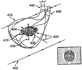
[361 The earth's magnetic field may also be used to determine golf swing
parameters.
Magnetic field sensors may be attached to or embedded within a golf club to
detect
components of the earth's magnetic field at different club locations. As shown
in Figure
4, the earth's magnetic field represented by vector 402 is relatively constant
in the
vicinity of a golfer. A magnetic field sensor 404 resolves magnetic field
vector 402 into
three component vectors 406, 408 and 410. Magnetic field sensor 404 may be
implemented with an =isotropic magnetoresistive (AMR) device, a giant
inagnetoresistor (GMR) device or other suitable devices. As golf club head 412
moves,
magnetic field vector 402 is resolved into component vectors 406, 408 and 410
such that
the respective components have different magnitudes_ The changing magnitudes
of the
component vectors may then be used to determine golf swing parameters.
[371 The club head face angle 420 may be determined by first taking a
reference measurement of the magnetic
field before the back swing (back swing position shown at 430) and then taking
another measurement of the magnetic
field just prior to impact (impact position shown at 440). For example, the
magnitude ofcomponent vectors
406, 408 and 410 will have first values before the back swing and second
values just
prior to impact. The different component vector values can then be used to
determine the
face angle. If the magnetic field in the x-y plane is assumed to be 0.3 Gauss,
the
component X of the field with respect to component vector 408 (x axis) is
determined by
X = 0.3cos0 and the component Y of the field with respect to component vector
410 (y
axis) is determined by Y = 0.3sin0.
[381 A 1 degree difference would cause a change in the magnitudes of vector
components 408
and 410 as follows:
=
AX = 0.3(cos0 ¨ cos (0+1))
AY = 0.3 (sin() ¨ sin (0+1))
[391 The smallest change that needs to be detected along each vector component
may be
determined by taking the derivative of each component and determining were the
derivative crosses the 0 axis.
dX/4310 = -0.3sin0 =0 at 0 =0 degrees
dYkl0 = 0.3cos0 =0 at 0 = 90 degrees
CA 02745593 2011-07-07
61368-1290E
8
[401 The highest resolution in the x-component is needed when the angle
rotates from 0 to 1
degree and corresponds to 45.7 G. The same resolution is needed when the y-
component rotates from 89 to 90 degrees.
[41] Swing tempo may be determined by using vector component 406 (z axis) as a
tilt sensor.
A reference measurement of vector component 406 may be recorded before the
back
swing. The period required for the club head to return to a position such that
the vector
component 406 returns to the measured reference value corresponds to the swing
tempo.
In an alternative embodiment, velocity information may also be just to
determine impact
time and the resulting swing tempo.
[42] Several different measurements may be used to determine the swing path.
Figure 5
shows a diagram of how velocity, time and orientation measurements may be used
to
determine the swing path. For example, velocity and time information
measurements
may be used to determine a first locus of points 502. Next, an orientation
measurement
may then be used to determine a first location 504 along first locus of points
502. The
process of identifying club locations may be repeated several times to
determine a swing
path 506. In one embodiment, measurements are taken at least 1 kHz during a
swing.
Swing path 506 may be determined relative to a reference orientation and
impact
location 500.
[43] Figure 6 shows an embodiment in which_ a gyroscope 602 is placed within a
golf club
head 604 to measure golf swing parameters. Gyroscope 602 may be implemented
with a
micro-electromechanical system (MEMS) or other device or module capable of
fitting
within golf club head 604. A three-axis gyroscope may be used to increase
accuracy.
= [44] Gyroscope 602 may be used to determine golf swing parameters by
assuming that the
point of rotation is a golfer's shoulders. Club head velocity may be
determined by an
accelerometer that is part of the same MEMS, an external accelerometer or some
other
device. For golf swing parameter determination purposes, in the proximity of a
ball the
movement of golf club head 604 may be modeled as an object moving on the
surface of a
sphere. The sphere has a radius equal to the length of the club plus the
length of the
golfers arms. In one embodiment, a standard radius of 62.5 inches is used.. In
other
CA 02745593 2011-07-07
61368-1290E
9
embodiments, a golfer may provide his or her arm length and/or club length for
more
accurate determinations.
1451 The face angle of golf club head 604 may be determined as a function of
the shaft
rotation rate. The shaft rotation rate may be determined by gyroscope 602.
Figure 7
illustrates one exemplary method of determining the face angle with the use of
a
gyroscope. First, in step 702 the start of the back swing is determined. A
velocity sensor
may be used to determine the start of the back swing. In step 704 impact of
the golf club
with a ball is detected. Step 704 may be performed by the impact sensors
described
above. The shaft rotational rate as a function of time may be determined by
gyroscope
604 in step 706. Step 706 preferably includes determining the shaft rotational
rate from
at least the start in step 702 until at least the impact in step 704. Next, in
step 708, the
golf club shaft rotational rate is integrated with respect to time from the
start in step 702
until the impact in step 704 in accordance with the following formula:
Impact
Face Angle Change = BackswingStart Shaft Rotation Rate (t) dt
The face angle 0 is then determined by adding the face angle change to the
original face
angle in step 710.
[461 Club head speed may be determined as a function of the radius (arm length
plus club
length) and angular velocity to. In particular, the club head speed is the
product of the
radius and the angular velocity of golf club head 604.
[47J Swing tempo may be determined by first determining when the angular rate
is zero and
begins to increase at the start of the back swing. The time of impact may then
be
determined by a spike- in the angular rate that accompanies the impact or from
one or
more other sensors, such as an accelerometer or impact sensor.
[481 Rotational velocities may also be used to determine the swing path. In
one embodiment
in which gyroscope 602 is implemented with a three axis gyroscope and in which
the z-
axis is used to determine changes in face angle, the y-axis is used to
determine motion in
a target reference plane and the x-axis is used to determine motion parallel
to the target
reference plane, the swing path may be estimated by the following formula:
CA 02745593 2011-07-07
61368-1290E
L
xAxisRotationalVelocit:y=
SwingPath =atan yAxisRotationalVelocity
[49] Figure 8 illustrates a portable computer device 802 having a graphical
user interface 804
formatted in accordance with an embodiment of the invention. A tempo bar 806
may be
included to represent the tempo of a golf swing. The center of tempo bar 806
may
correspond to an optimum tempo. A pointer 806a illustrates tempo deviation
from the
predetermined optimum tempo value. Optimum values for the variables
illustrated with
graphical user interface 804 may correspond to a particular swing selected by
a golfer.
For example, after hitting a long drive with a driver, the golfer may
configure portable
computer device 802 to use all of the variables from that golf swing as
reference points.
The configuration may be performed by selecting a menu option. Of course
portable
computer device 802 may be programmed with optimal values that are suitable
for many
golfers.
[50] A grip pressure bar 808 may be included to display grip pressure relative
to an optimal
value. A shaft energy transfer bar 810 may be included to illustrate the
deviation of shaft
energy transfer from a predetermined optimal value. Shaft energy transfer is a
function
of the distance of the club head relative to the club shaft centerline. In one
embodiment
of the invention, accelerometer module 204 may be used to determine a location
of the
club shaft and accelerometer module 212 may be used to determine the location
of the
club head. The distance between the club head and club shaft centerline just
prior to
impact with the golf ball may be used to determine shaft energy transfer.
Relative club
speed and weight transfer may be displayed with menu bars 812 and 814
respectively.
Weight transfer is defined as a percentage of weight that is transferred from
the rear foot
to the front foot during a golf swing. Of course numerous additional or
alternative
variables may be detected by sensors that are a part of golf club 200 (shown
in Figure 2)
and those variables may be represented on graphical user interface 804.
[51] Figure 9 illustrates a method of providing golf swing data to a golfer.
First, step 902 a
portable computer device receives golf swing data. Step 902 may include
receiving data
corresponding to the golf swing from an instrumented golf club. Next, in step
904 a
CA 02745593 2011-07-07
61368-1290E
11
portable computer device receives an indication that the golf swing is a
preferred golf
swing. For example, after hitting a drive that the golfer is pleased with, the
golfer may
select an item on a user interface screen to indicate 1-1iq the golf swir.g,
is a prefen-ed golf
swing. Similarly, the golfer many indicate that other golf swings are
preferred golf
swings for various other clubs and situations. In one embodiment, the golfer
may
indicate select preferred golf swings that correspond to each club the golfer
carries.
[52] Next, in step 906 the golf swing data corresponding to the
preferred golf swing is stored
as preferred golf swing data. The preferred golf swing data may include values
of
variables such as tempo, grip pressure, shaft energy transfer, club speed,
club face angle,
swing path, impact location and weight transfer. The preferred golf swing data
may later
be used as a reference when analyzing other golf swings. For example, after
hitting a
drive that the golfer wishes to use as a reference, a club head speed of 125
mph that was
measured during the swing may be stored as a preferred value. That is, the
preferred
value of the club head speed parameter would be set to 125 mph. In step 908
the
portable computer device may receive golf swing data from a self-contained
instrumented golf club. The self-contained instrumented golf club may be
similar to the
golf club described above and the golf swing may be a golf swing made during
an actual
round of golf. The portable computer device may also receive weight transfer
data from
a weight transfer module in step 910. The data received in steps 908 and 910
may be
received using one of the wireless transmission methods and protocols
described above.
[53] In step 912 at least some of the golf swing data and weight transfer data
is displayed in
real-time on a portable computer device in relation to preferred golf swing
and weight
transfer data. Step 912 may include displaying the data on a user interface
such as the
user interface shown in Figure 8.
[54] One skilled in the art will appreciate that aspects of the present
invention may be used in
connection with several different user interfaces. Figure 10, for example,
illustrates a
portable computer device 1002 having a graphical user interface 1004 that
allows a user
to select a baseline or preferred swing, in accordance with an embodiment of
the
invention. User interface 1004 allows a golfer to select a baseline swing by
selecting an
appropriate radio button in column 1006. The entries displayed in column 1008
may
correspond to golf swings that occurred at different courses on different
dates.
CA 02745593 2012-04-30
61368-1290E
12
Alternatively, a golfer may store baseline swings for different conditions or
golf clubs.
Exemplary entries that may be included in column 1008 include "high wind,"
"from
fringe," "3 iron," and "Colonial CC ¨ 46 hole." The golfer's name may be
identified in
region 1010.
[55] After selecting a particular entry with graphical user interface 1004, a
golfer may then be
presented with a graphical user interface that displays baseline golf swing
parameters.
Figure 11 shows graphical user interface 1102 including baseline or preferred
values in
accordance with an embodiment of the invention. The four parameters shown are
face
angle, club speed, impact location and tempo. The baseline impact location
corresponds
to highlighted square 1104, the baseline tempo is 1.1 seconds, etc. Of course
additional
or alternative parameters may be displayed. In one embodiment of the
invention, the
parameters displayed are a function of the entry sele,cted.
[56] Figure 12 illustrates a graphical user interface 1202 that displays golf
swing data for one
or more golf swings against baseline golf swing parameter values. The number
of golf
swings may be displayed in region 1204. The golfer may be allowed to discard
golf
swing data for one or more golf swings. For example, if the golfer has a
particularly bad
swing the corresponding data may not be relevant and may be discarded. User
interface
1202 may be configured to allow the golfer to see regions 1206, 1208, 1210 and
1212 in
greater detail. For example, selecting region 1210 may cause graphical user
interface
1302 (shown in Figure 13) to be displayed.
[57] Graphical user interface 1302 includes a grid overlying the face of a
golf club. Numbers
may be added to regions to indicate the number of times the regions
corresponded to
impact location. For example, region 1304 corresponded to the impact location
during
two golf swings. A data selection region 1306 may be included to allow the
golfer to
view other golf swing parameter values.
[58] While the invention has been described with respect to specific examples
including
presently preferred modes of carrying out the invention, those skilled in the
art will
appreciate that there are numerous variations and permutations of the above
described
systems and techniques that fall within the scope of the invention as set
forth in
the appended claims.