Note: Descriptions are shown in the official language in which they were submitted.
CA 02745611 2011-07-07
MOBILE DEVICE CASE
TECHNICAL FIELD
[0001] The present disclosure relates to cases for electronic mobile
devices.
BACKGROUND
[0002] With their increasing power and functionality, mobile devices such
as handheld electronic devices are being relied upon in an increasing number
of
applications and environments. In certain environments, it is desirable to use
a
mobile device without the user having to physically hold the device, such as
when the mobile device is laying on a flat surface or in a cradle.
SUMMARY
[0003] According to one example is a removable case for a mobile device,
the mobile device having a front face and a side edge, and an input button
located on the side edge. The case includes a main body defining a region in
which the mobile device can be removably received, and an actuator on the
main body having a user interface and a button interface. The input button is
activated by the actuator translating an input force received on the user
interface into a button activating force applied by the button interface, the
button activating force being applied in a different direction than the input
force.
[0004] According to another example is a handheld unit that includes a
handheld electronic mobile device and a removable case receiving the mobile
handheld electronic device. The mobile device has a display screen on a front
face of a housing thereof, the housing having opposite side edges that are
substantially perpendicular to the front face, and a first input button on one
of
the side edges that is depressible towards an interior of the housing. The
removable case includes a main body defining a region in which the mobile
device is removably received with the display screen being viewable, and an
actuator on the main body having a user interface and a button interface,
wherein the actuator translates an input force that depresses the user
interface
in a direction towards the display screen into a button activating force
applied by
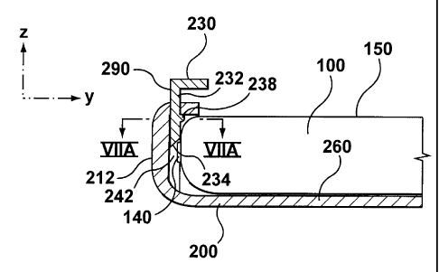
CA 02745611 2011-07-07
the button interface on the first input button, the activating force being
substantially orthogonal to the input force.
BRIEF DESCRIPTION OF THE DRAWINGS
[0005] Embodiments will now be described, by way of example only, with
reference to the attached Figures, wherein:
[0006] Figure 1A is a front view of an example of a mobile device to which
examples of a mobile device case may be applied;
[0007] Figure 1B is a back view of the mobile device of Figure 1A;
[0008] Figure 1C is a right side view of the mobile device of Figure 1A;
[0009] Figure 1D is a left side view of the mobile device of Figure 1A;
[0010] Figure 2 is a perspective view of an example of a case for a mobile
device such as the device of Figure 1A;
[0011] Figure 3 is a front view of the case of Figure 2;
[0012] Figure 4 is a sectional view of the case of Figures 2 and 3, taken
along the lines IV-IV of Figure 3;
[0013] Figure 5 is a front view of a mobile device inside the case of Figure
2;
[0014] Figure 6A is a cross-sectional view of part of the case taken across
lines VI-VI in Figure, 5 when an actuator on the case is in a normal position,
according to one example;
[0015] Figure 6B is same view as 6A, but showing the actuator is in an
actuated position;
[0016] Figure 7A is a partial sectional view showing part of the case taken
across lines VIIA-VIIA of Figure 6A;
-2-
CA 02745611 2011-07-07
[0017] Figure 7B is a partial sectional view showing part of the case taken
across lines VIIB-VIIB of Figure 4;
[0018] Figure 8A is a side view of an example of an actuator that can be
integrated into the case of Figure 2;
[0019] Figure 8B is an end view of an example of the actuator of Figure
8A;
[0020] Figure 9A is a cross-sectional view of another example of a case
with a mobile device as seen from line VI-VI in Figure 5 when an actuator on
the case is in its normal position; and
[0021] Figure 9B is the same view as 9A, but showing the actuator in an
actuated position.
[0022] Like reference numerals are used throughout the Figures to denote
similar elements and features.
DETAILED DESCRIPTION
[0023] As users carry their mobile devices with them throughout their daily
activities, these devices are often dropped or scratched, and are subject to
spilled liquids, dust, and general wear and tear. For protective or acetic
purposes, users often cover their mobile devices, such as handheld electronic
devices, with a case often referred to as a device case or skin. Generally,
these
cases are specifically designed to fit a specific device make and model.
Mobile
devices which commonly use cases include mobile smart phones, text and email
messages devices, portable audio and video players, Global Positioning System
(GPS) navigation devices, personal digital assistants (PDAs), electronic book
readers, cameras, and portable video game players; however, these cases could
be applied to any mobile device.
[0024] In accordance with one example is a case for a mobile device, the
mobile device having a front face facing a Z-direction, and a side-edge that
is
substantially orthogonal to the front face, facing an X- or a Y-direction. An
input
-3-
CA 02745611 2011-07-07
button is located on the side edge of the mobile device, and the case includes
a
main body having a mobile device accommodating portion into which the mobile
device is insertable. The case also includes an actuator that orthogonally
translates force in the Z-direction to an X- or Y-direction for activating the
input
button.
[0025] Reference is made to Figures 1A-1D which show an example of a
mobile device 100 to which examples of mobile device cases described herein
can be applied. In Figures 1A-1D, the mobile device 100 is a handheld
electronic
device such as, for example, a mobile smart phone with a housing 110, a
display
screen 120, front buttons 130, and a plurality of side buttons 140, 142, 144.
The
housing 110 houses the electronic components of the mobile device 100 and
has a front face 150, a back side 160, and left, right, top and bottom side
edges
170, 172, 174 and 176, respectively. The front face 150 includes the display
screen 120 and the front buttons 130 which may be arranged in the form of a
keypad or keyboard 132. The front face 150 faces the Z-direction and is
substantially parallel to back side 160. Users will typically view or access
the
device from an angle incident to the front face 150. The side button 140, as
illustrated, is on the left side edge 170 which is substantially orthogonal to
the
front face 150. Side buttons 142, 144 are on a right side edge of the device
housing 110 which is substantially orthogonal to the front face 150. In the
illustrated embodiment the side button 140 is on a longitudinally extending
left
side edge of the housing, facing the Y-direction, and the side buttons 142,
144
are on a longitudinally extending right side edge of the housing 110, facing
the
opposite Y-oriented direction; however, the side buttons could be on any of
the
side edges including the top or bottom side edges in addition to left and
right
side edges and could face any direction substantially parallel to the X-Y
plane
and orthogonal to the front face 150.
[0026] The mobile device 100 could in various examples have many
alternative numbers or arrangement of front buttons 130 and side buttons 140,
142, 144. These buttons are generally activated by a force applied by the user
to
push the button from its original position into the device housing 110.
Activating
a button results in an input to the mobile device 100 and may result in a
visual,
audible or tactile feedback response. Once the activating force is removed
from
-4-
CA 02745611 2011-07-07
a button, an elastic or other mechanical mechanism will force the button out
of
the housing and back to its original position.
[0027] Depending on the type of mobile device, the housing 110 may
contain a number of internal components to control the functioning of the
device
and to respond to user input such as a button press. For example, in a mobile
smart phone, the housing 110 may contain a controller comprising at least one
processor (such as a microprocessor) which controls the overall operation of
the
device 100. The processor may interact with device subsystems such as a
wireless communication subsystem for exchanging radio frequency signals with a
wireless network to perform communication functions. The processor may
interact with additional device subsystems including the display screen 120
such
as a liquid crystal display (LCD) screen, input devices such as front buttons
130
and side buttons 140, 142, 144, flash memory, random access memory (RAM),
read only memory (ROM), auxiliary input/output (I/O) subsystems, data ports,
speakers, microphones, short-range communication subsystems, and other
device subsystems.
[0028] In one example, the side button 140 is configured to activate a
"voice input" function on the device 100 in which voice inputs are converted
to
text - for example a voice dialling function. In another example, side button
140
is configured as a "push-to-talk" key for device to device communications. In
some examples, side buttons 142 and 144 are configured as volume control
buttons for the device - for example activating upper side button 142 raises
an
output volume, and activating lower side button 144 lowers an output volume.
Visual feedback, for example volume bars, may be provided on display screen
120 to indicate a relative volume setting when buttons 142 or 144 are
activated.
In some examples, the functionality provided by side buttons 140, 142 and 144
can be application specific.
[0029] The housing 110 could also include any number of external
interfaces such as screens, video/audio ports 152, power ports, USB/data ports
154, camera lenses, camera flash, indicator lights, speakers, microphones,
antennae, or air vents.
-5-
CA 02745611 2011-07-07
[0030] Figures 2, 3 and 4 illustrate an example of a removable mobile
device case 200 which can be applied to the mobile device 100 in Figure 1.
Figure 5 illustrates an example of a handheld unit that includes the mobile
device case 200 mounted on mobile device 100. The mobile device case 200 has
a main body 210 for accommodating the mobile device 100. The shape and size
of the main body 210 is generally designed to fit a specific model of device.
The
main body 210 may for example be configured to cover substantial portions of
the housing 110 of the mobile device 100 to protect it from dents, scratches
and
general wear and tear. In the illustrated example, the main body 210 of case
200 includes a planar base panel 260, a right side panel 214 extending forward
from a longitudinal right peripheral edge of the base panel 260, a left side
panel
212 extending forward from a longitudinal left peripheral edge of the base
panel
260, a top side panel 218 and a bottom side panel 216. In some examples,
inwardly projecting front flanges 250 and 252 that are substantially parallel
to
the base panel 260 may be provided on the forward edges of left side panel 212
and right side panel 214 respectively.
[0031] The base panel 260 and side panels 212, 214, 216 and 218
collectively define an internal cavity or region 220 for receiving the mobile
device
100. In one example, the main body 210 is made as a single unit formed of a
rigid material such as ABS plastic or other plastic, or metal, that can be
temporarily deformed to fit the main body 210 onto the mobile device 100 such
that the mobile device 100 is received within cavity 220 with the mobile
device
back side 160 facing the base panel 260, and the left and right side panels
212
and 214 gripping the opposite side edges 170, 172 of the mobile device 100. In
some alternative examples, the main body 210 can be formed from less rigid
materials such as silicon or rubber, or may be formed from combinations of
rigid
and flexible materials - for example, the main body may include an inner skin
formed from silicon that is secured to an outer rigid body formed from plastic
or
metal.
[0032] In various examples, the case 200 may also come in a variety of
colours or designs, and can even include decals or pictures to add a
decorative
or expressive element to the case 200.
-6-
CA 02745611 2011-07-07
[0033] In the illustrated example, the deformable main body 210 of the
case 200 defines a front opening 280 to the region 220 to provide access to at
least some of the user interfaces of the mobile device 100, and also to allow
the
mobile device 100 to be inserted into the case 200. For example, the opening
280 is configured to allow a user to view the display screen 120, and provide
access to user inputs such as buttons 130 that are located in the keyboard 132
on the face of mobile device 100. In some embodiments, the case 200 may
include a translucent or transparent window material over opening 280 which
provides protection to the mobile device 100 while allowing the user to see
and
interact with interfaces such as the display screen 120. If the screen 120 is
a
touchscreen, the window material may be thin enough to allow the user activate
the touchscreen through the window.
[0034] In some examples, external interfaces such as buttons may be
covered by the case 200. To provide access to these buttons, the case may
include visual aids or corresponding button extensions to indicate to the user
the
location of the underlying device buttons.
[0035] In some examples, the case may be designed to accommodate a
device with moving parts such as a flip phone, slider phone, or camera lens.
In
some examples, the case could have a flap which may be folded over to protect
the device's external interfaces such as a screen when the device is not in
use.
The flap can be opened when the user again wishes to access the external
interfaces covered by the flap.
[0036] In an example, the case 200 includes actuators 290, 292 and 294
integrated with the main body 210 for respectively activating device side
buttons
140, 142, 144. Referring to Figures 3 and 4, in the illustrated example,
actuators
290, 292 and 294 extend forward from the main body 210 along the Z-axis and
each have a respective forward facing physical user interface 230, 232, 234
that
is substantially parallel with the front face 150 of the mobile device 100)
for
receiving a force in the Z-direction. When pressed, the actuators 290, 292 and
294 each orthogonally translate a force in the Z-direction (e.g. towards the
front
face 150 of the mobile device 100) to a perpendicular force in the X- or Y-
direction (e.g. towards the side edges 172, 174) depending on the actuator's
orientation on the perimeter of the case 200.
-7-
CA 02745611 2011-07-07
[0037] Referring to Figure 5, when a device 100 is placed in the case 200,
the actuator 290 is proximally aligned with side button 140, actuator 292 is
proximally aligned with side button 142 and actuator 294 is proximally aligned
with side button 144. While the Figures show only three actuators 290, 292,
294, the case 200 may have any number of integral buttons located around its
perimeter of the front face 250 to correspond to device side buttons that are
desired to be activatable from the Z-direction.
[0038] An example of actuator 290 will now be explained in greater detail
with reference to Figures 6A, 6B, 7A, 7B, 8A and 8B. The actuator 290 includes
a
shaft 232 that has physical user interface 230 at one end thereof and a
chamfered button interface 234 at an opposite end thereof. In one example, the
physical user interface 230 takes the form of an enlarged head portion
providing
a pushable key surface. The user interface 230 is fixed at a substantially
right
angle (see for example Figure 8B) to a forwardly extending end of the shaft
232.
In an example, physical user interface 230 is large enough that it can be
pressed
by a user who has reduced physical capabilities but small enough so as to not
impede viewing of the device display screen. As seen in Figures 7A and 7B, in
one example, the actuator shaft 232 passes through and is slidable within a
slot
236 that is provided in an upper portion of the side panel 212, with the
chamfered button interface 234 being received within a recess 242 that is
provided in the side panel 212. A protrusion 238 can be provided on the shaft
232 to limit the movement of the actuator 290 along the Z-axis away from the
front face 150 of the mobile device 100.
[0039] Referring to Figures 6A and 6B, operation of the actuator 290
according to an example will now be described. In Figures 6A and 6B, the
mobile
device 200 may for example be lying on a horizontal flat surface such as a
table
or desk top, or mounted in a cradle. Figure 6A shows the actuator 290 in a
first
or normal resting position in which the chamfered button interface 234 is
positioned to contact a forward edge of button 140, and the physical user
interface 230 is spaced apart from the front surface 150 of the mobile device
100. In Figure 6B, the actuator 290 has been depressed into an activated
position by a force applied on the physical user interface 230 in the Z
direction.
The Z-direction force is orthogonally translated at the chamfered button
-8-
CA 02745611 2011-07-07
interface 234 into a Y-direction force that displaces the device side button
140 in
the Y direction towards an interior of the mobile device 100. In one example,
the
physical user interface 230 comes into contact with the front flange 250 of
the
case body when the actuator 290 is in its activated position as shown in
Figure
6B, limiting further depression of the actuator 290. The actuator 290 will
remain
in the position shown in Figure 6B until pressure is removed from the physical
user interface 230, after which the actuator 290 and side button 140 move back
to their normal resting position as shown in Figure 6A. In one example, the
force
of side button 140 pushing on chamfered button interface 234 provides force
for
moving the actuator 290 from its activated position shown in Figure 6B back to
its normal resting position shown in Figure 6A, and biasing the actuator into
its
normal resting position until an external activating force is applied to it.
[0040] In some examples, a resilient deformable portion of the resilient
side panel 212 near the actuator 290 is deformed from a normal position as the
actuator 290 is moved into the actuated position. When the activating pressure
is subsequently removed from actuator 290, the resilient deformable portion of
side panel 212 moves back to its normal position under elastic forces thereby
providing force for moving the actuator 290 from its activated position shown
in
Figure 6B back to its normal resting position shown in Figure 6A. Accordingly,
in
some examples, the side panel 212 biases the actuator 290 into its normal
resting position until an external activating force is applied to it. The
protrusion
238 limits the outward movement of the actuator 290 once it has reached its
normal outer position. In some examples, portions of the side panel 212 may be
thicker or reinforced in the vicinity of the actuator 290 to provide rigidity
to
support the side panel 212 as the actuator 290 is pressed.
[0041] In the illustrated example, actuators 292 and 294 are substantially
identical in configuration and operation to actuator 290.
[0042] Accordingly, actuators 290, 292 and 294 allow a user to press
towards the front face of the device 100 to activate side buttons on the
device
100. Among other things, such a feature may be useful for users who need to
lie
the device 100 down on a flat surface or secure the device in a cradle to use
the
device, including users who have physical limitations that would inhibit
conventional hand held use of the device 100.
-9-
CA 02745611 2011-07-07
[0043] To prevent the device from slipping when the user presses an
actuator 290, 292, 294 the base panel 260 of the device may be composed of a
non-slip material which will create a resistance to sliding along a smooth
surface.
The non-slip material may also make the device easier or more comfortable to
hold.
[0044] In some examples, the base panel 260 of the case 200 may be
designed to prevent the device from tipping when it is laid on a flat surface.
Mobile devices are often designed with bevelled or curved edges which may
increase the aesthetic appeal of the device. However, these edges may allow
the
device to tip when a force in the Z-direction is applied near the edge of the
device. In some embodiments, the base panel 260 of the case 200 may be
designed to sit flush with a flat surface to reduce the chance of tipping.
[0045] In some examples, the base panel 260 of the case 200 may extend
in the X- or Y-direction away from the edge of the device. For example,
outwardly extending flanges 293 (shown in dashed lines on Figure 4) may be
integrally formed around peripheral edges of the base panel 260 to engage the
support surface on which the mobile device 100 rests and provide stabilization
to
prevent the mobile device 100 from tipping over as the actuators 290, 292, 294
are pressed.
[0046] Another example of an actuator configuration is shown in Figures
9A and 9B in which the integral actuator 290' has a receiving physical user
interface 510 and a button interface 520 connected at substantially right
angles
to each other and secured to the side panel 212. The user interface 510 and
button interface 520 are coupled such that when a force in the Z-direction Fz
is
applied to the user interface 510, the actuator 290' rotates causing the
button
interface 520 to exert a force in the Y-direction on the side button 140.
Figure
9A illustrates this embodiment with the actuator 290' in its normal resting
position. In Figure 9B, the user is exerting a force in the Z-direction Fz on
the
user interface 510 causing a rotation of the actuator 290' which in turn
creates a
force in the orthogonal or Y-direction Fy on the side button 140. In one
example,
once the external force Fz is removed, the actuator 290' is returned from the
activated position of Figure 9B to its normal resting position seen in Figure
5A,
by the movement of the elastically deformable material of side panel 212 back
to
-10-
CA 02745611 2011-07-07
its original shape, or backpressure from the side button 140, or a combination
of
both.
[0047] In some examples, the case 200 may include a spring that is
compressed when the actuator is actuated and which subsequently provides a
force to return the actuator to its original resting position.
[0048] In some embodiments, the actuators 290, 290', 292, 294 will not
limit the ability of the user to apply a force in the X- or Y-direction to
directly
activate the side buttons without translating the direction of the force.
[0049] In the embodiments and drawings described above, the sides and
front face of the mobile device have been illustrated as being somewhat
orthogonal, however, it would be understood by a person skilled in the art
that
depending on the design of the mobile device, the embodiments of the current
disclosure can be designed to translate a force from any direction to any
other
direction to activate a button on the device, and is not limited to the
situation
where the two directions are orthogonal.
[0050] At least some examples described herein relate to a removable case
200 for use with a mobile device 100 that has a front face 150 and a side edge
170, and an input button 140 located on the side edge. In at least some
examples, the removable case 200 includes a main body 210 defining a region
260 in which the mobile device 100 can be removably received. An actuator 290
on the main body 210 has a user interface 230 and a button interface 234. The
input button 140 is activated by the actuator 290 translating an input force
received on the user interface 230 into a button activating force applied by
the
button interface 234 (for example a Z-direction force), the button activating
force being applied in a different direction (for example a Y-direction) than
the
input force. Accordingly, as noted above, in some examples actuators 290, 292
and 294 allow a user to press towards the front face of the device 100 to
activate side buttons on the device 100. Among other things, such a feature
may
be useful for activating side buttons on a device 100 that is lying face up on
a
flat surface flat surface or secured in a cradle, and could be useful to users
who
have physical limitations that would inhibit conventional hand held use of the
device 100.
-11-
CA 02745611 2011-07-07
[0051] The above-described embodiments of the present application are
intended to be examples only. Alterations, modifications and variations may be
effected to the particular embodiments by those skilled in the art without
departing from the scope of the application, which is defined by the claims
appended hereto.
-12-