Note: Descriptions are shown in the official language in which they were submitted.
CA 02745621 2011-06-02
SPECIFICATION
SYRINGE
TECHNICAL FIELD
[0001] The present invention relates to a syringe, and more particularly
relates to a
syringe which is excellent in terms of accuracy of visual inspection of the
content and a
prefilled syringe filled with a high viscosity drug that are suitable for
injection of high
viscosity drugs.
BACKGROUND ART
[0002] In recent years, prefilled syringes prefilled with drugs have been used
for
reasons such as prevention of mistakes during medical treatment and prevention
of
bacterial contamination. A prefilled syringe has the tip opening of a barrel
sealed with
a cap member, is filled with a drug inside the barrel, has the rear end
portion of the
barrel sealed with a gasket, and is transported and stored in that state. When
administering, an injection needle or an apparatus for administration is
attached to the
tip of the barrel, and by pushing a plunger attached to the gasket towards the
tip and
sliding the gasket inside the barrel, the drug flows out from the injection
needle and is
administered. As such, prefilled syringes have various advantages, such as
allowing
drugs to be administered in accurate doses without mistakes even during
emergencies as
there is no need to prepare the drugs at the point of treatment, being highly
sanitary as
there is no transferring of drugs, and being easy to operate.
[0003] Since prefilled syringes are stored and circulated in a state of being
filled with a
drug, it may be several years from the filling of the drug in production
factories to
administration. As such, while it goes without saying that long-term stability
is needed,
it is also necessary to be able to confirm the safety of the drug by visually
inspecting for
contamination by impurities. For that reason, the material constituting the
barrel needs
to be highly transparent, and barrels made of glass, which ensures
transparency, have
been frequently used in conventional prefilled syringes.
Ni
CA 02745621 2011-06-02
-2-
[0004] However, glass barrels crack relatively easily, need to be separated
from the
other parts and cannot be incinerated together therewith when discarded, and
cost more,
so there has been a demand for barrels made of resin. Resins with transparency
comparable to that of glass barrels have appeared in recent years, and there
has been a
gradual transition towards resin barrels.
[0005] Regardless of the material of the barrel, to ensure sufficient
slidability between
the barrel and gasket, a lubricant layer composed of silicone or the like is
generally
provided on the inner peripheral surface of the barrel and/or the outer
peripheral surface
of the gasket.
[0006] In the case of conventionally used glass barrels, typically, silicone,
in the form of
an emulsion, is applied to the inner peripheral surface of the barrels and is
fixed by
baking at a high temperature (200 to 300 C). Silicone in itself is not
harmful to the
human body, but the silicone is fixed to the inner peripheral surface of the
barrels to
avoid the silicone contaminating the drugs.
[0007] In the case of resin barrels, since the glass transition point of
resins is lower than
the baking temperature of silicone, the same fixing treatment as for glass
barrels cannot
be used. In the case of resin barrels, methods in which a radiation or
ultraviolet-curable
organopolysiloxane is used and methods in which a photopolymerization catalyst
such
as benzophenone is added to silicone have been proposed as examples of methods
for
fixing silicone instead of baking at a high temperature (Patent Document 1).
[0008] On the other hand, as methods not involving such a fixing treatment,
methods
in which a silicone oil is simply applied to the inner peripheral surface of a
barrel have
also been widely used. In particular, in order to prevent the silicone oil
from dripping
from the inner peripheral surface of the barrel and contaminating the drug and
to
suppress increases in the sliding resistance of the gasket, the addition of a
fine silica
powder to a silicone oil has been proposed (Patent Document 2).
[0009] Additionally, in order to ensure sufficient slidability between the
barrel and
gasket, a prefilled syringe involving the use of a sealing stopper (gasket)
for a syringe,
which is a rubber stopper with its surface laminated with a
tetrafluoroethylene resin film
or an ultrahigh molecular weight polyethylene film, has also been proposed
(Patent
Document 3).
Patent Document 1: JP-A 2007-244606
CA 02745621 2011-06-02
-3-
Patent Document 2: JP-A 2006-94895
Patent Document 3: JP-A H10-314305
SUMMARY OF THE INVENTION
[0010] However, since methods for the lubrication treatment of resin barrels
comprising fixation require a step of curing by radiation etc. as described in
the above
Patent Document 1, production efficiency is inevitably poor. Additionally,
some curing
agents etc. may affect the human body when contaminating a drug.
[0011] On the other hand, when the fixing treatment is not performed,
naturally, there
is a risk of the applied silicone oil separating from the inner peripheral
surface of the
barrel during filling of a drug, storage or transport and contaminating the
drug, causing
turbidity. This is, as described in the above Patent Document 2, not a problem
that can
be completely overcome even when, for example, the silicone oil contains a
fine silica
powder. Rather, in that case, there is a risk of not only the silicone oil,
but also the fine
silica powder contaminating the drug.
[0012] Such contamination by the silicone oil from the inner peripheral
surface of the
barrel is particularly notable when the viscosity of the drug is high. While
the exact
mechanism is unclear, this is thought to be due to the high shear stress
exerted on the
silicone oil adhering to the inner peripheral surface of the barrel when
filling the syringe
with a drug of high viscosity. As mentioned above, silicone oil is not
necessarily
harmful to the human body, but it is not possible to clearly distinguish
between turbidity
caused by contamination due to silicone oil and turbidity caused by
substantial
contamination due to impurities by visual inspection alone, so such syringes
may be
determined to be defective products during inspection or medical practice and
be forced
to be discarded without ever being used.
[0013] Further, even when the silicone oil adheres normally to the inner
peripheral
surface of the barrel, the refractive index of the applied silicone oil
differs from the
refractive index of the drug and the refractive index of the synthetic resin
constituting
the syringe, resulting in glare on the inner peripheral surface of the barrel,
which may
interfere with visual inspection or make it seem as if there has been
contamination by
impurities or a defect such as a scratch on the barrel.
CA 02745621 2011-06-02
-4-
[0014] Moreover, in the case of the sealing stopper (gasket) for a syringe
described in
Patent Document 3, since the surface of the rubber stopper is laminated with a
resin film,
the error in the inner diameter of the sealing stopper (gasket) for a syringe
or the barrel
could be increased due to the disparity of the actual dimensions with respect
to the
dimensions of the original design, and there tended to be problems in the
slidability or
sealing properties of the sealing stopper (gasket) for a syringe with respect
to the inner
surface of the barrel.
[0015] As such, there has been a need for syringes capable of reducing the
risk of
separation and contamination by silicone oil while not requiring fixation of
the silicone
oil, in which glare rarely occurs on the inner peripheral surface of the
barrel, and
equipped with sufficient gasket slidability and sealing properties.
[0016] The present invention was achieved in view of the above circumstances,
with an
object of providing a syringe excellent in inspection accuracy while ensuring
slidability
and sealing properties between the barrel and gasket, and in particular, a
syringe that is
also suitable for filling with a high viscosity drug.
[0017] As a result of diligent studies, the present inventors found that by
spraying a
silicone oil of a predetermined kinematic viscosity onto the inner peripheral
surface of a
resin barrel at a predetermined application amount per unit area, it is
possible to
suppress separation and contamination by the silicone oil and glare on the
inner
peripheral surface of the barrel in addition to providing sufficient
slidability.
[0018] That is, the syringe of the present invention is characterized by
having a resin
barrel, a gasket slidably inserted in the barrel, a plunger attached to the
gasket, and a
silicone film formed by applying a silicone oil having a kinematic viscosity
of 500 to
100,000 cSt to the inner peripheral surface of the above-described barrel in
an amount of
to 50 g per 1 cm2 of area.
[0019] Since a silicone oil having a kinematic viscosity of at least 500 cSt
is used as the
silicone constituting the silicone film in this syringe, when spraying the
silicone oil, the
silicone oil is appropriately maintained on the inner peripheral surface of
the barrel
without running. For that reason, even when a small amount of silicone oil is
applied,
it is possible to ensure sufficient slidability with the gasket. Additionally,
since a
silicone oil having a kinematic viscosity of at most 100,000 cSt is used, it
can be applied
to the inner peripheral surface of the barrel by spraying, and the silicone
oil can be
CA 02745621 2011-06-02
-5-
evenly applied in the above predetermined application amount per unit area.
[0020] Further, by using a silicone oil having a kinematic viscosity within
that range, it
is possible to ensure sufficient slidability between the barrel and gasket
even when the
amount of the silicone oil applied is at most 50 g per 1 cm2 of area on the
inner
peripheral surface of the barrel, and the amount of the silicone oil applied
can be
suppressed to a low amount. As a result thereof, when filling with a drug,
even if the
silicone oil becomes mixed into the drug, the amount of contamination can be
kept
extremely low. As such, the occurrence of turbidity due to contamination by
the
silicone oil can be suppressed, the causes of turbidity in a drug in a
prefilled syringe can
be limited to cases of contamination by impurities other than silicone oil,
and accuracy in
visual inspection to ensure safety can be substantially improved. This is
particularly
applicable to cases where a high viscosity drug which is susceptible to
contamination by
silicone oil is loaded. Further, when the application amount is within this
range, as
long as observation is performed by the naked eye, there is also a low
likelihood of glare
being detected on the inner peripheral surface of the barrel. Moreover, when
the
amount of the silicone oil applied to the inner peripheral surface of the
barrel is at least 5
g per 1 cm2 area, sufficient slidability between the barrel and the gasket can
be ensured.
[0021] Since the viscosity of a silicone oil having a kinematic viscosity
within the above
range is high, it is generally not easy to evenly spray the oil. However, even
spraying is
possible by appropriately adjusting the liquid temperature, air pressure,
nozzle diameter
and application time etc. In particular, a fine mist can be sprayed to achieve
an
extremely thin film such as one within the above range by heating the silicone
oil within
such a range as not to cause denaturation at the time of spraying.
[0022] Moreover, by designing the maximum outer diameter of the gasket to be
greater
than the inner diameter of the barrel such that the difference between the
maximum
outer diameter of the gasket and the inner diameter of the barrel is at least
0.02 mm and
at most 0.50 mm, it is possible to suppress drug leakage from the gap between
the gasket
and barrel while maintaining the sealing properties of the gasket and ensure
sufficient
slidability between the barrel and gasket.
[0023] Further, as a result of diligent studies, it was found that when, upon
shining
incident light with an optical axis orthogonally intersecting the central axis
of the barrel
and measuring the angle of refraction from the optical axis of the transmitted
light
CA 02745621 2011-06-02
-6-
scattered along the same direction as the central axis, glare on the inner
peripheral
surface of the barrel can be remarkably suppressed if the angle of refraction
is within a
predetermined range.
[0024] That is, it was found that the glare could be remarkably suppressed
when, upon
shining an incident beam with a wavelength of 635 nm to 690 nm and a beam
width of at
most 3.0 mm on a barrel filled with a drug at an optical axis orthogonally
intersecting the
central axis of the barrel, the angle of refraction from the optical axis of
the transmitted
light scattered in the same direction as the above-described central axis was
within a
range of 0.1 to 0.5 .
[0025] The "angle of refraction" in the present invention refers to the
aperture angle
from the optical axis of transmitted light scattered along the same direction
as the central
axis of the barrel of a prefilled syringe filled with a drug when shining an
incident beam
with an optical axis orthogonally intersecting the central axis of the barrel.
The barrel of a prefilled syringe will cause a transmitted beam in a direction
perpendicular to the central axis to be highly refracted with the center of
curvature as the
central axis. Accordingly, refraction occurring in the direction perpendicular
to the
central axis is affected by solely the shape of the barrel, and cannot
indicate small
variations in the application state of the silicone oil on the inner
peripheral surface of the
barrel. On the other hand, as the barrel is not substantially curved in the
direction of
the central axis, the divergence from the optical axis occurring in the same
direction as
the central axis, i.e. the "angle of refraction" in the present invention, is
not significantly
affected by the shape of the barrel, and can directly reflect the state of
application of the
silicone oil.
[0026] It was found that when the angle of refraction of a prefilled syringed
filled with
a drug is within the range of 0.1 to 0.5 , as long as the observation is
performed by the
naked eye, there is an extremely low likelihood of glare being detected on the
inner
peripheral surface of the barrel. As such, a prefilled syringe having such an
angle of
refraction can remarkably improve the visual inspection accuracy of the drug.
[0027] According to the present invention, a drug can be more stably stored in
the
barrel and the accuracy of inspection of the content can be substantially
improved while
ensuring the sealing properties and the slidability between the barrel and
gasket. This
makes safe and accurate operation possible. As such, the syringe according the
present
Ni
CA 02745621 2011-06-02
-7-
invention has great utility as a medical apparatus and as a cosmetic
apparatus.
BREIF DESCRIPTION OF THE DRAWINGS
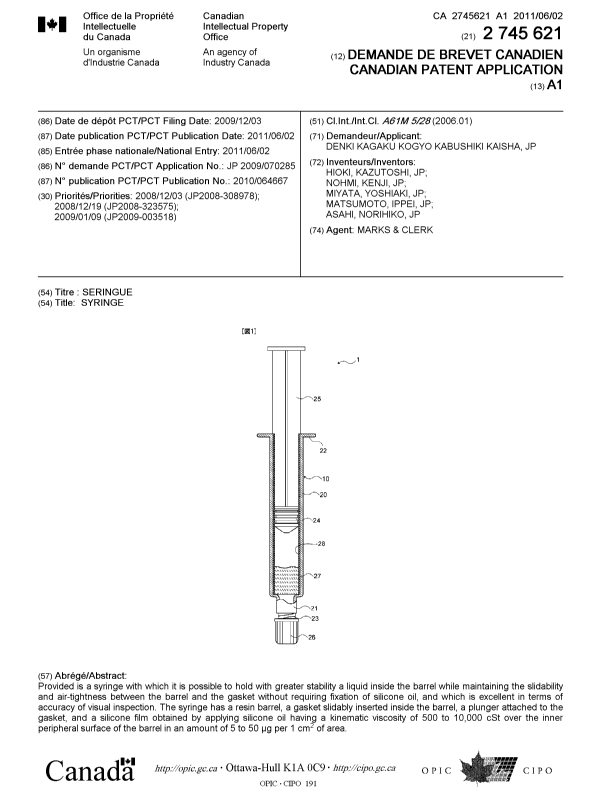
[0028] [Fig. 1] A schematic view of a prefilled syringe according to an
embodiment of the
present invention.
[Fig. 2] A schematic view showing an embodiment of a device for measuring an
"angle
of refraction" in the present invention.
Description of Reference Numbers
[0029] 1 Prefilled syringe
Syringe
Barrel
21 Tip opening
22 Flange
23 Screw thread portion
24 Gasket
Plunger
26 Cap member
27 Drug
28 Silicone film
31 Laser oscillator
32 Projection plate
33 Incident beam
34 Transmitted beam
40 Central axis
41 Optical axis
42 Projection image
MODES FOR CARRYING OUT THE INVENTION
[0030] Herebelow, preferred embodiments of the present invention shall be
explained
in detail with reference to the attached drawings. Fig. 1 is a schematic view
of a
I
Ni
CA 02745621 2011-06-02
-8-
prefilled syringe which is a preferred embodiment of the present invention.
[0031] Prefilled syringe 1 according to the present embodiment can basically
adopt the
constitution of a conventional prefilled syringe as is, and as shown in Fig.
1, is
constituted by a syringe 10 comprising a barrel 20 with a tip opening 21 at
the tip, a
liquid-tight, air-tight and slidable gasket 24 in barrel 20, and a plunger 25
attached to the
rear end of gasket 24; a cap member 26 for sealing tip opening 21 of barrel
20; and a drug
27 stored inside syringe 10. Moreover, a silicone film 28 formed by spraying a
silicone
oil is provided on the inner peripheral surface of barrel 20. In Fig. 1, for
the sake of
illustration, silicone 28 is shown as a film seemingly applied at a fixed
thickness, but as
long as the amount of silicone oil applied to the inner peripheral surface of
barrel 20 is
within the range of 5 to 50 g per 1 cm2 area, the desired effects can be
sufficiently
achieved, so it does not necessarily need to be even.
[0032] <Barrel>
Barrel 20, as shown in Fig. 1, is a cylindrical body provided with tip opening
21
at the tip for the attachment of an injection needle, and a pair of opposing
flanges 22 at
the rear end for the placement of fingers during drug injection.
[0033] Additionally, the below-described sealing member, cap member 26, is
attached
to tip opening 21 of barrel 20. Moreover, an injection needle (not shown)
instead of cap
member 26 may be directly attached. In the present embodiment, a screw thread
portion 23 is provided on the outer peripheral surface of tip opening 21 for
attaching cap
member 26 or an injection needle.
[0034] Barrel 20 is formed with a transparent resin material in order to
enable visual
inspection of the filled drug 27. While there is no particular limitation to
the material
forming barrel 20, when considering optical transparency, strength and
dimensional
accuracy, various resins, for example, polystyrenes, polyamides,
polycarbonates,
polyvinyl chloride, polyvinylidene chloride, poly-(4-methylpentene-1),
polyvinyl
alcohols, acrylic resins, acrylonitrile-butadiene-styrene copolymer,
polyesters such as
polyethylene terephthalate, cyclic polyolefins and cyclic olefin copolymers
may be
mentioned.
[0035] In the interest of visual inspection efficiency and accuracy of the
content, cyclic
olefin polymers (COP) and cyclic olefin copolymers (COC) which have excellent
transparency are particularly preferred. As such resins, thermoplastic
saturated
CA 02745621 2011-06-02
-9-
norbornene resin compositions commercially available under Zeonex (trademark)
from
the (Japan) Zeon Corporation, particularly those dispersed with a compounding
agent
such as a gum polymer that is immiscible with the thermoplastic saturated
norbornene
resin, are preferred. In particular, those having the following properties are
most
preferred.
Optical transparency: 92%
Refractive index: 1.53
[0036] <Gasket>
While there is no particular limitation to the material of gasket 24, in order
to
maintain air-tightness, it is preferably formed by an elastic body such as
rubber or a
thermoplastic elastomer. Among them, butyl rubber, which changes little in
dimensions upon autoclave sterilization, is particularly preferred as the main
ingredient.
As the butyl rubber, a halogenated butyl halide that has been chlorinated or
brominated
in order to improve crosslinkability and adhesiveness etc. may be used. As
long as the
material is permitted to be used as a medical apparatus or has been
conventionally used
as a material for forming the gasket of a syringe, there is no particular
limitation.
Additionally, while there is no particular limitation on the surface material
of the gasket,
from the aspect of cost reduction, for example, materials not surface-treated
with a
tetrafluoroethylene resin film or ultra high molecular weight polyethylene
film are
preferred. Moreover, in order to further reduce the possibility of the gasket
being stuck,
a silicone oil may be applied to the surface of the gasket.
[0037] Gasket 24 preferably has a plurality of ridge portions (ring-shaped
convex
portions) as shown in Fig. 1. By having such a plurality of ridge portions and
valley
portions (ring-shaped concave portions) provided in between, the sliding area
between
gasket 24 and barrel 20 can be reduced, and therefore the sliding resistance
between
gasket 24 and barrel 20 can be reduced. Additionally, by having such a
plurality of
ridge portions and valley potions provided in between, drug 27 can be blocked
at
multiple stages, suppressing leakage of drug 27 from the gap between gasket 24
and
barrel 20.
[0038] Moreover, the maximum outer diameter of gasket 24 preferably
corresponds to
the outer diameter of the first ridge portion closest to the tip among the
plurality of ridge
portions. This is because the first ridge portion closest to the tip among the
plurality of
CA 02745621 2011-06-02
-10-
ridge portions of gasket 24 is in fact directly in contact with drug 27, so by
maximizing
the outer diameter of this ridge portion, leakage of drug 27 from the gap
between gasket
24 and barrel 20 can be effectively suppressed.
[0039] <Dimensional difference between barrel and gasket>
In syringe 10 of the present embodiment, the maximum outer diameter of
gasket 24 needs to be greater than the inner diameter of barrel 20. By making
the
maximum outer diameter of gasket 24 greater than the inner diameter of barrel
20,
leakage of drug 27 from the gap between gasket 24 and barrel 20 can be
suppressed, and
the sealing properties of gasket 24 can be maintained.
[0040] Additionally, in syringe 10 of the present embodiment, the difference
between
the maximum outer diameter of gasket 24 and the inner diameter of barrel 20
needs to be
at least 0.02 mm and at most 0.50 mm. This is because by making the difference
between the maximum outer diameter of gasket 24 and the inner diameter of
barrel 20 at
least 0.02 mm and at most 0.50 mm, leakage of drug 27 from the gap between
gasket 24
and barrel 20 can be suppressed while maintaining the sealing properties of
gasket 24,
and sufficient slidability between barrel 20 and gasket 24 can be ensured.
[0041] Moreover, the difference between the maximum outer diameter of gasket
24 and
the inner diameter of barrel 20 is preferably at least 0.10 mm, and more
preferably at
least 0.15 mm. This is because the greater this difference is, the easier it
is to suppress
drug 27 from leaking from the gap between gasket 24 and barrel 20. On the
other hand,
the difference between the maximum outer diameter of gasket 24 and the inner
diameter
of barrel 20 is preferably at most 0.40 mm and more preferably at most 0.35
mm. This is
because the smaller this difference is, the better is the slidability between
the barrel and
gasket.
[0042] The tolerance (variability in dimensional accuracy of the actual
product with
respect to the designed dimensions) of the maximum outer diameter of gasket 24
after
autoclave sterilization is preferably controlled be at most 0.10 mm, and is
more
preferably controlled to be at most 0.05 mm. This is because when the
variability in
dimensional accuracy of gasket 24 is within this range, it is stabilized by
the entire
syringe 10, and sufficient slidability and sealing properties of the gasket
can be ensured.
[0043] On the other hand, the tolerance (variability in dimensional accuracy
of the
actual product with respect to the designed dimensions) of the inner diameter
of barrel
CA 02745621 2011-06-02
-11-
20 is preferably controlled to be at most 0.10 mm, and is more preferably
controlled to
be at most 0.05 mm. This is because when the variability in dimension
accuracy of
barrel 20 is within this range, it is stabilized by almost the entire syringe
10, and
sufficient slidability and sealing properties of the gasket can be ensured.
[0044] If gasket 24 is a structure in which a tetrafluoroethylene resin film
or ultra high
molecular weight polyethylene film is laminated on the surface of a rubber
stopper,
keeping the difference between the maximum outer diameter of gasket 24 and the
inner
diameter of barrel 20 within these ranges might be difficult. This is because
when
making a gasket 24 with such a complex laminated structure, the production
process
becomes complicated, and as a consequence thereof, there is a tendency for the
disparity
in the actual dimensions of gasket 24 with respect to the dimensions of the
original
design to be greater. For that reason, even if the inspection process of the
dimensional
accuracy of gasket 24 were applied strictly, the proportion of gaskets 24
outside the
predetermined dimensional accuracy would be too great, stalling and lowering
the
production of gasket 24, the production costs would soar significantly, and
too much a
burden would be placed on the inspection process, so the actual construction
of a
production line could be difficult.
[0045] As such, in order to control such a highly accurate maximum outer
diameter of
gasket 24, in addition to improving the dimensional accuracy in the production
process
for both gasket 24 and barrel 20 or strictly applying the inspection process
for
dimensional accuracy, gasket 24 is preferably one that is not surface-treated
with a resin
film. This is because the structure of the gasket itself can be designed into
a simple
shape, and the production process of the gasket itself can be simplified by
doing so.
That is, in syringe 10 of the present embodiment, the highly accurate maximum
outer
diameter of gasket 24 is preferably controlled by improving the dimensional
accuracy in
the production process for both gasket 24 and barrel 20 or strictly applying
the
inspection process for dimensional accuracy in addition to using gasket 24
that is not
surface-treated with a resin film.
[0046] <Plunger>
Additionally, plunger 25 only needs to be equipped with a strength that can
withstand the bending and pressing force required to make gasket 24 slide
inside barrel
20, and may be made of, for example, a hard plastic material such as
polyethylene or
CA 02745621 2011-06-02
-12-
polypropylene, but as long as the material is permitted to be used as a
medical apparatus
or has been conventionally used as a material for forming the gasket of a
syringe, there is
no particular limitation.
[0047] <Cap member>
Cap member 26 tightly adheres to tip opening 21 of barrel 20, air-tight seals
tip
opening 21, and may be made using an elastic body or hard resin such as butyl
rubber,
high-density polyethylene, polypropylene, polystyrene, or polystyrene
terephthalate, but
as long as the material is permitted to be used as a medical apparatus or has
been
conventionally used as a material for forming the gasket of a syringe, there
is no
particular limitation. In the present embodiment, a female thread portion for
threading
thread portion 23 formed on the outer peripheral surface of tip opening 21 of
barrel 20 is
formed on the inner peripheral surface of cap member 26.
[0048] <Silicone film>
Silicone film 28 formed by spraying a silicone oil having a predetermined
kinematic viscosity as described below is provided on the inner peripheral
surface of
barrel 20. Since the silicone oil applied to barrel 20 only needs to satisfy
the
predetermined application amount per unit area, the thickness of silicone film
28 does
not necessarily need to be even across the entirety of barrel 20.
[0049] (Silicone oil)
While the silicone oil forming silicone film 28 applied to the inner
peripheral
surface of the barrel is basically polydimethylsiloxane, a
polydimethylsiloxane with a
side chain or terminal substitution within a range not impairing lubricity may
be used.
Specifically, for example, polymethylphenylsiloxane and polymethylhydrogen
siloxane
may be mentioned. Various additives may be added to the silicone oil as
necessary.
[0050] The above-described silicone oil preferably has a kinematic viscosity
of 500 to
100,000 cSt at 25 C, and in particular, one having a kinematic viscosity of
1,000 to 30,000
cSt is more preferably used. When the kinematic viscosity is at least 500 cSt,
the silicone
oil is appropriately maintained at the spraying site on the inner peripheral
surface of
barrel 20 without running from the inner peripheral surface of barrel 20, so
the slidability
between barrel 20 and gasket 24 can be sufficiently ensured with a small
amount of
application. Moreover, when the kinematic viscosity is at most 100,000 cSt,
application
to the inner peripheral surface of barrel 20 by spraying is possible.
CA 02745621 2011-06-02
-13-
[0051] (Thickness of silicone film)
The application amount of the silicone oil constituting silicone film 28 is
preferably 5 to 50 g, and particularly preferably 10 to 30 g, per 1 cm2 of
the inner
peripheral surface of barrel 20.
If the application amount of the silicone oil is at least 5 g per 1 cmz of
the inner
peripheral surface of the barrel, a sufficient slidability between barrel 20
and gasket 24
can be ensured. Moreover, if the application amount is at most 50 g per 1 cmz
of the
inner peripheral surface of the barrel, even if the silicone oil is mixed into
the drug when
loading drug 27, the amount of contamination can be kept extremely small.
Further, as
long as observation is performed by the naked eye, glare will not be detected
on the
inner peripheral surface of barrel 20.
[0052] (Method for forming silicone film)
Silicone film 28 is formed by evenly spraying a silicone oil having the
above-described kinematic viscosity on the inner peripheral surface of barrel
20 using a
spray system compatible with high viscosity solutions. Since the silicone oil
applied in
the present invention has a high kinematic viscosity, liquid temperature, air
pressure,
nozzle diameter and application etc. need to be appropriately adjusted in
order to be
able to evenly spray the silicone oil on the inner peripheral surface of
barrel 20.
Particularly, in the case of the above silicone oil of a high kinematic
viscosity,
heating the silicone oil when spraying in particular makes the silicone oil
easier to spray.
[0053] (Silicone oil applied to surface of gasket)
When spraying a silicone oil on the gasket, similar to applying a silicone oil
to
the inner peripheral surface of the barrel, a silicone oil having a kinematic
viscosity of
500 to 100,000 cSt at 25 C is preferably used, and in particular, one with a
kinematic
viscosity of 1,000 to 50,000 cSt is more preferably used. When the kinematic
viscosity is
at least 500 cSt, the applied silicone oil does not run and the lubricating
action is
maintained for a long period of time. Moreover, when the kinematic viscosity
is at most
100,000 cSt, even application over the entire surface of the gasket is
possible. As the
method for application, a conventionally used method can be used, for example,
a
method in which the silicone oil is directly added to a tank containing the
gasket and
mixed or a method in which the gasket is mixed in water suspended with the
silicone oil
may be used.
CA 02745621 2011-06-02
-14-
[0054] (Amount of silicone oil applied to surface of gasket per unit area)
Since the application amount should be kept at the required minimum so as to
suppress intermixture of the silicone oil into the drug even when applying the
silicone
oil to the gasket, the application amount of the silicone oil is preferably at
most 0.3 mg
and is more preferably at most 0.15 mg per 1 cmz of the surface area of the
gasket
[0055] <Drug>
While there is no particular limitation to drug 27 as long as it can be loaded
into
a prefilled type syringe, syringe 10 of the above constitution is particularly
suitable for
loading a high viscosity drug. Usually, when a high viscosity drug is loaded,
a high
shear force is exerted on the inner peripheral surface of the barrel, so the
silicone oil
applied to the inner peripheral surface of the barrel is easily mixed into the
drug, and as
a result thereof, turbidity occurs easily. However, if a silicone oil of the
above
predetermined viscosity is applied to the inner peripheral surface of the
barrel at the
above predetermined application amount per unit area, the amount of
contamination by
the silicone oil can be kept extremely small. For that reason, syringe 10 of
the above
constitution can be considered to be particularly suitable for high viscosity
drugs in
which turbidity occurs easily.
[0056] Additionally, since the maximum value of the extrusion pressure during
sliding
is higher when using a high viscosity drug 27 as compared to cases where a low
viscosity
drug 27 is used, the tolerances of barrel 20 and gasket 24 must be made higher
in order to
suppress the maximum value of the extrusion pressure during sliding and to
improve
the operability of syringe 10. For that reason, syringe 10 of the above
constitution can
be considered to be particularly suitable for high viscosity drugs that tend
to lead to
higher maximum values of the extrusion pressure during sliding.
Consequently, for example, syringe 10 of the above constitution allows stable
storage of a high viscosity drug, even with a viscosity of approximately
60,000 mPa=s,
and as such a drug, an aqueous solution of 1% high molecular weight sodium
hyaluronate with a weight average molecular weight of 600,000 to 3,700,000 may
be
mentioned in particular.
[0057] <Angle of refraction measuring device>
Fig. 2 is a schematic view showing an embodiment of a device for measuring an
angle of refraction.
CA 02745621 2011-06-02
-15-
This angle of refraction measuring device uses a laser oscillator 31 for
shining a
light beam (incident beam 33) on a prefilled syringe 1 and a projection plate
32 for
projection of a light beam (transmitted beam 34) leaving prefilled syringe 1.
[0058] Laser oscillator 31 is a device for shining incident beam 33 of an
optical axis 41
orthogonally intersecting the central axis 40 of barrel 20 onto prefilled
syringe 1 filled
with a drug. The wavelength of the oscillating laser is not particularly
limited, and
while a visible laser of any of red, green, blue and purple etc. may be used,
the value of
the angle of refraction changes with the wavelength, so the measurement needs
to be
carried out at a predetermined wavelength. As such, one within a wavelength
range of
635 to 690 nm, which is that of common red lasers, is preferably used.
Projection plate 32 is not particularly limited as long as it is an opaque
flat plate
without any distortion on the surface. Projection plate 32 is arranged such
that it is
perpendicular to optical axis 41 of the light beam shone from laser oscillator
31.
[0059] <Method for measuring angle of refraction>
To measure the angle of refraction using the above device, the position of
laser
oscillator 31 is first fixed, then projection plate 32 is fixed such that it
is perpendicular to
the optical axis 41 of the light beam shone from laser oscillator 31. In this
state, i.e. a
state in which the object of measurement, prefilled syringe 1, is not
positioned, the light
beam shone from laser oscillator 31 is projected onto projection plate 32.
When using a
laser oscillator wherein the shape of a projection image 42 is more or less
round, the
diameter of the projection image 42 shall be considered to be the beam width
"A" of
incident beam 33. When using one that makes the shape of projection image 42
more or
less oval, the direction of the laser oscillator is adjusted such that the
direction of the
short axis of the oval matches with the direction of the central axis of the
barrel. In that
case, the length of the short axis of the oval shall be considered to be the
beam width "A"
of incident beam 33. Additionally, laser oscillators making projection image
42 a shape
other than round or oval are not suitable for measuring the angle of
refraction in the
present invention. Since it is more difficult to detect the difference in
angle of refraction
when the beam width "A" of incident beam 33 is large, it is preferably at most
3.0 mm
and more preferably at most 2.0 mm.
[0060] Next, the object of measurement, prefilled syringe 1, is placed at a
predetermined position on optical axis 41. At that time, the position of
prefilled syringe
CA 02745621 2011-06-02
-16-
1 is adjusted such that the central axis 40 of prefilled syringe 1
orthogonally intersects
optical axis 41.
In a state in which prefilled syringe 1 is arranged in the above manner, laser
oscillator 31 shines a light beam (incident beam 33) on prefilled syringe 1,
and
transmitted beam 34 leaving prefilled syringe 1 is projected onto projection
plate 32.
The width "D" in the same direction as central axis 40 of projection image 42
projected
on projection plate 32 and the distance "L" from central axis 40 of prefilled
syringe 1 to
projection plate 32 are measured.
[0061] The angle of refraction is an aperture angle "0" from optical axis 41
of
transmitted beam 34 scattered in the same direction as central axis 40 when
shining
incident beam 33 of optical axis 41 orthogonally intersecting central axis 40
of barrel 20
onto prefilled syringe 1 filled with a drug. Consequently, the angle of
refraction can be
obtained by the following formula using beam width "A" of incident beam 33
shone
from laser oscillator 31, distance "L" from central axis 40 of prefilled
syringe 1 to
projection plate 32 and width "D" in the same direction as central axis 40 of
projection
image 42 of transmitted beam 34 projected on projection plate 32.
Angle of Refraction 0 = tan- '((D-A)/2L)
[0062] While embodiments of the present invention have been described with
reference to the drawings above, they only serve to illustrate the present
invention, and
various constitutions other than the above may be adopted.
For example, in the above embodiments, the entire barrel 20 took the form of a
single compartment filled with a drug, but the inside of barrel 20 may be
separated into
multiple compartments using at least one sealing stopper to achieve the form
of a
multi-compartment syringe. In that case, drug contamination and leakage can be
more
certainly prevented, and multiple drugs can be loaded into a single syringe.
Examples
[0063] Herebelow, the present invention shall be further explained using
examples, but
the present invention is not limited thereto.
[0064] <Example 1>
On the inner peripheral surface of a 5 ml volume barrel that was formed with a
COP resin as the main ingredient, had a cylindrical outer diameter of 15.05
mm, a
cylindrical inner diameter of 12.45 mm and a full length of 79.0 mm, a
silicone oil of a
CA 02745621 2011-06-02
-17-
kinematic viscosity of 5,000 cSt ("KF-96-5000cs" manufactured by Shin-Etsu
Chemical
Co., Ltd.) was sprayed under the following conditions such that the average
application
amount was 18 pg within a range of 12 to 25 g per 1 cmz. A thermoplastic
saturated
norbornene resin composition commercially available as Zeonex (trademark) from
the
(Japan) Zeon Corporation was used as the COP resin.
(Silicone oil spraying conditions)
Spraying time: 0.05 second
Air pressure: 0.5 MPa
Silicone oil heating temperature: 180 C
Nozzle diameter: 1.0 mm
[0065] <Change in light transmittance due to formation of a silicone film>
Other than not spraying the silicone oil, a barrel similar to that of Example
1
(Comparative Example 1) was prepared, and compared with the barrel of the
above
Example 1 for light transmittance. The following device and method were used
to
measure light transmittance.
(Device)
- Spectrophotometer (manufactured by Hitachi High-Technologies Corporation;
Model
No.: U-3310)
- Wavelength: 660 nm
(Method)
- align the 0 point of the spectrophotometer in a state where nothing is in
the sample
chamber of the spectrophotometer.
- fix the barrel to the sample chamber of the spectrophotometer. At this time,
keep the
distance from the light source to the barrel constant, and adjust the light
beam to shine
on a position 20 mm from the tip of the barrel on the central axis of the
barrel.
- read the absorptance value in a state where nothing is in the control cell
holder.
The measurement results are shown in Table 1 below.
[0066] [Table 1]
Sample Measurement Measured Value Average
Example 1 1S 0.008 0.006
(with silicone oil application) 2" 0.006
3` 0.005
Comparative Example 1 ist 0.007 0.007
(without silicone oil application) 2 0.009
T 0.006
CA 02745621 2011-06-02
-18-
[0067] As shown in the above Table 1, even when a silicone film was formed
under the
conditions described in Example 1, the absorptance did not appear to change
substantially as compared to the case where silicone oil was not applied.
Accordingly,
the silicone film formed under the conditions of Example 1 was confirmed to
not affect
the efficiency of visual inspection.
[0068] <Example 2>
A prefilled syringe was assembled by preparing a barrel on which a silicone
film
was formed by the same method as Example 1, and attaching a cap member to this
barrel,
then filling 2.9 ml of an aqueous solution of 1% high molecular weight sodium
hyaluronate with a weight average molecular weight of 3,000,000 (viscosity =
25,000
mPa=s), and capping it with a gasket.
[0069] <Example 3>
Other than using a silicone oil with a kinematic viscosity of 1,000 cSt
("KF-96-1000cs" manufactured by Shin-Etsu Chemical Co., Ltd.) as the silicone
oil, a
barrel on which a silicone film was formed was prepared in the same manner as
Example
1, and a prefilled syringe was assembled using this barrel in the same manner
as
Example 2.
[0070] <Example 4>
Other than using a silicone oil with a kinematic viscosity of 30,000 cSt
("KF-96H-30000cs" manufactured by Shin-Etsu Chemical Co., Ltd.) as the
silicone oil, a
barrel on which a silicone film was formed was prepared in the same manner as
Example
1, and a prefilled syringe was assembled using this barrel in the same manner
as
Example 2.
[0071] <Example 5>
A silicone oil was further applied to the surface of the gasket at 0.1 mg per
1 cm2
of the surface. Specifically, a silicone oil with a kinematic viscosity of
5,000 cSt was
added to a tank filled with water in an amount that would achieve 0.13 mg per
1 cm2
with respect to the total surface area of the entire gasket, and mixed for 10
minutes to
disperse it. A gasket was put into the tank, and after mixing for 10 minutes
at 100 C
while blowing a vapor from the bottom, the water was drained, rinsing was
performed
and autoclave sterilization was carried out. The application amount of the
silicone oil
CA 02745621 2011-06-02
-19-
was confirmed by gravimetry, and verified to be 0.10 mg per 1 cm2 of the
gasket surface.
Other than using this gasket, a prefilled syringe was assembled in the same
manner as
Example 2.
[0072] <Example 6>
A silicone oil was further applied to the surface of the gasket at 0.2 mg per
1 cm2
of the surface. While the application method was the same as Example 5, the
silicone
oil was added in an amount that would achieve 0.26 mg per 1 cm2 with respect
to the
total surface area of the entire gasket. The application amount of the
silicone oil was
confirmed in the same manner as Example 5, and was 0.20 mg per 1 cm2 of the
gasket
surface. Other than using this gasket, a prefilled syringe was assembled in
the same
manner as Example 2.
[0073] <Comparative Example 2>
Other than using a silicone oil with a kinematic viscosity of 350 cSt
("KF-96-350cs" manufactured by Shin-Etsu Chemical Co., Ltd.) as the silicone
oil, a
barrel on which a silicone film was formed was prepared in the same manner as
Example
1, and a prefilled syringe was assembled using this barrel in the same manner
as
Example 2.
[0074] <Comparative Example 3>
Other than using a mixed silicone oil with a kinematic viscosity of 150,000
cSt
prepared by mixing 370 g of a silicone oil with a kinematic viscosity of
300,000 cSt
("K.F-96-300000cs" manufactured by Shin-Etsu Chemical Co., Ltd.) and 630 g of
a silicone
oil with a kinematic viscosity of 100,000 cSt ("KF-96-100000cs" manufactured
by
Shin-Etsu Chemical Co., Ltd.), a barrel on which a silicone film was formed
was
prepared in the same manner as Example 1, and a prefilled syringe was
assembled using
this barrel in the same manner as Example 2.
[0075] <Comparative Example 4>
Other than spraying a silicone oil to form a silicone film with an average
application amount of 100 g per 1 cm2, a barrel on which a silicone film was
formed was
prepared in the same manner as Example 1, and a prefilled syringe was
assembled using
this barrel in the same manner as Example 2.
[0076] <Comparative Example 5>
A silicone oil was further applied to the surface of the gasket at 0.4 mg per
1 cm2
CA 02745621 2011-06-02
-20-
of the surface. While the application method is the same as Example 5, the
silicone oil
was added in an amount that would achieve 0.52 mg per 1 cmz with respect to
the total
surface area of the entire gasket. The application amount of the silicone oil
was
confirmed in the same manner as Example 5, and was 0.41 mg per 1 cmz of the
gasket
surface. Other than using this gasket, a prefilled syringe was assembled in
the same
manner as Example 2.
[0077] The prefilled syringes prepared in the above Examples 2 to 6 and
Comparative
Examples 2 to 5 were evaluated by the following methods for intermixture of
silicone oil
into the drug, glare on the inner peripheral surface of the barrel and sliding
resistance.
[0078] <Visual evaluation>
The presence of turbidity in the drugs and the presence of glare on the inner
peripheral surface of the barrels were visually evaluated by a group of five
panelists
consisting of skilled quality inspectors. The results are shown in Table 2.
Turbidity evaluation criteria:
A (good): no turbidity confirmed.
B (poor): turbidity confirmed.
Glare evaluation criteria:
A (good): no glare observed.
B (poor): glare observed.
[0079] <Sliding resistance evaluation>
Injection needles (23G x 1 1/a; manufactured by Terumo Corporation) were
affixed to the tip of the prefilled injection needles, and initial pressure
and extrusion
pressure when discharging the drugs at an extrusion speed of 100 mm/min. were
measured using a testing machine ("EZ-TEST" manufactured by Shimadzu
Corporation).
Additionally, for the initial pressure measurement, samples stored for a month
at 40 C
after production were used. The results are shown in Table 2.
Initial pressure evaluation criteria:
AA (best): local pressure maximum when gasket starts moving not confirmed in
data
less than 5 mm from the start of compression.
A (good): local pressure maximum when gasket starts moving 30 N or lower in
data less
than 5 mm from the start of compression.
B (poor): local pressure maximum when gasket starts moving over 30 N in data
of less
CA 02745621 2011-06-02
-21-
than 5 mm from the start of compression.
Extrusion pressure evaluation criteria:
A (good): dispersion in extrusion pressure within 5 N and extrusion pressure
maximum
30 N or lower in data 5 mm or greater from the start of compression.
B (poor): dispersion in extrusion pressure over 5 N and extrusion pressure
maximum
over 30 N in data 5 mm or greater from the start of compression.
[0080] [Table 2]
Example 2 Example 3 Example 4 Exam le 5 Example 6
Kinematic viscosity of 5,000 1,000 30,000 5,000 5,000
silicone oil applied on barrel
cSt)
Average a?plication amount 18 18 18 18 18
per 1 cm of silicone oil on
barrel
Kinematic viscosity of Not applied Not applied Not applied 5,000 5,000
silicone oil applied on
gasket cSt
Average application amount 0 0 0 0.10 020
per 1 cm of silicone oil on
gasket ( )
Turbidity A A A A A
Glare A A A A A
Initial pressure after one A A A AA AA
month storage
Extrusion pressure A A A A A
Comparative Comparative Comparative Comparative
Example 2 Example 3 Example 4 Exam le 5
Kinematic viscosity of silicone 350 150,000 5,000 5,000
oil applied on barrel (cSt)
Average application amount 18 0-3000 100 18
per 1 cm2 of silicone oil on In the form of
barrel (pg) unsprayable
droplets
Kinematic viscosity of silicone 0 0 0 5,000
oil applied on gasket (cSt)
Average application amount 0 0 0 0.41
per 1 cm of silicone oil on
gasket
Turbidity B A B B
Glare A B B A
Initial pressure after one A B A A
month storage
Extrusion pressure B B A A
[0081] As shown in the above Table 2, the prefilled syringes on which a
silicone film
was formed satisfying the predetermined conditions according to the invention
(Examples 2 to 6) were observed to have no silicone oil contaminating the
drugs and no
glare on the inner peripheral surface of the barrels, and they exhibited
excellent
CA 02745621 2011-06-02
-22-
properties in terms of slidability. In particular, when the silicone oil was
also applied at
the predetermined amount to the surface of the gaskets, the initial pressure
could be
suppressed so much that a local maximum was not observed.
[0082] On the other hand, when the kinematic viscosity of the silicone oil was
too low
(Comparative Example 2), while it was fine in terms of glare, the sliding
resistance was
unstable and some turbidity in the drug, i.e. incorporation of silicone oil,
was observed.
Moreover, when the kinematic viscosity of the silicone oil was too high
(Comparative
Example 3), it could not be evenly sprayed in the form of fine particulates,
and adhered
unevenly as droplets with diameters ranging from several hundred m to several
mm,
as a consequence of which there were portions where it was not applied and
portions
where it was excessively applied, and glare, and unstable sliding resistance
were
confirmed.
[0083] Further, even if the kinematic viscosity was within the optimal range,
when the
application amount of the silicone oil was too high (Comparative Example 4),
glare was
confirmed on the inner peripheral surface of the barrel, and intermixture of
the silicone
oil in the drug was observed. Additionally, when the amount of silicone oil
applied to
the surface of the gasket was too high (Comparative Example 5), intermixture
of the
silicone oil into the drug was observed.
[0084] <Example 7>
On the inner peripheral surface of a 5 ml volume barrel formed with a COP
resin as the main ingredient, and produced and inspected by controlling the
tolerance of
the outer diameter to 15.05 0.1 mm, the inner diameter to 12.45 0.05 mm,
the full
length to 79.0 0.2 mm, and the flange diameter 0 to 22.0 0.2 mm, a
silicone oil of a
kinematic viscosity of 5,000 cSt ("KF-96" manufactured by Shin-Etsu Chemical
Co., Ltd.)
was sprayed under the following conditions to form a silicone film where the
average
application amount was 18 g per 1 cm2. A thermoplastic saturated norbornene
resin
composition commercially available as Zeonex (trademark) from the (Japan) Zeon
Corporation was used as the COP resin. Additionally, during the production and
inspection of the barrel, the tolerance control of the inner diameter ( 0.05
mm) was
particularly strictly observed.
(Silicone oil spraying conditions)
Spraying time: 0.05 second
CA 02745621 2011-06-02
-23-
Air pressure: 0.5 MPa
Silicone oil heating temperature: 180 C
Nozzle diameter: 1.0 mm
[0085] On the other hand, a gasket made of butyl rubber, a kind of rubber
material
whose surface is not resin treated, was produced and inspected by controlling
the
tolerance of the outer diameter 0 to 12.70 0.10 mm (first ridge portion), 0
to 12.0 0.10
mm (valley portion) and full length to 10.0 0.30 mm. Additionally, since a
butyl
rubber was used for this gasket, the dimensional changes due to autoclave
sterilization
were small as compared to general gaskets, and even when sterilized, would be
kept
within a tolerance range of 0.10 mm. Additionally, the gasket was applied
with the
silicone oil (KF-96-5000cs manufactured by Shin-Etsu Chemical Co., Ltd.) at
0.1 mg per 1
cm2 area.
[0086] <Comparative Example 6>
A syringe was prepared in basically the same manner as Example 7 but differed
in that a gasket of butyl rubber whose surface was laminated with a
tetrafluoroethylene
resin film, having a tolerance of an outer diameter 0 of 12.70 0.10 mm
(first ridge
portion), 0 of 12.0 0.10 mm (valley portion) and full length of 10.0 0.30
mm was used
and silicone oil was not applied.
[0087] Additionally, the gaskets of Example 7 and Comparative Example 6 were
preliminarily checked for how the dimensions of the gaskets before autoclaving
would
change after autoclaving. The results revealed that there was almost no
dimensional
change in the gasket of Example 7 consisting of butyl rubber whose surface was
not resin
treated after autoclaving as compared to before autoclaving, and dimensional
accuracy
was kept within the tolerance range (data not shown). On the other hand, it
was
revealed that there was a large dimensional change in the gasket of
Comparative
Example 6 made of butyl rubber whose surface was laminated with a
tetrafluoroethylene
resin film after autoclaving as compared to before autoclaving, and the
dimensional
accuracy for the outer diameter 0 became 12.70 0.20 mm (first ridge
portion), 0 12.0
0.20 mm (valley portion) and full length 10.0 0.40 mm after autoclaving.
[0088] <Comparative Example 7>
A syringe was prepared in basically the same manner as Example 7 but differed
in that a 5 ml volume barrel formed with a COP resin as the main ingredient,
and
CA 02745621 2011-06-02
-24-
produced and inspected by controlling the tolerance of the outer diameter to
15.05 0.1
mm, the inner diameter to 12.45 0.20 mm, the full length to 79.0 0.2 mm
and the
flange diameter 0 to 22.0 0.2 mm was used.
[0089] <Slidability and air-tightness tests>
Since the most lenient combined tolerances in Example 7 for the barrel inner
diameter 0 is 12.50 mm and for the first ridge portion of the gasket 0 is
12.60 mm, the
difference between them is 0.10 mm. Even in that case, when real liquid
leakage tests
were performed as described below, the ability to secure air-tightness was
confirmed.
On the other hand, since the tightest combined tolerances in Example 7 for the
barrel
inner diameter 0 is 12.40 mm and for the first ridge portion of the gasket 0
is 12.80 mm,
the difference between them is 0.40 mm. Even in that case, a good slidability
was
confirmed (data not shown).
[0090] <Real liquid leakage test>
In order to confirm that the drug solution would not leak from the gaps in the
gasket even when a certain degree of pressure was applied, real liquid leakage
tests were
performed in accordance with the following steps.
1) affix an injection needle sealed at the tip onto the syringe.
2) push the plunger rod using an extrusion tester (EZ-TEST manufactured by
Shimadzu Corporation), adjust the position of the pusher such that the
extrusion
pressure will be within a range of 19 to 24 N, and keep for 30 seconds.
3) remove the syringe, and visually confirm whether the drug solution has
leaked from the gap of the gasket.
According to the results, in the case of Example 7, real liquid leakage tests
were
performed n = 50 times, but there was no sample where drug solution leakage
occurred,
so the ability to secure air-tightness was confirmed.
[0091] <Initial pressure and maximum pressure tests>
In the following sliding resistance test, injection needles (23 G x 11/4;
manufactured by Terumo Corporation) were affixed to the tip of the syringes
and
plungers were affixed thereto, the extrusion pressures when compressing the
plungers at
a speed of 100 mm/min. were measured using an extrusion tester (EZ-TEST
manufactured by Shimadzu Corporation). Table 3 shows the results of
measurements
of the initial pressure (extrusion pressure at a peak appearing within 5 mm
from the start
CA 02745621 2011-06-02
-25-
of compression) in ten syringes of each sample in a state not filled with drug
solutions.
Table 4 shows the results of measuring the maximum pressure (maximum value of
the
extrusion pressure) in 10 syringes of each sample filled with drug solutions.
[0092] [Table 3]
Sample Average value of initial pressure at each number of days of storage
(N)
7 days 30 days 90 days
Example 7 4.0 4.4 5.3
Comparative Example 6 11.5 12.1 13.7
Comparative Example 7 13.7 16.1 16.2
[0093] [Table 4]
Sample Average value of maximum pressure at each number of days of
storage N
7 das 30 das 90 das
Example 7 23.4 23.8 23.1
Comparative Example 6 25.9 25.6 24.5
Comparative Example 7 31.0 31.8 32.1
[0094] As shown above, when comparing Example 7 and Comparative Example 7 in
Table 3, it is clear that the control of gasket tolerances greatly improved
the initial
pressure (locking). Additionally, from Table 4, it is clear that the control
of gasket
tolerances also improved the maximum pressure.
[0095] <Tests for comparing slidability in samples with different viscosities>
After filling the syringes of Example 7 and Comparative Example 7 with
solutions of different viscosities and storing them at 40 C for one month,
slidability was
measured and compared (same gaskets). The test results are shown in Table 5.
[0096] [Table 5]
Syringe used Loaded liquid Viscosity of loaded Maximum pressure
li uid mPa=s (N)
Example 7 1% hyaluronic acid solution 25000 23.8
(weight average molecular
weight 3,000,000)
1% hyaluronic acid solution 1800 21.4
(weight average molecular
weight 800,000
Water 1 5.1
Comparative Example 7 1% hyaluronic acid solution 25000 31.8
(weight average molecular
weight 3,000,000
1% hyaluronic acid solution 1800 27.8
(weight average molecular
weight 800,000
Water 1 11.2
[0097] As shown in Table 5, the maximum pressure changes greatly with the
viscosity
CA 02745621 2011-06-02
-26-
of the drug solution. As such, it is clear that the higher the viscosity of a
drug solution,
the greater the need to control the tolerances in order to suppress the
maximum
pressure.
[0098] <Example 8 to 13 and Comparative Examples 8 to 12>
The inner peripheral surface of a 5 ml volume barrel that was formed with a
COP resin as the main ingredient, had a cylindrical outer diameter of 15.05
mm, a
cylindrical inner diameter of 12.45 mm and a full length of 79.0 mm, was
sprayed with a
silicone oil of a kinematic viscosity of 5,000 cSt ("KF-96-5000cs"
manufactured by
Shin-Etsu Chemical Co., Ltd.) under the following conditions to be within a
range of 0 to
150 pg per 1 cmz. A thermoplastic saturated norbornene resin composition
commercially available as Zeonex (trademark) from the (Japan) Zeon Corporation
was
used as the COP resin.
(Silicone oil spraying conditions)
Spraying time: 0.05 second
Air pressure: 0.5 MPa
Silicone oil heating temperature: 180 C
Nozzle diameter: 1.0 mm
A prefilled syringe was assembled by attaching a cap member to this barrel,
then loading 2.9 ml of an aqueous solution of 1% high molecular weight sodium
hyaluronate with a weight average molecular weight of 3,000,000 (viscosity =
25,000
mPa=s), and capping it with a gasket coated with the same silicone oil as
above at 0.10 mg
per 1 cmz.
[0099] <Angle of refraction measurement>
To measure the angle of refraction of the above prefilled syringe, as shown in
Fig.2, the following device, conditions and method were used.
(Device)
- Laser oscillator: RX-4N (manufacture by Sakura Color Products Corp. Japan)
- Beam width ("A") of light beam shone from laser oscillator: 2 mm
- Wavelength: 650 nm
- Output: less than 1 mW
(Conditions)
- Distance from laser oscillator to central axis of prefilled syringe: 50 mm
CA 02745621 2011-06-02
-27-
- Distance ("L") from central axis of prefilled syringe to projection plate:
200 mm
- Site of incidence: center of the region in the barrel filled with the drug
on the central
axis of the barrel
(Method)
- for the portion filled with the drug in each prefilled syringe, measure the
width ("D")
in the direction of the central axis of the image projected on the projection
plate in three
installments by rotating 120 each time with the central axis as the rotation
axis, and
calculate the average.
- based on the obtained width of projection ("D"), the optical width of the
light beam
shone ("A"), and the distance from the central axis of the prefilled syringe
to the
projection plate ("L"), calculate angle of refraction 0.
[0100] <Glare evaluation>
The presence of glare on the inner peripheral surface of the barrel of each
prefilled syringe was visually evaluated by a group of five panelists
consisting of skilled
quality inspectors.
Glare evaluation criteria:
A (good): no glare observed.
B (poor): glare observed.
[0101] <Sliding resistance evaluation>
The sliding resistance between the barrel and gasket of each prefilled syringe
was evaluated using the following criteria.
AA (best): local pressure maximum when gasket starts moving not confirmed, and
no
variation in extrusion pressure after gasket starts moving.
A (good): pressure when gasket starts moving being within the permitted range,
and no
variation in extrusion pressure after gasket starts moving.
B (poor): pressure when gasket starts moving being within the permitted range,
but
variations present in extrusion pressure after gasket starts moving.
[0102] The measurement and evaluation results are shown in Table 6 below.
[0103]
CA 02745621 2011-06-02
-28-
[Table 6]
Application amount of Projection image Angle of Glare Sliding
silicone oil (pg/cm2) width (D) (mm) Refraction 8 resistance
Example 8 5 3.0 0.14 A A
Example 9 10 3.0 0.14 A A
Example 10 20 3.0 0.14 A AA
Example 11 30 3.7 0.24 A AA
Example 12 40 4.3 0.33 A AA
Example 13 50 5.0 0.43 A AA
Comparative 0 3.0 0.14 A B
Example 8
Comparative 60 6.7 0.67 B AA
Example 9
Comparative 80 7.3 0.76 B AA
Example 10
Comparative 100 9.0 1.00 B AA
Example 11
Comparative 150 10.3 1.19 B AA
Example 12
[0104] As shown in the above Table 6, no glare was observed on the inner
peripheral
surfaces of barrels of the prefilled syringes with angles of refraction within
a range of 0.1
to 0.5 (Examples 8 to 13), and they exhibited excellent slidability.
On the other hand, glare was confirmed on the inner peripheral surface of the
barrel when the angle of refraction exceeded the range of 0.1 to 0.5
(Comparative
Examples 9 to 12). Additionally, when a silicone oil was not applied to the
inner
peripheral surface of the barrel (Comparative Example 8), no glare was
confirmed, but
sliding resistance was confirmed to be unstable.
[0105] The present invention has been explained with reference to examples
above.
These examples are only exemplifications, and those skilled in the art will
recognize that
various modifications are possible, and that such modifications are also
within the scope
of the present invention.