Note: Descriptions are shown in the official language in which they were submitted.
CA 02745702 2011-06-02
WO 2010/065791 PCT/US2009/066658
UTILITY SCALE OSMOTIC GRID STORAGE
FIELD OF THE TECHNOLOGY
One or more aspects relate generally to osmotic separation. More particularly,
one or
more aspects involve use of hydroelectric generation via engineered osmosis
processes, such as
forward osmosis, for utility scale grid storage.
BACKGROUND
Existing grid storage options, such as flow batteries, lithium-ion batteries,
flywheels,
compressed air, capacitors, hydrogen storage and hydro-storage all have
significant drawbacks
that have prevented them from being viable solutions to the grid storage
conundrum. In addition,
the vast majority of power generation is thermal in nature such that the
electricity must be
produced immediately as there is no efficient means for storing heat for long
periods of time
without losses. Grid storage is the key to unlocking the inherent
inefficiencies in the electrical
grid and to maximizing the output from the consumption of fossil resources. To
date, the energy
industry has no economical large-scale electrical storage options. There is a
need for better and
more efficient use of the electrical energy produced by providing storage
facilities that buffer the
differences between production and demand.
SUMMARY
In accordance with one or more embodiments, a solution for utility scale grid
storage is
disclosed herein that can provide power reliability to renewable energy
sources that are
inherently unreliable in nature, such as solar, thermal, photovoltaic (PV),
wind, hydro, biomass
and tidal. A large scale osmotic battery is disclosed that can store large
amounts of low cost
power and discharge it at high rates on demand. In this way, renewable utility
operators can be
provided with a grid storage solution that allows for 24-hour a day continuous
power production
without interruption. In addition, the disclosed utility scale grid storage
solutions can be used in
conjunction with any type of thermal power generation process (coal, nuclear,
gas, oil) to
provide a storage component whereby a portion of the energy can be stored and
delivered at any
time on demand. In some aspects, heat energy, which cannot be stored
efficiently, may be
converted into a form of "stored hydro" energy in the form of chemical
potential (osmotic
1
CA 02745702 2011-06-02
WO 2010/065791 PCT/US2009/066658
pressure) that can be stored indefinitely without any leakage or loss of
energy. Alternately,
electrical energy may also be stored as "hydro" energy in the form of chemical
potential
(osmotic pressure).
In accordance with one or more embodiments, a method of operating an osmotic
battery
is disclosed. The method may comprise providing a source of a dilute salt
solution, separating
the dilute salt solution to form a concentrated solution and a substantially
deionized solution, and
storing energy as a chemical potential difference between the concentrated
solution and the
substantially deionized solution. In at least one embodiment, the concentrated
solution may
comprise an ammonia-carbon dioxide solution. In some embodiments, separating
the dilute salt
solution may comprise introducing the dilute salt solution to a thermal
stripping method. In at
least one other embodiment, the concentrated solution may comprise an
inorganic salt solution.
In another embodiment, the concentrated solution may comprise an organic
solute solution or a
mixture of organic and inorganic solutes.
In some embodiments, storing energy as a chemical energy potential difference
may
comprise storing energy based on a difference in salinity. The method may
further comprise
converting the chemical energy potential difference to electrical power. In
some embodiments,
converting the chemical energy potential difference to electrical power may be
performed using
an electrodialysis reversal process. In other embodiments, converting the
chemical energy
potential difference to electrical power may be performed using a pressure
retarded osmosis
process. In several embodiments, converting the chemical energy potential
difference to
electrical power may be performed using a hydro-electric turbine and
generator.
The pressure retarded osmosis process may comprise pressurizing at least a
portion of the
concentrated solution. The pressure retarded osmosis process may further
comprise increasing a
volume of at least a portion of the pressurized concentrated solution.
Increasing the volume may
comprise introducing at least a portion of the dilute solution to the
pressurized concentrated
solution by means of membrane flux. Increasing the volume may also comprise
generating
hydraulic pressure using a semi-permeable membrane based on the osmotic
pressure difference
between the concentrated solution and the dilute solution. The pressure
retarded osmosis process
may further comprise decreasing the pressure of at least a portion of the
volume of the
pressurized solution to generate electrical power. Decreasing the pressure may
comprise flowing
the pressurized solution through a turbine. The method may further comprise
introducing the
2
CA 02745702 2011-06-02
WO 2010/065791 PCT/US2009/066658
depressurized solution to a separation unit. The method may further comprise
using a turbine in
conjunction with an electric generator to produce electrical power. The
separation unit may
produce dilute and reconcentrated streams for reuse in the process. In an
alternate embodiment, a
separate working fluid in conjunction with a pressure exchanger may be used to
transfer pressure
from the dilute pressurized draw solution to create a separate pressurized
fluid in contact with the
turbine. In this manner, the composition of the pressurized working fluid may
be chosen for its
compatibility with the desired turbine materials, for example, such that the
turbine is not exposed
to high salinities. Thus, a turbine fluid stream may be selected independently
of the
compositions of the concentrated draw solution and the substantially dilute
working solution.
In some embodiments, the separation unit may comprise a distillation column, a
pervaporation unit or a membrane separation unit. The method may comprise
powering the
separation unit with electricity. In other embodiments, the separation unit
may be powered with
low grade or low quality heat generated by an upstream unit operation. In
other embodiments,
the separation unit may be powered directly with heat generated by burning a
fossil fuel such as
coal, gas, or oil. In other embodiments, the separation unit may be powered
directly with heat
generated from nuclear energy or a nuclear reaction. In other embodiments, the
separation unit
may be powered with heat generated from geothermal or solar thermal sources.
In other
embodiments, the separation unit may be powered directly with heat generated
from produced
fluids such as those in oil and natural gas extraction, coal bed methane
production, fracturing of
gas shale and geothermal resources as well as carbon dioxide from enhanced oil
recovery. In
other embodiments, the separation unit may be powered directly with heat
generated from
heating and cooling water such as those used in district cooling systems as
well as co-generation
processes where the reject heat is utilized for municipal heating. The method
may further
comprise providing water generated by the separation unit to an industrial,
irrigation or potable
point of use. The method may still further comprise delivering the electrical
power to a point of
use. The method may still further comprise storing energy in the form of
dilute and concentrated
solutions for long periods of time and then delivering power when it is
needed.
In some embodiments, the step of using electrical energy to separate the
dilute salt
solution comprises introducing the dilute salt solution to a nanofiltration,
reverse osmosis or
electrodeionization (EDI) process. In at least some embodiments, the process
which generates
electricity from the potential energy comprises a pressure retarded osmosis
process. In other
3
CA 02745702 2011-06-02
WO 2010/065791 PCT/US2009/066658
embodiments, the process which generates electricity from the potential energy
comprises a
reverse electrodialysis (RED) process.
In accordance with one or more embodiments, an osmotic energy storage system
is
disclosed. The osmotic storage system may comprise a pressure retarded osmosis
unit
comprising a semipermeable membrane, a source of a concentrated solution
fluidly connected to
a first inlet of the pressure retarded osmosis unit, a source of a dilute
solution fluidly connected
to a second inlet of the pressure retarded osmosis unit, and a turbine fluidly
connected
downstream of the pressure retarded osmosis unit.
In some embodiments, the system may further comprise a distillation column
fluidly
connected downstream of the turbine. The distillation column may be fluidly
connected to the
concentrated solution source and the dilute solution source. The system may
further comprise a
source of heat energy thermally connected to the distillation column. In
another embodiment, a
source of electrical energy may be connected to an RO system for separation of
the dilute draw
solution into low solute water and a reconcentrated draw solution. In some
embodiments, the
source of heat energy may comprise a renewable energy source. In at least one
embodiment, the
renewable energy source may comprise a solar, tidal, biomass, hydro or wind
power system. In
other embodiments, the system may further comprise a source of electricity
connected to the
distillation column.
In other embodiments, the system may further comprise a pervaporation unit or
a
membrane separation unit fluidly connected downstream of the turbine. In at
least one
embodiment, a reverse osmosis unit may be fluidly connected downstream of the
turbine. The
system may further comprise a controller configured to detect an energy demand
from the grid
energy distribution system.
In some embodiments, the system may further comprise an industrial, irrigation
or
potable water point of use fluidly connected to an outlet of the distillation
column. The system
may further comprise a grid energy distribution system electrically connected
downstream of the
turbine. A base load electricity generation plant may be connected to the grid
energy distribution
system. In at least one embodiment, the base load electricity generation plant
may be based on
coal or natural gas or nuclear.
In accordance with one or more embodiments, a method of operating an osmotic
battery
may comprise providing a source of a dilute salt solution, separating the
dilute salt solution to
4
CA 02745702 2011-06-02
WO 2010/065791 PCT/US2009/066658
form a concentrated solution and a substantially dilute working solution,
storing the concentrated
solution in fluid isolation from the substantially dilute working solution,
and maintaining a
concentration gradient between the concentrated solution and the substantially
dilute working
solution to store energy as a chemical energy potential difference between the
concentrated
solution and the substantially dilute working solution.
In accordance with one or more embodiments, an osmotic energy system may
comprise a
pressure retarded osmosis unit comprising a semipermeable membrane, a
potential energy
storage unit comprising a source of a concentrated solution fluidly connected
to a first inlet of the
pressure retarded osmosis unit and a source of a dilute working solution
fluidly connected to a
second inlet of the pressure retarded osmosis unit, a turbine fluidly
connected downstream of the
pressure retarded osmosis membrane unit and an electrical generator connected
to the turbine
unit.
In accordance with one or more embodiments, a method of operating an osmotic
battery
may comprise providing a source of a dilute salt solution, using electrical
energy to separate the
dilute salt solution to form a concentrated solution and a substantially
dilute working solution,
storing the concentrated solution and the substantially dilute working
solution, maintaining a
concentration gradient between the concentrated solution and the substantially
dilute working
solution to harness potential energy, and introducing the concentrated
solution and the
substantially dilute working solution to process which generates electricity
from the potential
energy in response to a power demand. In some embodiments, the step of using
electrical energy
to separate the dilute salt solution comprises introducing the dilute salt
solution to a
nanofiltration, reverse osmosis or electrodeionization (EDI) process. In at
least one embodiment,
he process which generates electricity from the potential energy comprises a
pressure retarded
osmosis process. In other embodiments, the process which generates electricity
from the
potential energy comprises a reverse electrodialysis (RED) process.
In accordance with one or more embodiments, a method of operating an osmotic
battery
may comprise introducing a dilute salt solution to a thermal separation
process to form a
concentrated solution and a substantially dilute working solution, storing the
concentrated
solution and the substantially dilute working solution, maintaining a
concentration gradient
between the concentrated solution and the substantially dilute working
solution to harness
potential energy, and introducing the concentrated solution and the
substantially dilute working
5
CA 02745702 2011-06-02
WO 2010/065791 PCT/US2009/066658
solution to a pressure retarded osmosis process to generate electricity from
the potential energy
in response to a power demand. In some embodiments, the thermal separation
process comprises
a distillation process.
In accordance with one or more embodiments, an osmotic energy system may
comprise a
grid energy delivery system, an electrochemical generator electrically coupled
to the grid energy
delivery system, and a potential energy storage unit comprising a source of a
concentrated
solution fluidly connected to a first inlet of the electrochemical generator
and a source of a dilute
working solution fluidly connected to a second inlet of the electrochemical
generator. In some
embodiments, the electrochemical generator comprises a reverse electrodialysis
(RED) unit.
Still other aspects, embodiments, and advantages of these exemplary aspects
and
embodiments, are discussed in detail below. Moreover, it is to be understood
that both the
foregoing information and the following detailed description are merely
illustrative examples of
various aspects and embodiments, and are intended to provide an overview or
framework for
understanding the nature and character of the claimed aspects and embodiments.
The
accompanying drawings are included to provide illustration and a further
understanding of the
various aspects and embodiments, and are incorporated in and constitute a part
of this
specification. The drawings, together with the remainder of the specification,
serve to explain
principles and operations of the described and claimed aspects and
embodiments.
BRIEF DESCRIPTION OF THE FIGURES
Various aspects of at least one embodiment are presented in the accompanying
figures.
The figures are provided for the purposes of illustration and explanation and
are not intended as a
definition of the limits of the invention. In the figures:
FIG. 1 presents a first embodiment of an osmotic battery in accordance with
one or more
aspects;
FIG. 2 presents a second embodiment of an osmotic battery in accordance with
one or
more aspects;
FIG. 3 presents a third embodiment of an osmotic battery in accordance with
one or more
aspects;
6
CA 02745702 2011-06-02
WO 2010/065791 PCT/US2009/066658
FIG. 4 presents a schematic of a forward osmosis system illustrating use of
osmotic grid
storage systems and methods combined with a gas turbine combined cycle in
accordance with
one or more aspects as discussed in accompanying Example 5;
FIGS. 5A and 5B present schematics of forward osmosis systems illustrating use
of
osmotic grid storage systems and methods combined with a diesel generator in
accordance with
one or more aspects as discussed in accompanying Example 6; and
FIGS 6A and 6B present schematics of forward osmosis systems illustrating use
of
osmotic grid storage systems and methods combined with power plant cooling
processes in
accordance with one or more aspects as discussed in accompanying Example 7.
DETAILED DESCRIPTION
In accordance with one or more embodiments, systems and methods are disclosed
which
may be used for power generation as well as for electricity storage. More
specifically, systems
and methods for osmotic storage as well as osmotic power generation are
disclosed. One or
more embodiments described herein relate to hydroelectric generation which
decouples the
storage of energy and the production of power. The disclosed pumped
hydroelectric power
systems and methods use osmotic potential to generate hydraulic pressure.
Since the systems
and process may largely be non-thermal, the creation of stored energy may be
decoupled from
the generation of power. Certain aspects allow for the storage of energy from
thermal as well as
electric sources. In accordance with one or more embodiments, disclosed
osmotic grid storage
systems and methods may be effective in grid leveling and managing grid demand
response. In
accordance with one or more embodiments, an osmotic battery or osmotic storage
device may
store potential energy for the electrical grid in places that it is needed so
that it does not need to
be transported long distances incurring electrical losses. Embodiments may
also serve as a
mechanism for making less reliable sources of power, such as renewables, as
consistent as base
load sources, such as coal, nuclear and gas.
In accordance with one or more embodiments, differences in salinity is a
mechanism by
which energy is stored. Energy may be stored by separating fresh water from a
highly
concentrated salt solution or brine. The amount of fresh water stored may
represent the amount
of energy available on demand. When power is needed, osmotic pressure between
the fresh
water and brine may create a high osmotic pressure that causes water to
spontaneously flow
7
CA 02745702 2011-06-02
WO 2010/065791 PCT/US2009/066658
across a membrane. The flow of water may then be directed through a turbine to
generate
electrical power.
In accordance with one or more embodiments, disclosed osmotic batteries may
store
energy as a chemical potential relating to a difference in salinity between
first and second
solutions. Energy can be stored in large amounts and discharged rapidly
through a process called
pressure retarded osmosis (PRO) based on the salinity difference. Pressure
retarded osmosis
may generally relate to deriving osmotic power or salinity gradient energy
from a salt
concentration difference between two solutions, such as a concentrated draw
solution and a
dilute working fluid. In some examples, a draw solution may be a first
solution and fresh water
or nearly deionized water may be a second solution. In some embodiments, one
or more
membrane modules may be enclosed in a pressure vessel to facilitate pressure
retarded osmosis.
Within pressure retarded osmosis, a draw solution may be introduced into a
pressure chamber on
a first side of a membrane. In some embodiments, at least a portion of the
draw solution may be
pressurized based on an osmotic pressure difference between the draw solution
and a dilute
working fluid. The dilute working fluid may be introduced on a second side of
the membrane.
The dilute working fluid may generally move across the membrane via osmosis,
thus increasing
the volume on the pressurized draw solution side of the membrane. As the
pressure is
compensated, a turbine may be spun to generate electricity. In some
embodiments, a pressure
retarded osmosis module may be operated at pressures between about 0 and 2000
psi. Some
non-limiting pressure retarded osmosis embodiments may involve pressures
between 1000-2000
psi. A resulting dilute draw solution may then be processed, such as
separated, for reuse. In
some embodiments, a low temperature heat source, such as industrial waste heat
may be used in
or facilitate a pressure retarded osmosis system or process.
One non-limiting embodiment of a disclosed osmotic battery is schematically
presented
in FIG. 1. The first step of the process may be similar to an osmotic heat
engine process such as,
for example, that described in PCT Application Publication No. W02008/060435
which is
hereby incorporated herein by reference in its entirety for all purposes. An
osmotic heat engine
may convert potential energy into mechanical work using a semi-permeable
membrane to
convert osmotic pressure into electrical power. In some embodiments, a
concentrated draw
solution, such as an ammonia-carbon dioxide draw solution, may create high
osmotic pressures
which generate water flux through a semi-permeable membrane against a
hydraulic pressure
8
CA 02745702 2011-06-02
WO 2010/065791 PCT/US2009/066658
gradient. Depressurization of the increased draw solution volume in a turbine
may produce
electrical power. The process may be maintained in steady state operation
through the separation
of diluted draw solution into a re-concentrated draw solution and deionized
water working fluid,
both fore reuse in the osmotic heat engine. In accordance with one or more
embodiments, a
dilute draw solution of salts may then be separated into a concentrated draw
solution and a nearly
deionized working solution. In some embodiments, waste heat including any form
of heat
rejected from a power generation process or industrial process may be used to
drive the
separation operation. In at least one non-limiting embodiment, waste heat may
be low grade
heat, for example, heat at below about 200 C. In other embodiments, electric
power may drive
the separation process. The resulting solutions are inherently stable and
safe. These solutions
may store energy in the difference in their chemical energy potentials, or
salinities.
In accordance with one or more embodiments, the energy capacity of the storage
device
may be directly dependent on the difference in salinity between the two
solutions and the
volumes of the solutions stored. As long as these solutions are separately
increased in volume,
power is stored. When power is needed by the recipient or grid, the
differences in salinity
between the two solutions may be converted into electrical power by means of
pressure retarded
osmosis. In some embodiments, the concentrated draw solution may be
pressurized by the
osmotic pressure difference between the two solutions, and the flow of water
from the dilute
solution across the semi-permeable membrane may increase the volume of the
pressurized
solution. The increased volume of the pressurized draw solution may be
decreased by flow
through a turbine, which reduces the solution pressure, producing power. The
depressurized
solution may then be treated, such as by the introduction of heat, to separate
it into concentrated
and dilute solutions again for energy storage, available for on demand power
delivery once
again. This power can be used to offset the downtimes associated with
renewable power
generation.
In accordance with one or more embodiments, osmotic systems and methods may be
used
for grid energy storage. Grid energy storage relates generally to large-scale
energy storage in
which electrical energy is stored during time when production exceeds
consumption for
subsequent use at times when consumption exceeds productions. Thus, production
can be
maintained at a fairly constant level rather than drastically scaled up and
down in response to
9
CA 02745702 2011-06-02
WO 2010/065791 PCT/US2009/066658
momentary consumption. Grid energy storage generally enables easier and more
efficient
operation and production.
Osmotic grid storage as disclosed herein has many advantages over conventional
grid
storage options. In at least some embodiments, there is no fuel cost because
waste heat may be
used rather than electricity and there is no electrical loss. The systems are
capable of large-scale
operation due to multi-megawatt storage capacities. Rapid discharge and high
power output is
also possible. The disclosed storage systems are easy to permit and site, not
requiring special
geography or geology. In some non-limiting embodiments, the systems may
operate at 75-80%
round trip electrical efficiency and may involve low energy operation. The
systems are low cost
with no expensive components. There is also no energy leakage in that the
salinity difference is
a permanent storage mechanism. The systems are also safe with no dangerous or
hazardous
materials or components. In addition, large-scale osmotic storage is simple in
design and at least
some embodiments may require minimal equipment such as storage tanks (standard
large scale
water storage), separation equipment such as conventional distillation
columns, strippers and
absorbers, hydraulic turbines, and osmosis membranes.
As such, disclosed osmotic batteries can be built almost anywhere and can
service a
burgeoning renewable energy industry. Furthermore, because they may be charged
using waste
heat instead of electricity, the efficiency of existing power plants may be
enhanced and a no-
value waste product may be converted into valuable on demand peak power. The
energy that is
stored in the disclosed devices may provide standby power, be used to level
energy output and
add reliability to powered processes. In addition, the carbon footprint of
power generators can
be lowered increasing overall efficiency and carbon offsets can be immediately
generated.
In accordance with one or more embodiments, low-grade heat may be transformed
into
stored solutions which differ in salinity such that at any time they may be
used to generate
electrical power by pressure retarded osmosis. Disclosed osmotic batteries and
grid storage
systems may be decoupled into a separation portion, which uses heat or
electricity to separate a
dilute draw solution into a concentrated draw solution and a dilute working
fluid, and an
electricity generation portion, which uses the two solutions (concentrated
draw solution and
dilute working fluid) to generate electrical power. Heat may therefore be
transformed into
chemical potential energy (in the form of osmotic pressure differences between
two solutions)
CA 02745702 2011-06-02
WO 2010/065791 PCT/US2009/066658
from the use of these solutions. A semi-permeable membrane may be used to
generate hydraulic
pressure which may in turn be reduced in a turbine, generating electrical
energy.
In some embodiments, potential energy generated by the use of heat in a
thermal
separation process, such as one involving a distillation column, may be stored
in the form of two
solutions accumulated to any arbitrary volumes in tanks. By accumulation of,
for example,
saline and dilute solution volumes, potential energy may be stored. The larger
the volume of the
two solutions, and the greater the difference in their salinities, the larger
is the energy storage. In
this manner, disclosed systems and methods may operate asynchronously for
energy storage.
When power production is desired, the two solutions may be combined through a
semi-
permeable membrane generating electrical energy. The power output may be
related to the
osmotic pressure difference between the two solutions, the hydraulic pressure
on the draw
solution, and the membrane area used among other parameters. The decoupling of
the separation
of salt and water providing the energy source, from the production of power
using pressure
retarded osmosis, provides unique storage characteristics and advantages.
The draw solution may be an aqueous solution, i.e., the solvent is water. In
other
embodiments, nonaqueous solutions such as organic solvents may be used. The
draw solution
may generally include one or more draw solutes, such as thermolytic salts,
monovalent salts,
divalent salts, organic solutes, and mixtures thereof. The draw solution may
contain a higher
concentration of solute relative to the first solution. The draw solution may
generally be capable
of generating osmotic pressure within an osmotic separation system. A wide
variety of draw
solutions may be used. In some embodiments, the draw solution may include one
or more
removable solutes. In at least some embodiments, thermally removable
(thermolytic) solutes
may be used. For example, the draw solution may comprise a thermolytic salt
solution.
Desirable characteristics may include an ability to generate high osmotic
potential and having
thermally decomposable and strippable solute properties. In accordance with
one or more
embodiments, the draw solution may be an ammonia-carbon dioxide solution. In
some
embodiments, the ammonia-carbon dioxide draw solution may enable desalination
to facilitate
grid energy storage as disclosed herein. The draw solution may be referred to
herein as a
concentrated solution. In some non-limiting embodiments, the draw solution may
be a
concentrated solution of ammonia and carbon dioxide. In at least one
embodiment, the draw
solute used may be an ammonia-carbon dioxide draw solution described in
W02008/060435
11
CA 02745702 2011-06-02
WO 2010/065791 PCT/US2009/066658
incorporated above. Ammonia and carbon dioxide draw solutions such as those
disclosed in
U.S. Patent Application Publication Number 2005/0145568 to McGinnis and U.S.
Patent No.
6,391,205 to McGinnis, each of which is hereby incorporated herein by
reference in its entirety
for all purposes may also be used.
In accordance with one or more embodiments, the ratio of ammonia to carbon
dioxide
should generally be matched to the concentrations of the draw solution and the
temperatures used
in the draw solute removal and recovery processes. If the ratios are not
sufficiently high, it may
not be possible to completely absorb the draw solute gases into salts for
reuse in the concentrated
solution, and if the ratio is too high, there will be an excess of ammonia in
the draw solution
which will not properly condense in a desired temperature range, such as that
necessary for the
use of waste heat to drive the process. For example, in some embodiments a
distillation column
may strip gases at about 50 C and an absorbing column may operate at about 20
C. The ratio
of ammonia to carbon dioxide should further be considered to prevent the
passage of ammonia
into the feed solution through the membrane. If the ratio is too high, this
may cause unionized
ammonia to be present in higher concentrations in the draw solution (normally
primarily
ammonium) than are necessary or desirable. Other parameters, such as feedwater
type, desired
osmotic pressure, desired flux, membrane type and draw solution concentration
may impact the
preferred draw solution molar ratio. The ratio of ammonia to carbon dioxide
may be monitored
and controlled in an osmotic separation process.
In at least one embodiment, the draw solution may comprise ammonia and carbon
dioxide in a molar ratio of greater than 1 to 1. In some non-limiting
embodiments, the ratio for a
draw solution at approximately 50 C, and with the molarity of the draw
solution specified as the
molarity of the carbon dioxide within that solution, may be at least about 1.1
to 1 for up to 1
molar draw solution, about 1.2 to 1 for up to 1.5 molar draw solution, about
1.3 to 1 for up to 3
molar draw solution, about 1.4 to 1 for up to 4 molar draw solution, about 1.5
to 1 for up to 4.5
molar draw solution, about 1.6 to 1 for up to 5 molar draw solution, about 1.7
to 1 for up to 5.5
molar draw solution, about 1.8 to 1 for up to 7 molar draw solution, about 2.0
to 1 for up to 8
molar draw solution and about 2.2 to 1 for up to 10 molar draw solution. These
are
approximately the minimum ratios needed for stable solubility of solutions of
these
concentrations at this approximate temperature. At lower temperatures, higher
ratios of ammonia
to carbon dioxide may be required for the same concentrations. At higher
temperatures, lower
12
CA 02745702 2011-06-02
WO 2010/065791 PCT/US2009/066658
ratios may be required, but some pressurization of the solution may also be
required to prevent
decomposition of the solutes into gases. Ratios greater than 1 to 1, even at
overall concentrations
of less than 2 molar greatly increase the stability of the solutions and
prevent evolution of carbon
dioxide gas and in general thermolytic splitting of the draw solutions in
response to even
moderate amounts of heat and or reduction of pressure.
In accordance with one or more embodiments, the ratio of ammonia to carbon
dioxide
may substantially allow for the full absorption of the draw solution gases
into an absorbing fluid.
In accordance with one or more embodiments, a portion of the dilute draw
solution may be used
to absorb draw solute gases, such as from a distillation column. In at least
one embodiment, both
cooling and mixing with an absorbent may occur in an absorption column. The
mixing of the
gases with a portion of the dilute draw solution acting as an absorbent (to
then become the
concentrated draw solution) may occur in a vessel. The vessel may generally be
sized to provide
an area large enough to facilitate interaction between the absorbent and the
gases. In some
embodiments, a packed column may be used as an absorber. A stripping
distillation column and
an absorbing column may be used in conjunction in one or more embodiments.
Heating may
occur in a distillation column while cooling and contact with the dilute draw
solution absorbent
may occur in an absorbing column. In some embodiments, a first portion of
dilute draw solution
may be directed to a distillation column and a second portion of dilute draw
solution may be
directed to an absorber. A stream exiting the distillation column may be
introduced to the
absorber where it is mixed with dilute draw solution for return so as to
reintroduce draw solutes
to the draw side of a forward osmosis membrane. The concentration, volume, and
flow rate of
the draw solution should generally be matched to the concentration, volume and
flow rate of the
first solution, such that the desired difference in osmotic pressure between
the two solutions is
maintained throughout the membrane system. This may be calculated in
accordance with one or
more embodiments taking into consideration both internal and external
concentration
polarization phenomena in the membrane and at its surface.
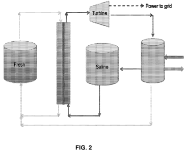
With reference to FIG. 2, the fresh (dilute working fluid) solution and saline
(concentrated draw solution) storage tanks are shown, these achieving the
storage of chemical
potential energy in the difference in salinity between them. The turbine-
generator may convert
the increase in volume of the pressurized draw solution into electrical energy
by depressurizing
the dilute draw stream. Not shown are a pressure exchanger and a booster pump
which may
13
CA 02745702 2011-06-02
WO 2010/065791 PCT/US2009/066658
transfer hydraulic pressure from the dilute draw stream to the concentrated
draw stream to
maintain a constant pressure, or the desired range of dynamic pressure, in the
draw solution
pressurized section. The rightmost tank represents a distillation column used
for the separation of
the dilute draw solution into concentrated and dilute streams, and the arrows
to the right of the
column indicate the introduction and rejection of heat (rejection at lower
temperature). A third
tank, not shown, may be used to hold the diluted draw solution (combined fresh
and saline
solutions), for any period of time before this solution is separated into the
fresh and saline
solutions described above via thermal (i.e. using waste heat) or electric
processes.
In accordance with one or more embodiments, salinity differences in a closed
cycle
reverse osmosis-pressure retarded osmosis (RO-PRO) system may be used to store
electrical
power as a chemical potential difference in two solutions, as the difference
in concentration and
osmotic pressure between them. In this embodiment, electrical energy may be
used to pressurize
a saline stream such that when passed along the surface of a semi-permeable
membrane, the
concentration of this stream occurs, and dilute water is produced on the
permeate side. The
concentrated solution and dilute solution may be stored in separate tanks, and
by this means, the
electrical energy may be transformed into potential energy in the difference
in osmotic pressure
between the two solutions. The energy capacity of the system may be dictated
by the volumes of
the two solutions and the difference in osmotic pressure between them. This
potential energy
may be stored over long periods without degradation and the storage medium is
inherently safe.
The power output may be generally related to the osmotic pressure difference
between the two
solutions, the hydraulic pressure on the draw solution, and the membrane area
used.
When electrical energy is desired, the two solutions may be used in a closed
cycle PRO
process to generate electrical power, by inducing flux of water from the
dilute solution, across
the semi-permeable membrane, into the pressurized draw solution. This increase
in volume of
the draw solution may be depressurized in a turbine, creating electrical power
using a generator.
In some embodiments, the efficiency of this process may be nearly identical to
the efficiency of
pumping water up an elevation gradient (pumped hydro), in that the
pressurization pump and
turbine efficiencies are similar. Inefficiencies may be due to any pressure
exchanger (95-98%
efficient) implemented and related booster pump used to maintain the pressure
of the draw
solution by hydraulic pressure transfer between the exiting dilute draw
solution and the incoming
concentrated draw solution, as well as by frictional pressure losses in the
piping, heat transfer,
14
CA 02745702 2011-06-02
WO 2010/065791 PCT/US2009/066658
and membrane systems. The overall efficiency of energy storage is expected to
be greater than
75%. In this embodiment, it may be desirable to use a thermal stripping and
absorption system
as a solute blow down to maintain low concentrations of solutes in the dilute
stream, as there
may be a tendency for these to cross into the permeate during the RO step. In
some
embodiments, a periodic blow down of the dilute solution could be carried out,
with a recharge
of dilute water, to maintain a low concentration of solutes in the dilute
stream.
In an alternate embodiment, nanofiltration (NF) membranes rather than RO
membranes
might be used for the energy storage combined with PRO for power production.
In some
embodiments using divalent salts as the draw solutes, NF membranes may perform
the same
functions but provide reduced resistance to water flux.
In other embodiments, other solutes may be used, such that they may be
periodically
reduced in concentration from the dilute solution (permeate of RO step), by
any separation
means that is effective in their removal and does not have too large an
adverse impact on the
overall efficiency. An example of such a secondary separation step would be an
ion exchange
resin system on the dilute stream, recharged with the concentrated draw
solution or with acid
and/or base. An example of such a solute could be a variety of divalent salts.
Other draw solutes
could be used in the electrical storage variant if they create high osmotic
pressure, and are well
rejected by the RO or NF and PRO membranes. In an alternate embodiment,
divalent salts could
be used in the electrical variant with high rejection RO and PRO membranes, as
their passage
into the permeate would be very small. Alternately, solutes with near complete
rejection by the
membrane could be employed, such as low molecular weight charged organic
molecules or
trivalent salts. In an alternate embodiment, a solute which undergoes a
precipitation with a
change in temperature could be used as the draw solute, which may include
organic and/or
inorganic solutes. The separation of these solutes in the energy storage phase
could be carried
out wholly or in part by a thermal manipulation of the dilute draw solution,
with or without a
membrane separation step.
In some embodiments, the draw solute used may be sodium chloride or any other
salt or
osmotic agent, but one of two conditions should be met for the use of such
conventional solutes:
the membrane should be nearly 100% effective in rejecting salt passage (e.g.
carbon nanotubes
or aquaporin like membranes), or the dilute solution should be periodically
blown down and
replaced with fresh, very low salinity water, or subjected to a secondary
separation step to
CA 02745702 2011-06-02
WO 2010/065791 PCT/US2009/066658
maintain the low concentration of solutes in the dilute working fluid. This is
due to the
accumulation of salts that would occur in the dilute draw solution over
repeated cycles of energy
storage and delivery, as draw solutes passed into the permeate of the RO
operation phase of the
plant, which would cause undesirable internal concentration polarization in
the PRO system or
reduce the effectiveness of a reverse electrodialysis (RED) or other power
generating system. In
this way, the dilute working fluid solution may be maintained at low salinity
over an arbitrary
number of cycles.
In other embodiments, the draw solute used may be an ammonia - carbon dioxide
solute,
such as may be derived from an ammonia-carbon dioxide thermolytic salt draw
solution osmotic
agent. Such draw solutes may result from a forward osmosis desalination
process or an osmotic
heat engine process including but not limited to those described in
W02008/060435, U.S. Patent
No. 6,391,205 and U.S. Patent Publication No. US2005/0145568, each being
incorporated above
by reference in its entirety for all purposes. In this configuration, small
quantities of draw solute
may be expected to pass into the dilute solution during the RO phase of
operation, but these may
be periodically or continuously removed and recycled to the concentrated
solution by the use of
thermal separation of the solutes from the dilute solution by the addition of
heat, by for example,
the use of a distillation column as is described in the forward osmosis
desalination and osmotic
heat engine processes referenced above, as well as that described in PCT
Application Publication
No. W02007/146094 which is hereby incorporated herein by reference in its
entirety for all
purposes. As such, the dilute working fluid solution may be maintained at low
salinity over an
arbitrary number of cycles.
In accordance with one or more embodiments, it may be important to maintain
the low
salinity of the dilute solution, to prevent internal concentration
polarization in the membrane
structure. In accordance with one or more embodiments, salts other than the
ammonia - carbon
dioxide draw solutes may be used. This may be particularly desirable if the
separation and
recombination means involve high rejection. For example, if a membrane that
rejected nearly
100% of all salts is used, then any salt, including NaCl and MgCI could be
used.
With reference to FIG. 3, the fresh solution and saline solution tanks may
hold the dilute
working fluid and concentrated draw solution, respectively. The pump may be
used to cause
pressurization of the concentrated solution, leading to the permeation of the
dilute solution
through the semi-permeable membrane into the dilute solution tank, designated
"fresh". This
16
CA 02745702 2011-06-02
WO 2010/065791 PCT/US2009/066658
may have the effect of concentrating the saline solution. By the storage of
arbitrary volumes of
fresh and saline solutions of differing salinity (osmotic pressures), the
difference in chemical
potential of these solutions may be used as a stable, inherently safe energy
storage means. A
third tank, not shown, may be used to hold the diluted draw solution (combined
fresh and saline
solutions), for any period of time before this solution is separated into the
fresh and saline
solutions described above by the use of electrical power to induce reverse
osmotic flow through
the membrane. This system may have two modes of operation: RO to store power
as differences
in salinity between two solutions, and PRO to transform this difference in
salinity into electrical
power. For PRO operation, the pressure exchanger shown may be used with a
booster pump (not
shown) to maintain the pressure on the concentrated draw solution by
transferring hydraulic
pressure from the exiting dilute draw solution to the incoming concentrated
draw solution, to
transform the salinity difference between the two solutions into electrical
power. This power
production may be achieved by allowing the pressurized, expanding volume of
dilute draw
solution to depressurize in the turbine, for example, as described above with
respect to separation
and pressure retarded osmosis processes. The leftmost vessel is a small
distillation column which
may be used to periodically or continuously remove solutes from the dilute
solution, by means of
heat stripping of the solutes, to maintain the low salinity of the solution.
Alternately, a dilute
solution blow down and recharge cycle may be used to maintain low salinity in
this solution.
Additional embodiments that may be employed include the use of
electrodialysis, ion
exchange, capacitive deionization, pervaporation, membrane separation or other
separation
means in lieu of the use of RO or the distillation column, for the separation
of the dilute solution
into concentrated and dilute streams. RED or other electrochemical techniques
for generating
electricity from salinity differences may be used in lieu of the pressure
retarded osmosis step.
The technology disclosed herein is broadly directed to various approaches of
using heat or power
to separate, and the later or simultaneous recombination of these solutions to
produce power.
In some embodiments, one or more disclosed osmotic storage devices and methods
may
be implemented to improve or increase an overall efficiency of an electrical
plant. For example,
disclosed systems and methods may be used to supplement conventional, base
load electrical
generation from sources such as coal and natural gas and nuclear. Existing
plants may therefore
be retrofitted in accordance with one or more embodiments for enhanced
efficiency, reliability
and storage.
17
CA 02745702 2011-06-02
WO 2010/065791 PCT/US2009/066658
In some nonlimiting embodiments, water power potential between a fresh
solution and a
concentrated draw solution may be about 300 bar or nearly 10,000 feet of
hydraulic head. In at
least some nonlimiting embodiments, overall system efficiency may be in the
range of 55% to
85%. In at least one embodiment, the efficiency obtainable is at least about
75%.
In accordance with one or more embodiments, a water product may be generated
by the
disclosed systems and methods. A water product may have one or more
characteristics or
qualities rendering it useful or desirable in various applications. A water
product may be treated
water. In at least one embodiment, a water product may be desalinated water.
Thus, in addition
to stored energy, i.e. electricity, water may be provided to a point of use or
customer depending
upon demand. In some non-limiting embodiments, for example, a water product
may be
provided for use in industrial, irrigation or potable applications. The water
product may be
produced through a separation process described herein.
In some embodiments, osmotic storage devices and methods may be charged by
waste
heat as disclosed herein. Energy storage efficiency, as a percentage of input
energy returned,
may therefore be rendered substantially irrelevant in certain aspects. In at
least one embodiment,
osmotic storage devices and methods may be charged using only waste heat. Heat
may come
from conventional thermal power generation sources. In some embodiments, coal,
natural gas,
nuclear and oil power generation sources may provide the waste heat. For
example, power
generation or combined heat and power (CHP) systems involving boilers, gas
turbines and
reciprocating engines may provide waste heat. Industrial or commercial boilers
for steam and
heat generation may provide waste heat. Heat may also come from unconventional
sources such
as solar thermal power generation, geothermal power generation, district heat
and cooling water,
or produced fluids such as from oil and natural gas extraction, fracturing and
enhanced oil
recovery operations. In still other embodiments, heat may be cogenerated on
site such as
through distributed generation combined with osmotic storage or combined
utility scale power
generation and osmotic storage.
In other embodiments, an electrical version of the devices and methods may be
implemented as described above. Generated electricity may be supplied to
devices of such
embodiments to power one or more unit operations thereof. In such embodiments,
energy
storage efficiency may be a significant consideration. In at least one
embodiment, hybrid
systems and methods may rely upon waste heat as well as electricity.
18
CA 02745702 2011-06-02
WO 2010/065791 PCT/US2009/066658
Osmotic grid storage systems in accordance with one or more embodiments may be
used
for thermal power generation. An osmotic grid storage device may be used in
conjunction with
any thermal power generation source to capture and convert reject heat to
stored, on demand
power. The osmotic grid storage systems disclosed can charge up to 24 hours
per day with the
reject heat from the power plant and supply large amount of hydro power at
peak times during
the day when power is need and most expensive. This may increase the overall
efficiency of the
plant, reduce the carbon footprint and also provide on-demand functionality
for a portion of the
total power output that is not a capability that exists today.
Osmotic grid storage systems in accordance with one or more embodiments may
also be
used for solar thermal storage or geothermal storage. Geothermal heat
extracted from the ground
either from a conventional hydrothermal source or from an enhanced geothermal
system (EGS)
source can be converted to stored energy. This may increase the overall
efficiency of a
geothermal power plant and also adds a storage component. If stored power is
more valuable,
more heat or higher temperature heat can be sent to the osmotic grid storage
system for increased
storage rather than to the binary plant for immediate power generation. In
some embodiments,
an osmotic grid storage system can be combined with an organic rankine cycle
(ORC) to provide
the most efficient use of heat down to temperatures as low as 40 C.
In accordance with one or more embodiments, disclosed osmotic storage systems
may be
used for small scale storage. An osmotic grid storage system can be scaled
down to small sizes,
for example, in the 1-20MW range for distributed, industrial or consumer power
storage
applications. An osmotic grid storage system can be integrated with small
scale reciprocating
engines or generators for example to capture the reject heat and provide on-
demand electrical
power. Small scale osmotic grid storage systems can also utilize heat from
industrial appliances
such as furnaces, hot water heaters and small boilers. Even smaller scale
osmotic grid storage
systems can also utilize simple solar collectors such as those found on
rooftops to provide on-
demand power.
In accordance with one or more embodiments, osmotic grid storage systems may
be used
for nuclear storage. An osmotic grid storage system can be coupled with
nuclear energy to store
large amounts of on-demand power. Nuclear energy is an extremely efficient
method of
generating heat with no carbon impact. This heat can be used directly or
indirectly as in the form
of wasted heat to power an osmotic grid storage system. This may increase the
overall efficiency
19
CA 02745702 2011-06-02
WO 2010/065791 PCT/US2009/066658
of a nuclear plant and provides a storage mechanism that does not exist today
in nuclear
facilities.
In accordance with one or more embodiments, osmotic grid storage systems may
be used
for district heating and cooling. An osmotic grid storage system can be
coupled with hot water
produced from a district heating and cooling system. When power is generated,
steam may be
recovered through a condenser where heat is rejected. In some instances, such
as co-generation
systems, that heat is then used for district heating and cooling. Often heat
is in the form of hot
water that is piped through the streets at a temperature range of 40-50 C.
This heat can be used
to power an osmotic grid storage system to provide stored power.
In accordance with one or more embodiments, osmotic grid storage systems may
be used
with an osmotic heat pump. An osmotic grid storage system can be coupled with
a geothermal
heat pump to provide the necessary heat to recover the draw solution. In this
instance, the
distillation columns can be eliminated and instead replaced with an
underground heat pump that
provides the draw solute separation. In this way, small scale osmotic grid
storage systems can be
deployed anywhere there are reasonable subsurface temperatures providing
residential,
commercial and distributed energy storage systems.
In accordance with one or more embodiments, grid storage systems may use an
electrical
energy in, electrical energy out approach. In one example, RO may be used to
concentrate a
diluted divalent salt solution into a concentrated solution and substantially
dilute working fluid.
These solutions can be stored indefinitely to store the electricity as
chemical potential. When
power is needed, PRO may be used to recombine these solutions to create
electrical power. In
some embodiments, a polishing method may be used to prevent the build up of
solutes in the
working fluid, such as inclusion of ion exchange or other separation methods.
In this way, the
osmotic grid storage system may prevent solute build-up. Weak acid and base
anion and cation
exchange resins, for example, may also be used with multivalent salt
solutions. Periodic blow
down may also be implemented as disclosed herein.
In accordance with one or more embodiments, devices, systems and methods may
generally involve a controller for adjusting or regulating at least one
operating parameter of the
device or a component of the system, such as, but not limited to, actuating
valves and pumps, as
well as adjusting a property or characteristic of one or more fluid flow
streams. A controller may
be in electronic communication with at least one sensor configured to detect
at least one
CA 02745702 2011-06-02
WO 2010/065791 PCT/US2009/066658
operational parameter of the system, such as a concentration, flow rate, pH
level or temperature.
The controller may be generally configured to generate a control signal to
adjust one or more
operational parameters in response to a signal generated by a sensor. For
example, the controller
can be configured to receive a representation of a condition, property, or
state of any stream,
component or subsystem of an osmotic separation device or grid storage system.
The controller
typically includes an algorithm that facilitates generation of at least one
output signal which is
typically based on one or more of any of the representation and a target or
desired value such as
a set point. In accordance with one or more particular aspects, the controller
can be configured
to receive a representation of any measured property, and generate a control,
drive or output
signal to any of the system components, to reduce any deviation of the
measured property from a
target value.
In accordance with one or more embodiments, process control systems and
methods may
monitor various concentration levels, such as may be based on detected
parameters including pH
and conductivity. Process stream flow rates and tank levels may also be
controlled.
Temperature and pressure may be monitored. Membrane leaks may be detected
using ion
selective probes, pH meters, tank levels and stream flow rates. Leaks may also
be detected by
pressurizing a draw solution side of a membrane with gas and using ultrasonic
detectors and/or
visual observation of leaks at a feedwater side. Other operational parameters
and maintenance
issues may be monitored. Various process efficiencies may be monitored, such
as by measuring
product water flow rate and quality, heat flow, electrical energy consumption
and energy output.
Cleaning protocols for fouling mitigation may be controlled such as by
measuring flux decline as
determined by flow rates of feed and draw solutions at specific points in a
membrane system. A
sensor on a brine stream may indicate when treatment is needed, such as with
distillation, ion
exchange, breakpoint chlorination or like protocols. This may be done with pH,
ion selective
probes, Fourier transform infrared (FTIR) spectroscopy or other means of
sensing draw solute
concentrations. A draw solution condition may be monitored and tracked for
makeup addition
and/or replacement of solutes. Likewise, product water quality may be
monitored by
conventional means or with a probe such as an ammonium or ammonia probe. FTIR
may be
implemented to detect species present providing information which may be
useful, for example,
to ensure proper plant operation, and for identifying behavior such as
membrane ion exchange
effects.
21
CA 02745702 2011-06-02
WO 2010/065791 PCT/US2009/066658
In accordance with one or more embodiments, systems and methods may be
integrated
with an electric grid to meet energy requirements. Systems and methods may be
integrated with
base load energy to provide standby power, be used to level energy output and
add reliability to
powered processes. In some embodiments, a power demand may be monitored. A
controller
associated with disclosed systems may receive a signal indicative of a power
demand. In some
embodiments, an osmotic power generation process, such as a pressure retarded
osmosis process
discussed herein, may be initiated or brought online in response to detecting
a power demand.
Likewise, power generation may be terminated in the absence of a power demand.
Separation
processes for storage of potential energy in the form of a concentration
gradient between a
concentrated solution and a substantially deionized solution may be performed
when energy is
not being produced. In other embodiments, separation processes may be
performed concurrently
with energy generation.
The function and advantages of these and other embodiments will be more fully
understood from the following non-limiting example. The example is intended to
be illustrative
in nature and is not to be considered as limiting the scope of the embodiments
discussed herein.
EXAMPLE 1
Various storage technologies, including the disclosed osmotic systems and
methods, were
modeled based on comparative size and operational parameters and evaluated in
terms of
efficiency and capital cost. Table 1, below, summarizes the results regarding
efficiency.
Table 1.
Storage technology Efficiency
Pumhcd storagc 7O-854
Flow batteries 75-85%
Na-S hattcrics KS ~)0~4
. . . . . . . . . . . . . . . . . . . . . . . . . . . . . . . . . . . . . . .
. . . . . . . . . . . . . . .. . . . . . . . . . . . . . . . . . . . . . . . .
. . . . . . . . . . . . . . . . . . . . . . . . .
Li-ion hattcrics 90 95`/
("on pi'csscd air 7O K0(4
Fly whccls 9O 95'/,
Osmotic systems 75-85 %
...............................................................................
..........................
22
CA 02745702 2011-06-02
WO 2010/065791 PCT/US2009/066658
As indicated, the efficiency of the disclosed osmotic systems and methods is
competitive,
particularly in view of the fact that waste heat can be used.
The results of the evaluation also indicated that osmotic systems and methods
disclosed
herein are associated with a lower capital cost per kilowatt relative to the
conventional storage
technologies. For example, the pumped storage systems were two to four times
more expensive.
Flow batteries were up to three times more expensive. Sodium-sulfur batteries
were up to two
and one-half times more expensive. Lithium-ion batteries were up to four times
more expensive.
Fly wheels were about four times more expensive.
The evaluation illustrated the desirability of disclosed osmotic systems and
methods for
grid storage in terms of both efficiency and capital cost.
EXAMPLE 2
A cost analysis was performed on an osmotic grid storage system modeled in
accordance
with one or more embodiments disclosed herein. The system specifications upon
which the
modeling was based included a total energy storage capacity of 600 MWH,
delivery power of
100MW, a 12 hour delivery time, 150 ATM pressure and a 1 GW coal plant used to
supply waste
heat. The analysis resulted in an estimated cost per kilowatt hour of $0.08
indicating the
viability of osmotic grid storage as an energy solution.
EXAMPLE 3
An analysis was performed to model cost per kilowatt hour as a function of
storage
capacity for an osmotic grid storage system in accordance with various
embodiments. Results
presented in Table 2, below, indicate a drop-off of cost per kilowatt hour
with increased MWH
storage capacity. Tripling the storage more than halved the cost. An estimated
$0.098/KWH at
30MWH storage capacity is attractive compared to conventional grid storage
options.
Table 2.
INN
Delivery Power 5MW 5MW 5MW
Delivery Hours 2 hours 4 hours 6 hours
MWH Storage 1OMWH 2OMWH 30MWH
$/KWH $0.275 $0.144 $0.098
23
CA 02745702 2011-06-02
WO 2010/065791 PCT/US2009/066658
EXAMPLE 4
Solar thermal is one of the most promising emerging forms of clean electricity
with the
ability to provide large amounts of future power demand with zero emissions.
However, solar
thermal technologies require some form of energy storage so they can deliver
power during the
night when there is no sunlight. Without energy storage, solar thermal
electricity is limited and
discounted in the market, as it cannot be available 24 hr/day reliably. Solar
thermal plants
require roughly 16 hours of storage to alleviate this problem - this
immediately eliminates many
grid storage options (like batteries) that are uneconomical at this scale. The
disclosed osmotic
grid storage can be constructed anywhere solar thermal plants exist and can
store many hours of
power at multi-megawatt or multi-gigawatt scales. In addition, because solar
thermal is a
`thermal' generation process, there is significant waste heat available (below
150 C) that does
not contribute to power generation. During the day when the plant is producing
electricity at
capacity, the plant can also be utilizing waste heat for storage without
affecting the overall heat
rate (output) of the plant. At night, the osmotic battery can be turned on to
discharge power and
maintain capacity. This level of added reliability can significantly enhance
the profitability of a
solar thermal power plant.
EXAMPLE 5
Osmotic grid storage systems and methods may be combined with a gas turbine
combined cycle (GTCC) in accordance with one or more embodiments. Preliminary
modeling,
as presented in the schematic of FIG. 4, suggests a storage capacity in excess
of 530 MW.
EXAMPLE 6
Osmotic grid storage systems and methods may be combined with a diesel
generator in
accordance with one or more embodiments. As presented in the schematic of FIG.
5A, osmotic
storage may be integrated with a 10MW diesel generator. As presented in the
schematic of FIG.
513, osmotic energy storage may be integrated with a diesel generator as well
as a heat recovery
steam generator (HRSG) to recover heat from a hot gas stream.
24
CA 02745702 2011-06-02
WO 2010/065791 PCT/US2009/066658
EXAMPLE 7
Osmotic grid storage systems and methods may be combined with power plant
cooling
processes in accordance with one or more embodiments. A typical power plant
cooling process
is presented in FIG. 6A. FIG. 6B reflects the ease with which osmotic storage
may be integrated.
Having now described some illustrative embodiments of the invention, it should
be
apparent to those skilled in the art that the foregoing is merely illustrative
and not limiting,
having been presented by way of example only. Numerous modifications and other
embodiments are within the scope of one of ordinary skill in the art and are
contemplated as
falling within the scope of the invention. In particular, although many of the
examples presented
herein involve specific combinations of method acts or system elements, it
should be understood
that those acts and those elements may be combined in other ways to accomplish
the same
objectives.
It is to be appreciated that embodiments of the devices, systems and methods
discussed
herein are not limited in application to the details of construction and the
arrangement of
components set forth in the following description or illustrated in the
accompanying drawings.
The devices, systems and methods are capable of implementation in other
embodiments and of
being practiced or of being carried out in various ways. Examples of specific
implementations
are provided herein for illustrative purposes only and are not intended to be
limiting. In
particular, acts, elements and features discussed in connection with any one
or more
embodiments are not intended to be excluded from a similar role in any other
embodiments.
Those skilled in the art should appreciate that the parameters and
configurations
described herein are exemplary and that actual parameters and/or
configurations will depend on
the specific application in which the systems and techniques of the invention
are used. Those
skilled in the art should also recognize or be able to ascertain, using no
more than routine
experimentation, equivalents to the specific embodiments of the invention. It
is therefore to be
understood that the embodiments described herein are presented by way of
example only and
that, within the scope of any appended claims and equivalents thereto; the
invention may be
practiced otherwise than as specifically described.
Moreover, it should also be appreciated that the invention is directed to each
feature,
system, subsystem, or technique described herein and any combination of two or
more features,
CA 02745702 2011-06-02
WO 2010/065791 PCT/US2009/066658
systems, subsystems, or techniques described herein and any combination of two
or more
features, systems, subsystems, and/or methods, if such features, systems,
subsystems, and
techniques are not mutually inconsistent, is considered to be within the scope
of the invention as
embodied in any claims. Further, acts, elements, and features discussed only
in connection with
one embodiment are not intended to be excluded from a similar role in other
embodiments.
The phraseology and terminology used herein is for the purpose of description
and should
not be regarded as limiting. As used herein, the term "plurality" refers to
two or more items or
components. The terms "comprising," "including," "carrying," "having,"
"containing," and
"involving," whether in the written description or the claims and the like,
are open-ended terms,
i.e., to mean "including but not limited to." Thus, the use of such terms is
meant to encompass
the items listed thereafter, and equivalents thereof, as well as additional
items. Only the
transitional phrases "consisting of' and "consisting essentially of," are
closed or semi-closed
transitional phrases, respectively, with respect to any claims. Use of ordinal
terms such as
"first," "second," "third," and the like in the claims to modify a claim
element does not by itself
connote any priority, precedence, or order of one claim element over another
or the temporal
order in which acts of a method are performed, but are used merely as labels
to distinguish one
claim element having a certain name from another element having a same name
(but for use of
the ordinal term) to distinguish claim elements.
26