Note: Descriptions are shown in the official language in which they were submitted.
CA 02745792 2011-07-08
-I-
ELEVATOR CAR DOOR INTERLOCK
100011
BACKGROUND
[0002] Some exemplary elevator systems comprise elevator cars traveling
through a
hoisiway. In such systems, the elevator cars comprise doors and the
hoistway comprises doors at various landing zones. In operation, while
moving through the hoistway, the elevator car doors remain closed until
stopping at a landing zone where the elevator car doors and the hoistway
doors can align and open, thus allowing passengers to enter and exit. If the
elevator system malfunctions and stops between floors, a passenger in the
elevator car can attempt to open the elevator car door. In another situation,
the elevator system could malfimction and unlock the elevator car door as the
elevator car is moving, allowing a passenger to open the elevator car door.
Each of these situations risks injury to the passenger. Thus, in some
instances it is desirable that the elevator car door remain closed when
moving between floors and stay closed if the elevator slops outside a landing
zone so that passengers cannot open the elevator car door.
CA 02745792 2011-07-08
-2-
[0003] While a variety of elevator car door locking systems have been made and
used, it is believed that no one prior to the inventors has made or used an
invention as described herein.
BRIEF DESCRIPTION OF THE DRAWINGS
[0004] While the specification concludes with claims which particularly point
out
and distinctly claim the invention, it is believed the present invention will
be
better understood from the following description of certain examples taken in
conjunction with the accompanying drawings. In the drawings like reference
numerals identify the same elements.
[0005] FIG. I depicts a perspective view of an exemplary elevator car
incorporating
an exemplary car door interlock.
[0006] FIG, 2 depicts an enlarged perspective view of the car door interlock
of FIG.
I .
[0007] FIG. 3 depicts a partial front view of the elevator car of FIG. 1.
[0008] FIG, 4 depicts a partial perspective view of the car door interlock of
FIG. 1,
showing an exemplary unlock zone assembly,
[0009] FIG. 5 depicts a partial perspective view of the car door interlock of
FIG. 1,
showing the elevator car door closed and the car door interlock in a locked
position.
[0010] FIG, 6 depicts an enlarged perspective view of a portion of the car
door
interlock of FIG. 5.
[0011] FIG. 7 depicts a partial perspective view of the car door interlock of
FIG. 1,
showing the elevator car door open and the car door interlock in an unlocked
position.
[0012] FIG. 8 depicts a front view of the interior of an exemplary interlock
assembly of the car door interlock of FIG. 1, shown in the locked position.
CA 02745792 2011-07-08
-3-
[00131 FIG. 9 depicts a front view of the interior of the interlock assembly
of the car
door interlock of FIG. 1, shown in the unlocked position.
[00141 FIG. 10 depicts a front view of the interior of the car door interlock
in FIG.
1, showing the interlock assembly and an exemplary control box.
[0015] FIG. I I depicts a partial front view of another exemplary car door
interlock.
[00161 FIG. 12 depicts a perspective view of the car door interlock of FIG.
11,
[00171 FIG. 13 depicts an enlarged perspective view of a portion of the car
door
interlock of FIG. 12.
[0018[ The drawings are not intended to be limiting in any way, and it is
contemplated that different versions may be carried out in other ways,
including those not necessarily depicted in the drawings. The accompanying
drawings illustrate several aspects of the present invention, and with the
description serve to explain the principles of the invention. The present
invention is not limited to the precise arrangements shown.
DETAILED DESCRIPTION
100191 The following description of certain examples of the invention should
not be
used to limit the scope of the present invention. Other examples, features,
aspects, embodiments, and advantages of the invention will become apparent
to those skilled in the art from the following description. As will be
realized,
the invention is capable of other different and obvious aspects, all without
departing from the invention. Accordingly, the drawings and descriptions
should be regarded as illustrative in nature and not restrictive.
[00201 FIG. 1 illustrates an exemplary elevator car (10) incorporating an
exemplary
a car door interlock (12), where elevator car (10) travels within a hoistway
(2). Elevator car (10) comprises car door interlock (12), elevator car door
(14), and door operator (16). 1-loistway (2) has one or more hoistway doors
(not shown) located at various landing zones along hoistway (2). The
landing zones are areas within hoistway (2) where elevator car door (14) can
CA 02745792 2011-07-08
-4-
align with the hoistway door such that elevator car door (14) and the
hoistway door can safety open and close to allow passengers to enter or exit
elevator car (10).
[00211 In the illustrated version, elevator car (10) comprises a single
elevator car
door (14) connected to door operator (16). Door operator (16) is operable to
open and close elevator door (14) by sliding elevator door (14) in first and
second directions using conventional means known to those of ordinary skill
in the art. In other versions, elevator car (10) comprises multiple elevator
car
doors (14). By way of example only, in some versions elevator car (10)
comprises two doors where the doors have a center opening. Still in other
versions elevator car (10) comprises two or more speed doors.
[00221 In the illustrated version, car door interlock (12) is securely
attached to
portions of elevator car (10) near the top of elevator car (10) above elevator
car door (14). In other versions, car door interlock (12) is installed in
other
positions on elevator car (10). By way of example only, in some versions car
door interlock (12) is securely attached to portions of elevator car (10) near
the bottom of elevator car (10) below elevator car door (14). Still in other
versions, car door interlock (12) can be positioned anywhere on elevator car
(10) where car door interlock (12) can contact elevator car door (14), either
directly or through an intervening structure, to lock and unlock elevator car
door (14) as will be discussed further below.
100231 FIGS. 2 and 3 illustrate car door interlock (12), which comprises
interlock
assembly (18), control box (20), and unlock zone assembly (22). In one
version, interlock assembly (18) and control box (20) are mounted to a car
header (64), which may be mounted at the top of elevator car door (14). In
other versions, interlock assembly (18), control box (20), and unlock zone
assembly (22) are attached directly to the top of elevator car door (14)
without the use of car header (64). In other versions, interlock assembly
(18), control box (20), and unlock tone assembly (22) are mounted at
separate locations from each other, or are mounted near each other at a
CA 02745792 2011-07-08
-5-
location other than the top of elevator car door (14), such as, for example,
near the bottom of elevator car door (14), inside elevator car door (14), at a
remote location from elevator car door (14), or at any other suitable location
which will be apparent to those of ordinary skill in the art in view of the
teachings herein,
10024] Interlock assembly (18) and unlock zone assembly (22) are connected
with
control box (20) by wire harness (72) and wire harness (74) respectively.
Control box (20) is connected with car operating panel (70) of elevator car
(10) by wire harness (76). Door operator (16) is connected with car
operating panel (70) by wire harness (78). Car operating panel (70) is
connected with elevator controller (82) by wire harness (80). Thus control
box (20) and door operator (16) are in communication with elevator
controller (82) via car operating panel (70). In some versions, interlock
assembly (18) and unlock zone assembly (22) are in communication with
elevator controller (82) via control box (20) and car operating panel (70). In
other versions any suitable communication connection scheme between the
components can be used. By way of example only, in some versions
redundant communication connections are used, e.g., where interlock
assembly (18) and unlock zone assembly (20) are connected with car
operating panel (70) directly in addition to indirectly via control box (20).
Still in other versions various components in addition to car operating panel
(70) can be directly connected to elevator controller (82).
[00251 Wire harnesses (72, 74, 76, 78, 80) allow for communications to be
transmitted and received between components. In other versions, such
communications between components can be accomplished by other means.
By way of example only, a wireless communication system can be used.
Still other communication means will be apparent to those of ordinary skill
in the art based on the teachings herein.
[0026] In the present example, car operating panel (70) is accessible to a
passenger
and is operable to receive a variety of instructions from a passenger. Still
in
CA 02745792 2011-07-08
-6-
other versions, car operating panel (70) is shielded from access by a
passenger. In the present example, the instructions from the passenger are
relayed to other components. For example, in some instances car operating
panel (70) sends instructions to elevator controller (82) specifying a
particular floor to which the passenger wishes to travel. In some instances,
car operating panel (70) sends instructions to door operator (16) requesting
that elevator car door (14) remain open. In some instances, car operating
panel (70) sends instructions to door operator (16) requesting that elevator
car door (14) be closed. In the present example, car operating panel (70) is
configured to interface with control box (20) of car door interlock (18)
regarding actions requested by the passenger as these actions relate to
control
of elevator car door (14). For instance, where a passenger request would
require elevator car door (14) to be locked or unlocked, control box (20)
determines if certain conditions are met such that the passenger's request can
be accommodated. If such conditions are met, then control box (20)
communicates with interlock assembly (18) to lock or unlock elevator car
door (14). In some versions, the information received at car operating panel
(70) regarding a passenger request that impacts the operation of elevator car
door (14) is relayed directly to elevator controller (82), and elevator
controller (82) determines if certain conditions are met such that the
passenger's request can be accommodated. In such versions, if such
conditions are met, then elevator controller (82) communicates with control
box (20), which further communicates with interlock assembly (18) to lock
or unlock elevator car door (14). By way of example only, in some versions
the conditions considered for locking and unlocking elevator car door (14)
comprise: first, whether or not elevator car (10) is moving, and second,
whether or not elevator car is located at a designated landing zone. The
conditions would be considered met in this example when the elevator car
(10) was not moving and was located at a designated landing zone.
(00271 PIG. 4 illustrates unlock zone assembly (22) of car door interlock
(12).
Unlock zone assembly (22) is mounted on elevator car (10). In some
CA 02745792 2011-07-08
-7-
versions, unlock zone assembly is configured to be mounted on a bracket of
elevator car (10) that is attached to a header of door operator (16), Unlock
zone assembly (22) reads an element within hoistway (2) as elevator car (10)
travels within hoistway (2). In some versions the element is located on a
bracket attached to a header of each floor in hoistway (2). Unlock zone
assembly (22) is configured to detect the position of elevator car (10) based
at least in part on proximity to the associated element. The detection of this
position information provides information related to whether or not elevator
car (10) is positioned at a designated landing zone. Unlock zone assembly
(22) communicates position information to control box (20).
[00281 In the illustrated version, unlock zone assembly (22) comprises one or
more
landing zone sensors (26). Landing zone sensors (26) are operable to detect
when elevator car (10) is positioned at a designated landing zone within
hoistway (2). In one version, landing zone sensors (26) comprise two Reed
switches, of course other suitable sensors as would be apparent to one of
ordinary skill in the art in view of the teachings herein can be used. In the
illustrated version, one or more landing zone magnets (28) are positioned
within hoistway (2) at or near designated landing zones and landing zone
sensors (26) are capable of detecting landing zone magnets (28). In one
version, landing zone magnets (28) are positioned on a leveling vane such
that when landing zone sensors (26) and landing zone magnets (28) are
aligned, elevator car (10) is positioned properly within a landing zone. Any
suitable number of landing zone sensors (26) and any suitable number of
landing zone magnets (28) can be used. In other versions, detection schemes
other than, or in addition to, magnetic sensors and magnets can be used to
detect landing zones. By way of example only, in some other versions
optical sensors can be used to identify certain markings that can be located
at
the landing zones. Still other detection schemes for identifying landing
zones will be apparent to those of ordinary skill in the art based on the
teachings herein. Once unlock zone assembly (22) establishes that elevator
car (10) is in a landing zone and communicates that elevator car (10) is
CA 02745792 2011-07-08
-8-
located in a landing zone to control box (20), then control box (20)
communicates to interlock assembly (18) indicating that interlock assembly
(18) can unlock elevator car door (14) to allow elevator car door (14) to
open, assuming that other required conditions are met (e.g., elevator car (10)
is not moving). In some versions, one or more programmable interface
controllers (PICs) can be configured to monitor each of landing zone sensors
(26) to ensure proper operation of car door interlock (12).
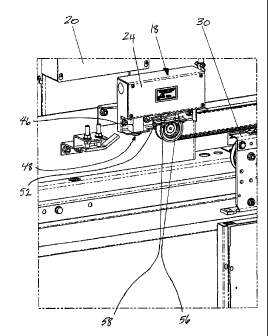
[00291 FIGS. 5-9 illustrate interlock assembly (18). Interlock assembly (18)
comprises assembly housing (24), sensor board (38), solenoid (46), lock pin
(48), gate switch top contact arm (50), gate switch bottom contact arm (52),
door closed sensor (58), and door partially opened sensor (56).
100301 Assembly housing (24) can be constructed of plastic, metal, a metal-
alloy, or
any other suitable material. Assembly housing (24) can be integrally formed
or may be constructed by securing separately formed pieces with glue,
screws, bolts, etc. A portion of assembly housing (24) is removably attached
so as to allow a user to open assembly housing (24) to access components
contained inside, or in the alternative, assembly housing (24) may be
hermetically sealed. Assembly housing (24) may be removably attached to
car header (64) atop elevator car door (14).
[00311 Sensor board (38) is contained inside assembly housing (24) and is
removably attached to assembly housing (24). Sensor board (38) is in
communication with solenoid up sensor (54) and solenoid down sensor (60).
Sensor board is in communication with door closed sensor (58) and door
partially opened sensor (56). Door closed sensor (58) is configured to detect
whether elevator car door (14) is in a closed position, Door partially opened
sensor (56) is configured to detect if elevator car door (14) is opened
approximately 2-4 inches, but may be configured to detect a variable range
or any suitable range of opening positions for elevator car door (14).
Solenoid up sensor (54) is configured to determine if lock pin (48) is in a
retracted position and solenoid down sensor (60) is configured to detect
CA 02745792 2011-07-08
-9-
whether lock pin (48) is in an extended position in relation to solenoid (46).
Each of solenoid up sensor (54), solenoid down sensor (60), door closed
sensor (58), and door partially opened sensor (56) can comprise different
sensors such as, for example, a magnetic or an optical sensor. While in the
present example multiple sensors are used to detect parameters, in some
other versions, a single sensor can be configured to detect multiple
parameters and perform substantially the same functions of solenoid up
sensor (54), solenoid down sensor (60), door closed sensor (58), and door
partially opened sensor (56). As shown in FIG. 10, sensor board (38) is in
communication with a control board (66) contained in control box (20)
which has a visual indicator (44), which may be, for example, an LED to
indicate if each of solenoid up sensor (54), solenoid down sensor (60), door
closed sensor (58), and door partially opened sensor (56) are properly
functioning.
100321 Referring again to FIGS. 5-9, solenoid (46) is positioned generally
inside
assembly housing (24). Solenoid (46) is seated abutting the outer wall of
assembly housing (24) such that a portion of solenoid (46) extends through
assembly housing (24). In the illustrated version, solenoid (46) is pointed in
the direction of elevator car door (14) so as to allow lock pin (48) to engage
car header (64) as shown in FIG, 6. In the present example, car header (64)
is connected with elevator car door (14) and includes opening (65)
configured to receive lock pin (48) when lock pin (48) is extended from
solenoid (46). This engagement between lock pin (48) and opening (65)
locks elevator car door (14) in the closed position. While in the present
example lock pin (48) engages car header (64), in other versions, lock pin
(48) engages other structures connected with elevator car door (l4) to
accomplish locking and unlocking elevator car door (14).
[00331 Solenoid (46) comprises a bi-stable solenoid operable to be energized
to
lift/unlock lock pin (48) or energized to drop/extend lock pin (48). Solenoid
(46) comprises a generally cylindrical or rectangular shape and is in
communication with lock pin (48). Lock pin (48) is positioned within
CA 02745792 2011-07-08
-10-
solenoid (46) or is positioned close enough such that a magnetic field
produced by solenoid (46) is operable to control the movement of lock pin
(48). A magnetic field is produced by a pair of adjustably controllable field
effect transistors (FETs) for coils of each solenoid (46). The two field
effect
transistors per coil of each solenoid (46) may be used to control the magnetic
field produced by solenoid (46). However, any suitable number of FETs
may be used to control the magnetic field produced by solenoid (46).
[00341 Solenoid (46) is configured to actuate lock pin (48) in first and
second
directions thereby moving lock pin (48) to either a retracted position or an
extended position. Lock pin (48) is generally cylindrical in shape, but may
be any suitable shape so as to prevent the opening of elevator car door (14)
once lock pin (48) engages car header (64). In an extended position, lock pin
(48) engages car header (64) to form a lock, thus preventing elevator car
door (14) from opening. In a retracted position, lock pin (48) is configured
to retract into solenoid (46) and no longer engage car header (64), thus
allowing elevator car door (14) to slide from a closed position to an open
position or from an open position to a closed position.
100351 In the illustrated version, gate switch top contact arm (50) is
positioned in
assembly housing (24), Gate switch top contact arm (50) comprises a
cantilevered arm removably attached to assembly housing (24) at a hinge but
any suitable means of attachment may be used. Further, gate switch top
contact arm (50) is in communication with solenoid (46) and is in further
communication with solenoid up sensor (54) and solenoid down sensor (60)
on sensor board (38). Gate switch top contact arm (50) has an open position
as shown in FIG. 9, and a closed position as shown in FIGS. 8 and 10. When
solenoid (46) is actuated such that lock pin (48) is in extended position to
lock elevator car door (14), solenoid (46) pulls cantilevered arm of gate
switch top contact arm (50) downward thereby switching gate switch top
contact arm (50) to closed position as shown in FIG. 8. With gate switch top
contact arm (50) in the closed position, solenoid down sensor (60) detects
gate switch top contact arm (50) signaling that lock pin (48) is extended.
CA 02745792 2011-07-08
-11-
When lock pin (48) moves from an extended position to a retracted position
to unlock elevator car door (14), solenoid (46) actuates cantilevered arm of
gate switch top contact arm (50) upward, which then switches gate switch
top contact arm (50) to an opened position as shown in FIG. 9. With gate
switch top contact arm (50) in the open position, solenoid up sensor (54)
detects gate switch top contact arm (50) signaling that lock pin (48) is
retracted.
[0036] In the illustrated version, gate switch bottom contact arm (52) is
positioned
in assembly housing (24) and positioned below gate switch top contact arm
(50). Gate switch bottom contact arm (52) is configured to have an open
position as shown in FIG. 9, and a closed position as shown in FIGS. 8 and
10. Gate switch bottom contact arm (52) comprises a cantilevered arm
removably attached to assembly housing (24) at a hinge, but any suitable
means of connection may be used. Gate switch bottom contact arm (52) will
be described in greater detail below when discussing interlock roller (32).
[0037] In the illustrated version, door closed sensor (58) and door partially
opened
sensor (56) comprise two magnetic sensors, but any suitable number, type, or
configuration of sensors may be used. Door closed sensor (58) and door
partially opened sensor (56) are positioned parallel to the path of movement
of elevator car door (14) such that door closed sensor (58) and door partially
opened sensor (56), in conjunction, are able to determine whether elevator
car door (14) is fully closed or partially opened by detecting door position
magnets (36), which are located on car header (64) and move with elevator
car door (14) as it opens and closes. For instance, if elevator car door (14)
is
fully closed, then door closed sensor (58) will be triggered; if elevator car
door (14) is partially opened, then only door partially opened sensor (56)
will
be triggered or neither door closed sensor (58) nor door partially opened
sensor (56) will be triggered. Once door closed sensor (58) detects that
elevator car door (14) is closed, door closed sensor (58) communicates to
solenoid (46) to extend lock pin (48), thus locking elevator car door (14). In
one version, in the event that either door closed sensor (58) or door
partially
CA 02745792 2011-07-08
-12-
closed sensor (56) malfunctions, elevator car (10) is signaled to advance to
the next landing zone and halt.
100381 Referring to FIGS. 5 and 6, interlock roller (32) is attached to car
header (64)
by a bracket. Since car header (64) moves with elevator door (14) as it opens
and closes, interlock roller (32) also move with elevator door (14). Interlock
roller (32) is arranged such that when it moves with elevator door (14), it is
positioned underneath gate switch bottom contact arm (52). As mentioned
above, door position magnets (36) are also attached to car header (64) and
positioned such that door position magnets (36) can slidably pass underneath
door closed sensor (58) and door partially opened sensor (56) to actuate door
closed sensor (58) and door partially opened sensor (56). Car header (64) is
in communication with hanger (30), which enables car header (64) to move
back and forth with elevator car door (14) as elevator car door (14) opens
and closes.
[00391 Interlock roller (32) and gate switch bottom contact arm (52) are
positioned
such that interlock roller (32) exerts an upward force on gate switch bottom
contact arm (52) as elevator car door (14) moves from an open to a closed
position. When elevator car door (14) is fully closed, the upward force of
interlock roller (32) on gate switch bottom contact arm (52) actuates the
cantilevered gate switch bottom contact arm (52) to shift it upward to a
closed position. When elevator car door (14) is partially open, the upward
force of interlock roller (32) on gate switch bottom contact arm (52) actuates
gate switch bottom contact arm (52) upward part way to a partially opened
position. When elevator car door (14) opens such that neither door closed
sensor (58) nor door partially opened sensor (56) are triggered, interlock
roller (32) no longer exerts an upward force on gate switch bottom contact
arm (52) such that gate switch bottom contact arm (52) moves to an open
position. In the present example, gate switch contact arm (52) includes
downward extending fin (53) that contacts interlock roller (32) when elevator
car door (14) is sufficiently open such that neither door closed sensor (58)
nor door partially opened sensor (56) detect door position magnets (36).
CA 02745792 2011-07-08
-13-
When interlock roller (32) contacts fin (53), gate switch contact arm (52)
pivots upward at the fin (53) side and downward at the opposite side thus
moving gate switch contact arm (52) to the open position. While the present
example shows fin (53) on gate switch contact arm (52), fin (53) is not
required and in other versions gate contact arm (52) is biased to the open
position such that without upward force of interlock roller (32) gate switch
contact arm (52) will assume an open position. Thus, depending on whether
elevator car door (14) is closed, partially open, or open, gate switch bottom
contact arm (52) will be actuated differently.
100401 In the illustrated version, gate switch top contact arm (50) and gate
switch
bottom contact arm (52) are in communication through gate switch (67),
which comprises first contact unit (68) and a second contact unit (69). When
gate switch top contact arm (50) and gate switch bottom contact arm (52) are
both in a closed position, as shown in FIGS. 8 and 10, gate switch (67) is
closed with first contact unit (68) and second contact unit (69) contacting
gate switch bottom contact arm (52). When gate switch top contact arm (50)
and gate switch bottom contact arm (52) are both in an open position, then
gate switch (67) is open without first contact unit (68) and second contact
unit (69) contacting gate switch bottom contact arm (52). Whether gate
switch (67) is in open position or closed position is then communicated to
elevator controller (82), either directly or via control box (20) by
communication from sensor board (38) to control board (66). In the present
example, gate switch (67) being open means that elevator car door (14) is
unlocked or not fully closed, thus elevator car (10) will not move. But if
gate
switch (67) is closed, that means that elevator car door is locked and filly
closed, thus elevator car (10) is permitted to move.
[00411 FIG. 10 illustrates a front internal view of interlock assembly (18)
along with
control box (20). Control box (20) comprises control board (66),
communications unit (90), at least one programmable interface controller
(PIC) (96), battery (40), and diagnostic unit (92). As mentioned above,
control box (20) can be connected to elevator controller (82) directly (e.g.,
by
CA 02745792 2011-07-08
-14-
a wire harness), indirectly via another component (e.g., by a wire harness
connection to car operating panel (70) that is further connected to elevator
controller (82)), or both directly and indirectly. Communications unit (90)
enables control box (20) to communicate with the elevator controller (82) via
the direct and/or indirect connection. In the present example,
communications unit (90) is configured as a Controller-Area Network
(CAN), but can be configured as an RS485, and configured to enable serial
and discrete communication to the elevator controller (82).
100421 By communicating with elevator controller (82), control box (20) can
signal
to elevator controller (82) to direct elevator car (10) as to whether it is
safe to
move up or down through hoistway (2) based on the status of elevator car
door (14) and car door interlock (12). In addition or in the alternative,
control box (20) can signal to elevator controller (82) to direct elevator car
(10) to remain at its current position in hoistway (2). For instance, if both
gate switch bottom contact arm (52) and gate switch top contact arm (50) are
in a closed position, meaning that elevator car door (14) is closed and lock
pin (48) is engaged, thus meaning that elevator car door (14) is locked, then
control box (20) signals to elevator controller (82) to allow elevator car
(10)
to move from its current position toward the next destination floor.
However, if either or both gate switch top contact arm (50) and/or gate
switch bottom contact arm (52) are open, then control box (20) signals to
elevator controller (82) to direct elevator car (10) to remain at its current
position and prevent elevator car (10) from moving.
[00431 In some versions, control board (66) includes at least one jumper (42)
for
determining whether elevator car door (14) is at the front of elevator car
(10)
or at the back of elevator car (10). Jumper (42) may be configured at the
installation of control box (20) or at any suitable time thereafter. At least
one
jumper (42) may have different configurations for the front door and the
back door so as to distinguish between the front door and back door of
elevator car (10), For example, a first position for at least one jumper (42)
signifies that car door interlock (12) is associated with a front door of
CA 02745792 2011-07-08
-- 15-
elevator car (I0), whereas a second position for at least one jumper (42)
signifies that car door interlock (12) is associated with a back door of
elevator car (10). Front and back door information can be associated with
information corresponding to gate switch top contact arm (50) or gate switch
bottom contact arm (52). Other suitable methods of communication with
elevator controller (82) will be apparent to one of ordinary skill in the art
in
view of the teachings herein.
[0044) The PICs (96) associated with control box (20) are used to monitor
various
components of car door interlock (12), including, but not limited to, each of
the sensors in car door interlock (12), power levels for power supply (40A),
state of solenoid (46), FETs, etc. Any suitable number of PICs (96) can be
used.
[0045] In the present example, power supply (40A) of control box (20) is
configured
to deliver about at least 24 VDC and about 3 amps power to car door
interlock (12). However, in other versions a greater or lesser amount of
power or current can be used. Power supply (40A) can deliver power in a
variety of ways including, but not limited to, direct delivery through
electrical wire, a rechargeable battery pack, a fuel cell, one or more solar
cells, inductive power, or any other suitable method.
[0046] Power supply (40A) in conjunction with battery (40) can be in
communication with at least one PICs (96) and configured to provide at least
4 hours of backup power. Power supply (40A) can further be configured to
be a 12V onboard charger monitored by at least one PICs (96). Each PIC
(96) in communication with power supply (40A) may be configured to
monitor condition, wear level, and/or power level of battery (40). In the
event that an external power source fails to provide sufficient power for any
portion of car door interlock (12), such condition of power failure can be
detected by PICs (96), and PICs (96) can correspondingly automatically
execute commands to switch to using battery (40) to supply power to car
door interlock (12).
CA 02745792 2011-07-08
-16-
[00471 Control board (66) may further comprise two discrete fault relays (94).
Fault
relays (94) may be configured to trigger or drop out if supply VDC falls
below about 22 VDC and are capable of switching 24 VDC or 115 VAC 250
milliamps. Fault relays (94) may be further configured to be controlled or
monitored by at least one PICs (96). Alternatively, any suitable number of
fault relays (94) may be used.
[0048] Diagnostic unit (92) of control box (20) is configured to diagnose
potential
issues regarding car door interlock (12). Diagnostic unit (92) is operable by
user to initiate a particular diagnostic reading, or to initiate a diagnostic
mode
configured to collect and analyze various diagnostic readings. Diagnostic
readings can be read from power supply (40A), PICs (96), FETs, or other
portions of car door interlock (12). Diagnostic readings can be compared to
a series of normal readings or otherwise established standard reading or
measurement. In the event that one of the diagnostic readings is abnormal,
or is not in accordance with an expected reading, control box (20)
communicates the diagnostic reading to a user by way of visual indicator
(44). In the present example, visual indicator (44) comprises at least one
diagnostic LED and two 5"x7" dot matrix displays. The at least one
diagnostic LED and dot matrix displays are configured to display fault codes
corresponding to abnormal or erroneous diagnostic readings. Visual
indicator (44) need not be limited to a single LED or two dot matrix displays.
Any number of LEDs or dot matrix displays can be used. Alternatively, any
other suitable visual or audio indicators can be used as would be apparent to
one of ordinary skill in the art in view of the teachings herein.
[0049] FIGS, 11-13 illustrate an alternative car door interlock (112) for use
with an
harmonic door operator (116). An interlock assembly (118) is attached to car
header (164). Car header (164) is in communication with hanger (130).
Control box (120) sits atop of a main box support (121). Door operator
(116) is operable to open and close one or more elevator car doors. In the
present example unlock zone assembly (122) determines if the elevator car is
positioned at a landing zone. As seen in FIG. 13, interlock assembly (118) is
CA 02745792 2011-07-08
-- 17-
in communication with main box support (121) via mounting bracket (125).
Generally speaking, it will he appreciated that car door interlock (112)
operates substantially similar to car door interlock (12) described above with
reference to FIGS. 1-10, Therefore further description of car door interlock
(112) and its operation is not repeated here.
[00501 In operation, elevator car (10) moves from floor to floor with elevator
car
door (14) held closed by car door interlock (12). Elevator car door (14) is
configured to open only when elevator car (10) is at a landing zone or an
otherwise appropriate area within hoistway (2). Elevator car door (14) is
also configured to open only when elevator car (10) is stopped. In one
version, the position of elevator car (10) in front of a hoistway door is
detected by unlock zone assembly (22) as described above. Thus an
exemplary operating sequence for elevator car (10) comprises: elevator car
(10) moving to a floor to pick up passengers and stopping within a landing
zone as will be determined by unlock zone assembly (22); car door interlock
(12) unlocking and door operator (16) opening elevator car door (14)
allowing passengers to board; door operator (16) closing and car door
interlock (12) locking elevator car door (14) after passengers board and a
destination floor request is received; car door interlock (12) signaling to
elevator controller (82) that elevator car door (14) is closed and locked;
elevator controller (82) directing elevator car (10) to proceed to the
destination floor; elevator car (10) moving to the destination floor and
stopping within a landing zone as will be determined by unlock zone
assembly (22); car door interlock (12) unlocking and door operator (16)
opening elevator car door (14) allowing passengers to depart or board
elevator car (10). In such an exemplary operation, if car door interlock (12)
determines that elevator car (10) is not in an appropriate position via unlock
zone assembly (22) within hoistway (2), car door interlock (12) is configured
to remain locked to prevent the opening of elevator car door (14). As a
result, passengers will not be able to exit elevator car (10) when it is
unsafe
to do so as a result of the position of elevator car (10) within hoistway (2).
CA 02745792 2011-07-08
is-
[00511 Car door interlock (12) can be configured to work with a variety of
elevator
types such as, but not limited to, destination dispatch elevators, double-
decker elevators, hospital emergency elevators, express elevators, front and
rear entrance elevators, or other suitable elevator types as will be apparent
to
those of ordinary skill in the art in view of the teachings herein.
[00521 Having shown and described various embodiments of the present
invention,
further adaptations of the methods and systems described herein may be
accomplished by appropriate modifications by one of ordinary skill in the art
without departing from the scope of the present invention. Several of such
potential modifications have been mentioned, and others will be apparent to
those skilled in the art. For instance, the examples, embodiments,
geometries, materials, dimensions, ratios, steps, and the like discussed above
are illustrative and are not required. Accordingly, the scope of the present
invention should be considered in terms of the following claims and is
understood not to be limited to the details of structure and operation shown
and described in the specification and drawings.