Note: Descriptions are shown in the official language in which they were submitted.
CA 02745816 2011-06-03
WO 2010/074975
PCT/US2009/067292
1
SUTURE TRAY PACKAGE
Technical Field
The field of art to which this invention relates is packaging, in
particular, packaging for surgical sutures.
Background of the Invention
Surgical sutures are well known in the art. Surgical sutures are
typically woven from conventional, biocompatible materials. Although
sutures may be made from natural materials such as silk and "gut", sutures are
primarily made from synthetic polymers such as polyesters, lactides,
glycolides, polyolefins, caprolactones, polyolefinsõ and the like including
copolymers. Surgical sutures are typically used with conventional surgical
needles pre-attached to one or both ends. A surgical suture having a surgical
needle attached to one end is commonly referred to as a single armed suture,
while a suture having a surgical needle attached to both ends is commonly
referred to as a double armed suture. A surgical needle is typically a curved
or
partially curved elongated member having a distal piercing point or tip and a
proximal mounting end. The distal end may also have cutting edges to assist
in penetration through tissue. Surgical needles are typically constructed from
biocompatible materials, in particular metals, including stainless steels. The
mounting end of a surgical needles may have a drilled bore hole for receiving
the suture end, or a channel may be formed in the distal end of the needle for
receiving the suture end. In either case, the suture end is mechanically
secured
in the bore hole or channel in a conventional manner, for example, by
mechanically swaging or compressing a section of the proximal end about the
suture. It is also known to use sutures without surgical needles attached for
certain surgical procedures such as ligating. For certain types of surgical
procedures, for example, heart valve fixation, pledget members may be
mounted to the surgical sutures to assist in preventing the sutures from
cutting
through or damaging tissue.
CA 02745816 2011-06-03
WO 2010/074975
PCT/US2009/067292
2
Packages and packaging for surgical sutures and needles are critical in
providing an undamaged, sterile needle to the surgeon during a surgical
procedure. There are a variety of known suture packages that can be used to
package surgical sutures and needles. One type of package is a folder
package. Such packages typically have an array of flaps and panels that are
folded about a suture or a plurality of sutures in order to secure the suture
in
the folder. Such folders typically have conventional needle parks mounted to
a panel for receiving and retaining surgical needles, for example, a foam
strip
with slits. Folder packages protect sutures during handling and shipping, and
also provide for ease of sterilization by allowing the penetration of
sterilant
gases to the sutures. Suture tray packages have also been developed. The
suture tray packages are typically molded structures having tracks for
receiving sutures. A needle park structure may be molded into the tray. The
tray packages have a number of advantages over the folder packages. It is
known that many sutures can kink or take a set when loaded into a folder
package. This is disadvantageous to both the surgeon and the patient. Tray
packages tend to eliminate such kinking. Another advantage of tray packages
is that they may be used with high speed machinery in automated loading and
packaging processes. And yet another advantage is the cost of manufacturing
tray packages. A further advantage is ease of dispensing the sutures. During a
critical surgical procedure, such as a heart valve replacement or coronary
artery bypass graft procedure, a number or sutures are required by the surgeon
to successfully complete the procedure. Time is of the essence since it is in
the patient's best interest to complete the procedure in the shortest possible
amount of time to avoid complications. Tray and folder packages have been
developed which may contain a quantity of sutures, which are necessary to
complete the procedure. Dispensing is critical to a successful procedure, and
tray packages have been developed which provide for quick dispensing
without tangling. It is known that tangling can be an issue with folder
packages that contain multiple sutures. However, loading multiple sutures
into a tray or folder package may result in certain disadvantages.
Although the tray packages known in the art are useful, there is a
constant search in this art for new packages having novel and improved
CA 02745816 2016-04-19
3
qualities, features and properties that protect sutures and facilitate
dispensing
during a surgical procedure.
Summary of the Invention
Accordingly, a novel tray package for sutures is disclosed. The tray
package has a floor member having a top surface, a bottom surface, an outer
periphery, a center and a central area about the center. A plurality of
platform
sections extend out from the floor member about the periphery of the floor
member. And, a plurality of wall members extend up from the top surface of
the floor member and extend outward from the central area toward the outer
periphery of the floor member in a preferably spiral manner. The wall
members are preferably curvilinear. The wall members have opposed outer
surfaces, and the wall members are spaced from each other such that a suture
track is formed between the outer surfaces of adjacent wall members and the
top surface of the floor member. Optionally, needle park members and
pledget park members extend from the top surface of the floor member in
platform sections.
In another aspect, a tray package for surgical sutures is disclosed. The
tray package has a floor member having a top surface, a bottom surface, an
outer periphery, a center and a central area about the center, a central wall
extending up from the central area of the floor member, the central wall
member having an inner surface, an outer surface and a top, and an outer wall
extending up from the periphery of the floor member, the outer wall having an
outer surface, an inner surface and a top. A plurality of platform sections
extends radially out from the floor member about the periphery of the floor
member. A plurality of curvilinear wall members extends up from the top
surface of the floor member and extends radially outward from the central area
toward the outer periphery of the floor member in a spiral manner forming a
plurality of discrete suture tracks, the floor wall members having opposed
CA 02745816 2016-04-19
3a
outer surfaces, the wall members having proximal ends connected to the outer
surface of the central wall, and distal ends connected to the inner surface of
the outer wall, the wall members spaced from each other such that a each
discrete suture track is formed between the outer surfaces of adjacent wall
members and the top surface of the floor member, the outer surface of the
central wall, and the inner surface of the outer wall, wherein the distal end
of
each suture track is widened to form a platform section extending radially out
about the periphery of the floor member.
In yet another aspect, a tray package for surgical sutures is disclosed.
The tray package has a floor member having a top surface, a bottom surface,
an outer periphery, a center and a central area about the center, a plurality
of
platform sections located in the floor member about the periphery of the floor
member, and a plurality of wall members extending up from the top surface of
the floor member and extending outward from the central area toward the
outer periphery of the floor member, the floor wall members having opposed
outer surfaces, the wall members spaced from each other such that a plurality
of suture track is formed between the outer surfaces of adjacent wall members
and the top surface of the floor member.
These and other aspects and advantages of the present invention will
become more apparent from the following description and accompanying
drawings.
Brief Description of the Drawings
FIG. 1 is plan view of a suture tray package of the present invention.
FIG. 2 is a side view of the package of FIG. 2.
FIG. 3 is a bottom view of the package of FIG. 1
FIG. 4 is a perspective view of the package of FIG. I.
CA 02745816 2011-06-03
WO 2010/074975
PCT/US2009/067292
4
FIG. 5 is a top view of a package of the present invention loaded with
double-armed suture, and having a cover mounted to the top; the top is
illustrated with a section partially removed to illustrate the tracks and
suture
in the tracks.
FIG. 6 is an exploded perspective view of a package of the present
invention illustrating the package, a cover, double-armed sutures loaded into
the tracks of the package, and an optional rotation platform.
Detailed Description of the Invention
The suture tray packages of the present invention can be made of a
variety of conventional polymeric materials useful in suture tray packages.
The materials include polymeric materials such as polypropylene, high density
polyethylene, poly(ethylene terephthalate), and the like. The suture tray
packages of the present invention may be manufactured using various
conventional manufacturing processes and techniques including injection
molding, thermoforming, welding, machining, mechanical assembly, and any
combination of these, and the like. It is particularly preferred to use
injection
molding.
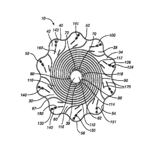
Referring to FIGS. 1-4, a suture tray package 10 of the present
invention is illustrated. The package 10 is seen to have substantially planar
floor 30, although the floor may be bowed, curved or stepped or combinations
thereof As seen in FIGS. 1-4, floor 30 is substantially circular in shape, but
may have other geometric configurations including square, elliptical, oval,
etc., and combinations thereof, and the like. Floor 30 is seen to have top 34
and bottom 37. The floor 30 has outer periphery 40, and floor 30 is seen to
have a plurality of radially extending platform sections 42 having floor
sections 35. The extending platform sections 42 give the periphery 40 an
undulating configuration. Although not preferred, the platform sections 42
may be contained within the floor 30 without extensions. The floor 30 has
center 60. Extending upwardly from the top 34 of floor 30 about the periphery
is the optional peripheral wall 50. Peripheral wall 50 is seen to have outer
CA 02745816 2011-06-03
WO 2010/074975
PCT/US2009/067292
surface 52, inner surface 54 and top 56. The peripheral wall 50 is seen to
generally follow the contour of the periphery 40, including the sections 58 in
the undulating platform sections 42. Although not preferred, the packages 10
of the present invention may be made and used without having a peripheral
5 wall 50
Center 60 is seen to have thereabout circular central region 62.
Alternatively, central region 62 may have other configurations including
square, elliptical, rectangular and the like and combinations thereof Floor
section 38 is optionally contained in central region 62. Surrounding central
region 62 is the optional central wall 70. Central wall 70 extends upwardly
from the top 34 of floor member 30, and has inner surface 72, outer surface 74
and top 76. Optionally, all or part of the floor section 38 in the central
area 62
of the floor 30 within the wall 70 is removed to provide for a finger opening
80. Only the periphery of floor section 38 adjacent to wall 70 is shown in the
FIGS. Optionally, a plurality of removable, break-away annular sections (not
shown) surround opening 80 to allow for adjustability of opening 80 for
different size fingers. When grasping a novel package 10 of the present
invention, the health care professional would insert a finger into finger
opening 80, facilitating dispensing of sutures and manipulation of the package
10, and providing for rotation of package 10 about the finger. Opening 80
may also be utilized as an opening for a spindle or other mechanical device to
facilitate automated suture loading into package 10 on a loading or winding
machine. Referring to FIG. 6, an optional spindle structure 250 is seen to
have
a flat annular base plate member 252 with opening 254 therethrough, and top
255 . A plurality of cantilevered members 260 having living hinged ends 262
and free ends 264 extends up from the top 255 of base plate member 252
about the periphery of opening 254. The members 260 are seen to have flange
members 265 extending radially outward from the ends 264. The optional
spindle 250 is mounted to package 10 by inserting the members 260 into
opening 80 through the bottom 37 of floor 30 package 10 by deflecting the
members 260 radially inward, and pushing the members through until the
flange members 265 extend over the tops 76 and 94 of walls 70 and 90,
CA 02745816 2011-06-03
WO 2010/074975
PCT/US2009/067292
6
respectively. The package 10 is then able to rotate about spindle structure
250.
Extending outward from the outer surface 74 of wall 70 in a
substantially spiral manner are the suture track walls 90. Walls 90 also are
seen to extend upwardly from the top 34 of floor member 30. Walls 90 are
seen to have opposed surfaces 92 and tops 94. The walls 90 are seen to have
a curvilinear configuration, although the tracks could have other
configurations such as radial, straight or angulated spokes, combinations of
straight and curved sections, pluralities of straight, angulated sections, and
the
like. A track 110 is seen to be formed between each pair of walls 90. The
suture track 110 is seen to have bottom 112, and opposed sides 115 formed by
surfaces 92 of walls 90. The suture tracks 110 have inner ends 114 adjacent to
wall 70 and outer ends 116 adjacent to platform sections 42. Ends 116 are in
communication with platform sections 42. Each wall 90 is seen to have an
inner end 95 connected to the outer surface 74 of the wall 70. The walls 90
also have an outer end 97 that optionally connects to the inner surface 54 of
peripheral wall 50. It should be noted that the ends 95 and 97 may be free or
unattached. Each track 110 is seen to have a vacuum opening 118 in
communication with a passage or opening 39 extending through floor 30.
The openings 118 and 39 are preferably located near or inner ends 114 of
track 110, but may be located anywhere along track 110. If desired, each track
110 may have multiple openings 118 and 39. Although it is preferred to have
walls 50 and 70, those skilled in the art will appreciate that the tray
package 10
of the present invention may be utilized without one or both of these walls.
The packages 10 as illustrated are seen to have a single track 100 for each
platform section 42. Although not illustrated, an alternate embodiment of the
packages 10 of the present invention will have two or more tracks for each
platform section 42, or a track 110 may be in communication with two or
more tracks.
Part of each platform section 42 of periphery 40 is a park platform
section 100. Each park platform section 100 is in communication with a track
110. As illustrated in FIGS. 1-6, the park platform sections 100 are bounded
CA 02745816 2011-06-03
WO 2010/074975
PCT/US2009/067292
7
by the surfaces 92 of opposed track walls 90 and the inner surface 54 of
section 58 of outer wall 50. The park platform sections 100 are also seen to
be
located in floor sections 35 of floor 30. Park platform sections 100 can also
contain optional structures such as conventional needle parks for receiving,
holding and retaining surgical needles. As seen in FIGS. 1-6, the package 10
of the present invention contains optional needle park 120. The needle park
120 is seen to have three members 130, 140, and 150, respectively. Member
130 extends up from top 34 of section 35. Member 130 has cantilevered arm
132 having radially inwardly extending section 134, downwardly extending
arm 136 having end 138. End 138 can move in opening 112 in floor section
35 when deflected. Adjacent to member 130 is member 140, which also
extends up from top 34 of flow section 35. Member 140 is similarly seen to
have inwardly extending section 144, downwardly extending arm 146 having
end 148. End 148 can similarly move in opening 112 in floor section 35 when
deflected. On the radially outward side 141, the engagement edge 143 is seen
to extend radially outward along the outward side 141. Member 150 extends
up from surface 34 of floor section 35 in alignment with member 140.
Member 150 has on the radially outward side 151, the engagement edge 153,
which extends radially outward along the outward side 151. The needle park
120 as illustrated is capable of receiving two surgical needles in openings
124
and 126, however it will be appreciated by those skilled in the art that
similar
needle parks may be utilized that are designed and constructed to hold one
surgical needles or multiple surgical needles (i.e., in excess of two). Other
types of conventional needle parks may also be used in the packages 10 of the
present invention, including foam or plastic members with slits, grooves, or
clips. It is also possible to utilize the tray packages 10 of the present
invention
without needles parks, e.g., with ligatures or unarmed sutures. The needle
park 120 is particularly useful for double-armed sutures, i.e., sutures having
surgical needles mounted to both ends.
Adjacent to the needle park 120 in platform section 42 is the optional
pledget park 160. Pledget park 160 is seen to have a pair of opposed walls
170 having inner surfaces 172 and outer surfaces 174 and tops 176. The walls
170 extend up from surface 34 of floor section 35 and are seen to be angulated
CA 02745816 2011-06-03
WO 2010/074975
PCT/US2009/067292
8
with respect to each other, but may also be parallel. Extending inwardly from
the inner surfaces 172 are the optional ridge members 174. Spaces 177 are
contained between ridge members 174 for receiving a pledget member 230.
As seen in FIGS. 5 and 6, an optional cover 190, having top 192, bottom 194
and periphery 196, and optional opening 198, may be mounted to the top of
package 10. Preferably the cover 190 is mounted to the walls 90 by affixing
the bottom 194 to the tops 94. This maintains sutures loaded into the tracks
110 within the tracks in the event that a loaded package 110 is inverted, as
well as during shipping, handling and processing.
Referring now to FIGS 5 and 6, the double armed suture 200 loaded
into the packages 10 of the present invention is seen to have suture strand
210.
Strand 210 is seen to have opposed ends 215. Mounted to each end 215 is a
surgical needle 220. Surgical needles 220 are seen to have curved, elongated
bodies 221 with distal piercing points 222 and proximal suture mounting ends
225. Needles 220 have conventional bore holes (not shown) drilled in their
proximal ends 225 to receive the suture ends 215 to which they are mounted
by conventional securing methods such as mechanical swaging. Also
mounted to the central section 218 of sutures 210 are the conventional pledget
members 230. Pledget members 230 are attached or affixed to the central
sections 218 of sutures 210 in a conventional manner such as by threading the
suture material through slits or holes formed within the pledgets 230. The
pledgets 230 may be attached in conventional manners such as by gluing or
mechanical fixation. Alternatively, pledgets may be slidably affixed to the
suture 210 by for example threading.. Pledget members 230 are seen to be
substantially rectangular members having thread openings 235 therethrough.
The pledget members 230 may have any conventional shape, in addition to the
shape shown.
As seen in FIGS. 5 and 6, the package 10 has a plurality of sutures 200
and surgical needles 220 mounted therein. Each suture strand 210 is mounted
in an individual track 110, with the suture strands resting upon the bottoms
112 of the tracks 110, and partially upon the top of sections 42. The needles
220 are seen to be mounted in the needle parks 120, with one needle in
CA 02745816 2016-04-19
9
opening 124 and one needle in opening 126 of each park 120. The pledget
member 230 for each suture strand 210 is seen to be mounted in pledget park
160 in spaces 177.
The sutures 200 are loaded into the tray packages 10 in a number of
conventional manners. For example, the package 10 may be mounted to a
conventional fixture. Then, the needles 220 are mounted in the spaces 124
and 126, respectively, in the parks 120. The optional pledget members 230
are mounted in spaces 177 of pledget park 160. Next, a vacuum may be
to applied to the openings 38 and 118 drawing or moving a looped section
212 of
the suture strand 210 into the track 110. It is preferred that the covers 190
are
mounted to the packages 10 prior to vacuum loading the suture strands 210,
although optionally a flat fixture may placed over the tops of the tracks in
contact with the top surfaces 94 of walls 90 during vacuum loading, and
Is removed after loading for subsequent application of a cover 190.
Alternatively, the suture may be placed into the package by a stylus loading
technique such as those described in US5660024, US5664404, US5491954,
US5491955, US2004/0177594, or US2002/0069617.
20 Before or after the armed sutures 200 have been loaded into the trays
10, the optional covers or lids 190 are affixed in a conventional manner. For
example, the cover 190 may consist of a heat sealable paper which is mounted
to the top surfaces 94 of the spiral walls 90 and heat is applied in a
conventional manner via, for example, conductive heat or ultrasound, along
25 with pressure to the heat sealable paper. Alternatively, if cover 190 is
made
from plastic, it may be welded to the top surface of the spiral tracks.
Alternatively, the cover 190 may be mounted via conventional mechanical
fixation such as rivets, tabs, etc. Covers 190 are seen to have a central
opening 192 and an outer periphery 194 with undulations 196 that correspond
30 to the platform sections 42 adjacent to the corresponding undulations of
periphery 40. It is also possible and desirable to optionally label each
platform
section 42 with a number. This can be accomplished in a variety of ways
CA 02745816 2016-04-19
including molding numbers into the floor 32, and labeling the top 34 of floor
30 in platform sections 42 by printing or applying labels.
It is desirable for each suture 200 to be numbered. This can be
5 accomplished as illustrated in FIG.6 by printing a number or otherwise
labeling a number on the cover 190 adjacent to each platform section
After the optional covers 190 are affixed or mounted to the packages
10, the loaded packages 10 are loaded into conventional outer packages such
10 as TyvekTm envelopes, foil pouches, thermoformed trays, and the like for
sterilization. Conventional sterilization processes may be utilized on the
packages 10 of the present invention loaded with sutures 200 including
sterilant gas (e.g., ethylene oxide), gamma radiation, plasma and the like.
Those skilled in the art will appreciate that it could be possible to use
autoclaving, depending upon the material characteristics of the sutures 200
and package 10.
The novel tray suture packages of the present invention have many
advantages that include the ability to bring the packages to be brought closer
into the surgical site. In addition, the packages of the present invention can
be
held with one hand by the health care professional while performing other
tasks. The package of the present invention permits the health care
professional to rotate the package to dial the next suture easily, and this
can be
accomplished using one hand. The novel packages of the present invention
enable health care professionals to easily keep track of the number of sutures
being used, and the packages further provide for both 'right-handed' and 'left-
handed' needle arming. The packages of the present invention holds pledgets
in place without physical deformation within the package, and the novel
packages of the present invention further prevent sutures from kinking and
provide for smooth tangle free dispensing from the package.
Although this invention has been shown and described with respect to
detailed embodiments thereof, it will be understood by those skilled in the
art
that various changes in form and detail thereof may be made without departing
CA 02745816 2016-04-19
11
from the scope of the claimed invention. The scope of the claims may be
given the broadest interpretation consistent with the description as a whole.