Note: Descriptions are shown in the official language in which they were submitted.
CA 02746029 2011-07-11
APPARATUS AND METHOD FOR REPLACING A ROTTED PORTION OF A SUPPORT
POST AND SECURING THE POST TO A SURFACE OR PIER
BACKGROUND OF THE INVENTION
1. Field of the Invention
The present invention generally relates to post support devices and methods
for
wooden support posts that are typically connected to concrete piers or other
surfaces
such as wood porches, balconies or surfaces where water or moisture pervades
the
environment, and more particularly to post support devices and methods to
minimize or
repair rotting at the base in such wooden support posts because of prolonged
exposure to
the elements.
2. Description of Related Art
In the field of construction there is a common problem of wood support posts
rotting at the base because of prolonged exposure to the elements. These posts
may be
connected to concrete piers or other surfaces such as wood porches, balconies
or any
surface where water or moisture pervades the environment.
End grain of dimensional lumber has a natural capillary structure that aids
the tree
when it is living but which can be detrimental to wooden structural members if
kept
constantly wet. Water is sucked up by the end grain thus creating an optimal
environment
for rot and mould to establish itself and eventually destroy the integrity of
the support post.
1
CA 02746029 2011-07-11
In other environments, pests such as termites are the threat. Open access to
wood fiber at ground or surface level allows termites to gain access to a food
source and
begin their destructive work.
Support posts that are structurally compromised at the base can be a very
expensive problem to fix. Support posts are often in such sizes as 6x6
(inches)
dimensions or greater and are usually well connected into a supported framed
structure
above the remote end of the post making their removal laborious and costly.
These support posts rest upon concrete piers below porches, or decks or other
similar structures, or they can be resting on the top decking surface of a
porch and may
be turned on a lathe, shaped and painted for decorative or cosmetic effect, in
addition to
supporting a roof structure above.
Rot and termite damage tends to progress up the inside core of a post much
like a
cone. This means that while a small area of rot may be visible from the
exterior, the rot
may extend much higher within the post.
There are a number of examples in the prior art of elevated post support
devices
designed to be used during new construction where easy installation is
possible because
the support post has not yet been installed into the structure. One can easily
gain open
access to the bottom of the post or the device is already secured to a
concrete footing and
the post can be dropped into position over the device.
However, if a rotted post is to be repaired, the prior art envisions that the
rotting
post be completely removed from the structure first and that a new post be
installed in the
same fashion and procedure as if it were new construction. The prior art
envisions that
the method of installation or repair accommodate to the height restrictions of
the device
2
CA 02746029 2011-07-11
rather than the device being capable of adapting within a typical and modest
height range
of rot within a post.
This means that the repair solution required when using the prior art devices
necessitates complete removal of the post, which entails new material cost and
labor.
The prior art devices and methods do not lend themselves easily to situations
where one
desires to remove only the rotted portion of the post so that the rest of the
post can be
saved, thereby reducing replacement cost and labor. And yet this is a
desirable choice
given the high cost of replacing large structural posts that are typically
securely connected
to the remaining framing structure above while only five or six inches of rot
exists at the
bottom.
The prior art devices are only designed to provide a support post sufficient
building
code mandated clearance of at least one inch for all non-preservative treated
ends of
posts. But once rot sets in it almost always extends further than one inch
from the surface
of the grade. In fact the extent of rot may vary significantly depending of
many factors
such as snow and ice accumulations, direct or indirect exposure to rain or
moisture.
While the prior art devices could be modified to accommodate whatever height
one
might anticipate rot could extend to, doing so would require numerous
different height
sizes to be made in anticipation of varying extents of rot. Or a single design
which might
be tall enough to function in a less common situation where the rot extends
far above
average heights might also be contemplated to cover as many instances as
possible.
But such a device would be more than is required in many other instances, thus
would be more expensive to manufacture. That is perhaps one of the reasons why
the
3
CA 02746029 2011-07-11
prior art has focused on devices which only meet the minimum building code
elevation of
one inch above a surface.
Another problem with the prior art devices is that they do not allow for
variability
during the installation, even within a reasonable range, so that the height at
which a rotted
post is cut is close to where healthy wood begins to predominate. The prior
art devices
offer no range of elevation in which to work beyond their discrete height.
The prior art devices are designed so that they connect to the post by way of
external vertical planer surfaces that run up along the wall of the post and
are secured to
the post with fasteners. As a result, there is no seal to prevent water from
seeping in
between the post and the vertical planar surface. They are simply compressed
against
the post and screwed in place. As a result moisture is retained longer between
post and
planar surface and can gain access to the core of the post through the entry
point of the
fastener. These weaknesses leave the new post no better protected from
moisture
damage and eventual structural decay than the previous post with the same
supporting
device.
Some prior art (Scholl) devices are designed to protect a pier and a post
combination by using compressive means around a post to create a seal in
combination
with a large cavity that encircles post and pier. It does not envision a
mechanical seal
which cuts into and penetrates beyond the plane of the post wall. This is
clearly
advantageous given its permanency and long term reliability when compared to
applying
caulking around the perimeter of the post where the support device planar
surfaces
terminate.
And yet one more factor is ignored by the prior art which renders their use
ineffective or impractical in repair or renovation situations long after
original construction.
4
CA 02746029 2011-07-11
These are instances where a post to be repaired has been connected to a
concrete
surface by way of a device which has some kind of appendage or leg embedded
into the
concrete. This occurs at the time of construction whereby an anchoring
appendage is
submerged into wet cement and left to cure.
If one of the prior art devices were desired to be used in such a repair
situation, it
would entail cutting off the embedded appendage and removing a portion of
concrete
sufficient for another like device to be embedded within new cement poured
into this
cavity within the pier. This would be laborious, costly and time consuming. A
device that
is surface mounted to cured concrete would be the only reasonable solution
even though
the old embedded anchoring appendage would still have to be cut off.
To further demonstrate the utility and benefit of having a device with both
variability
in height range and a means of sealing and protecting the connection between
post and
device, consider one element of a repair technique that would be part of the
method used
when employing such an ideal device.
A simple method of fixing a rotted post that sits directly on a surface,
without any
kind of post support anchor, is to cut the post above the rotted portion and
remove it. A
new replacement filler block could be cut from identically dimensioned lumber
so that it
would fit snuggly within the void. Construction adhesives may be applied to
the contact
surfaces of the end of the old post and replacement filler block. However,
this would likely
doom the filler block to the same fate as its predecessor given that exposure
to the
elements would continue at the post to base surface interface and also at the
joint
between the filler block and post.
Alternatively, a traditional metal post support device could be used to secure
the
replacement filler block whereby screws pass through it into the filler piece
connecting the
CA 02746029 2011-07-11
two. The support device with the attached filler block can now be fitted
underneath the
hanging post and fastened to the concrete pier. In such a case, the height of
any post
support device would also have to be accounted for so that it and the filler
block closely
filled the void.
From a functional perspective, these two solutions, however crude, would at
best
address the compression strength required of the adapted support post.
However, the
lateral strength would still be a concern given that adhesive is all that
binds the filler block
and post.
This concept does offer some cosmetic benefits as it creates a support post
with
an identical profile as the original post. Further sanding and use of resin
fillers and
painting can result in a high quality aesthetic finish close to the original.
However the
joints or interfaces between surface, filler block and post remain exposed to
the elements.
If the joint is not repaired properly and it remains close enough to the base
surface
such that it is within the zone of exposure to the elements, the process of
rot is set to
repeat itself once again. This concept is incomplete and far from optimum.
In summary, there remain significant issues of concern with this method of a
repair
such as inadequate lateral or torsion strength at the union of the old and new
filler
material, lack of protection of the union interfaces from further exposure to
the elements or
pests, and keeping the base of the filler block post bottom dry.
Therefore there is a need for an elevated surface mounted post support device
that a) addresses the need for a permanent and reliable long term mechanical
sealing
system between post walls and the vertical planar surfaces of the device that
connect to
and secure the post; b) provides a high degree of compression, lateral impact
and torsion
6
CA 02746029 2011-07-11
strength; c) meets the minimum building code gap requirements between post and
surface; and d) can be used in a range of situations where the progression of
rot within a
support post extends to varying heights.
The devices and methods of the present invention are provided to fulfill one
or
more of these needs as will be understood from the following description.
SUMMARY OF THE INVENTION
In order to address some of the shortcomings in the prior art, some aspects of
the
present invention provide a post support device that enables a rotted base
portion of a
wooden support post to be removed in situ and the remaining end of the support
post to
be secured for regained structural integrity, the device comprising a base
adapted to being
attached to the surface; elevation support means in cooperation with the base
for
supporting the post or a filler block if one is used in a position above the
base; at least two
cover plates, each cover plate being adapted to covering a portion of the
exterior of the
post, each cover plate further including an elongate flange portion facing
inward towards
the post and being positioned generally transverse to the longitudinal axis of
the post, said
flange portion including a leading cutting edge to enable the flange portion
to bite into the
surface material of the post upon the application of force to the flange
portion to provide a
mechanical seal between the flange portion and the post; first fastening means
for
securing each cover plate to the post; and second fastening means for securing
the base
and the elevation support means to the post or the filler block if one is
used.
7
CA 02746029 2011-07-11
In some embodiments, the cover plate may define a top edge and the flange
portion may be adjacent the top edge, the top edge may further include at
least one V-
shaped cutout to enable the flange portions on either side of the cutout a
limited range of
movement relative to each other.
In some embodiments, the elevation support means may comprise a raised area
embossed into the base. In some embodiments, the elevation support means may
comprise a formed member being connectable to the base and having an
elevational
thickness that supports the post or the filler block if one is used in a
position at that
distance above the base. Preferably, the elevational thickness is at least one
inch.
In some embodiments the device may further include upwardly extending tabs on
an upper surface of the base wherein the tabs are located on the inside and
are aligned
with the cover plate when the device is assembled, and third fastening means
for securing
each cover plate to at least one of said tabs.
In some embodiments, the elevation support means may define a periphery that
is
smaller than the periphery of the post or the filler block if one is used.
In some embodiments, the cover plates together in the assembled device
completely envelope the periphery of the post. In some embodiments, each cover
plate
may further includes complementary overlapping side edges at each end, one
being an
underlying edge and the other being an overlying edge, wherein the overlying
edge of one
cover plate overlaps with the underlying edge of the adjacent cover plate.
Fourth
fastening means may be included for interconnecting the overlapping side edges
on
adjacent cover plates and simultaneously securing them to the post.
8
CA 02746029 2011-07-11
Preferred embodiments may comprise several components; a planar base with
either an integrally formed elevated zone contained within the periphery of
post walls or a
separate component that creates a taller space between the planar base and the
post,
either of which would connect to the post bottom elevating it from the
surface; at least two
post cover panels that wrap around the post above and below a joint between a
new filler
block material and the original post (if a filler block were used); inwardly
bent sharp edges
adjacent the upper edges of the cover panels which can be driven or impaled
into the side
wall of the post to create a mechanical seal; and fasteners to connect the
parts to each
other and to the post.
The devices of the present invention could be used in new construction
applications where a filler block would not be necessary as the device would
be screwed
directly onto the end of the new post followed by the cover panels.
Thereafter, the new
post and base support device could be fastened to the concrete pier. However,
the
devices' full potential, greatest value and most unique attributes are fully
realized when
used to repair old rotted wooden support posts.
The planar base surface separates the bottom of the post from the concrete
pier or
deck surface to which it connects, and where moisture or pests typically
reside. At a
minimum this planar base surface would be elevated at least ' inch by virtue
of
embossed or stamping the base material. The planar base may connected either
directly
to the end of a new post or to a replacement filler block by conventional
fastening means.
In the case of repair of an old post, the filler block fits directly
underneath the cut end of
the old post.
In another embodiments there may be a separate component sometime called a
"stand off' that lifts the post higher above the concrete surface. Ideally
this space should
9
CA 02746029 2011-07-11
at least meet the building code minimum standard of 1" for use with un-treated
post ends.
This "stand off' component is preferably made of square or rectangular tubing
or could be
made of stamped metal or an injection molded high density synthetic material.
If it is
made of metal it would be welded to the base plate of the device. In either
case the
"stand off' component is not subject to moisture damage and serves the purpose
of
elevating the bottom of the filler block or the original post (if a filler
block is not used) to
meet the minimum building code standards.
The two post cover panels wrap around the post overlapping each other and
connecting tightly, while the upper edge of the panels have sharp inwardly
pointing
flanges or blades that cut circumferentially into the post walls creating a
mechanical seal.
Fasteners are screwed through overlapping and non overlapping portions of the
panels
above and below the filler block-to-post joint ensuring the entire combination
of post and
device becomes strong.
The ideal device is intended to connect either directly to the end of a
support post
or to a replacement filler block and the remaining cut end of a support post,
so as to; a)
provide compression, lateral impact and torsion strength; b) protectively seal
around the
post walls above the joint; and c) provide a dry and sealed joint connection
between the
bottom of the filler block and the base connection means to a surface. It does
not address
the issue of providing a compressive seal while covering or sheltering an
entire post to
pier connection.
The cover panels can be designed for a standard height of approximately 6 to 8
inches, which might be sufficient for vast majority of rotted post repair
situations, or they
may be shorter or taller, as required. The elevated embossed or "stand off'
portion of the
device could remain constant. But the height of the cover panels allows for a
reasonable
CA 02746029 2011-07-11
range within which to choose exactly where to cut off a rotted portion of
post. Since the
extent of rot may differ from one post to another it is useful to have a
device which can
affordably operate and adapt in these situations.
It should be understood that the prior art post support devices are designed
to only
marginally separate a post from a surface; typically no more than one inch.
They are
designed to provide only a discrete separation between a post and surface
rendering
them ineffective in most post repair situations. And, because there is no
variability in their
application, they work best in new construction only. If they must be used for
repair work,
the entire post must be replaced with a new post. No seal is provided where
the side
members of these devices connect to the post. The side members are usually
intended to
be nailed or screw against the post wall.
As has been shown herein, the present invention with the cover panels and the
ability to use them with a custom sized filler block (within a range depending
on the height
of the cover panels) is easily adaptable to situations where much more than
one or two
inches of rot must be removed. As well, the sharp edged blade of the cover
panels creates
a reliable and clean looking seal for better protection. The concept of the
sharp edged
blade is vast improvement over any concept that provides a member that merely
sits flat
against a post wall. In such a case, a bead of caulking would have to be
applied around
the entire perimeter of the post. The caulking would account for the integrity
of the entire
seal and require frequent maintenance and attention. In contrast, the present
invention
that provides a mechanical seal for all but the very small corner portions
improves long
term performance significantly.
11
CA 02746029 2011-07-11
BRIEF DESCRIPTION OF THE DRAWINGS
For a better understanding of the present invention and to show more clearly
how
it may be carried into effect, reference is made by way of example to the
accompanying
drawings in which:
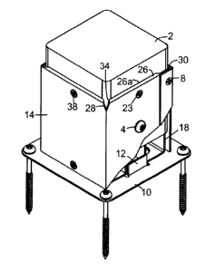
Fig. 1 is a perspective view of an embodiment of a post support device in
accordance with the present invention showing the finished appearance with the
cutting
blades of the cover panels embedded in the side walls of the post.
Fig. 2 is a perspective view of the device in Fig. 1 with a portion cut away,
partially
revealing an embodiment of the stand-off base and the post inside the device;
Fig. 3 is a perspective view of the device in Fig. 1 without the cover panels
to
illustrate how a filler block is used with the apparatus for post repair
applications and a
cutaway perspective of the filler block shows screws that come from underneath
the
stand-off and base;
Fig. 4 is a top view of the device in Fig. 1 without the post to illustrate
how the
cover panels mate at the overlaps and are fastened together;
Fig. 5 is a perspective view of a cover panel of the device in Fig. 1;
Fig. 6 is a top view of an embodiment of a flat base;
Fig. 7 is a perspective view of an embodiment of the stand-off base;
Fig. 8 is a cross section of another embodiment of a stand-off base made from
a
single piece of sheet metal;
Fig. 9 is a perspective view of the device in Fig. 1 without the cover plates;
12
CA 02746029 2011-07-11
Fig. 10 is a perspective view post on top of an embossed elevated base rather
than using the higher elevated stand-off component.
Fig. 11 is a cross section showing the device in Fig. 1 as used in new
construction
applications when a stand-off component is employed with a single continuous
post;
Fig. 12 is a cross section showing the device in Fig. 1 as used in a post
renovation
application when a stand-off component is employed with a filler block;
Fig. 13 is a cross section perpendicular to that of Fig. 12 showing the device
in Fig.
1 with a filler block and a stand-off component;
Fig. 14 is a cross section showing an embodiment of the device with an
elevated
embossed base used with a single continuous post;
Fig. 15 is a cross section perpendicular to that of Fig. 14;
Fig. 16 is a cross section showing an embodiment of the device with an
embossed
elevated base as used in with a continuous post; and
Fig. 17 is a cross section perpendicular to that of Fig. 16.
DETAILED DESCRIPTION OF THE INVENTION
For the purposes of promoting an understanding of the principles of the
invention,
reference will now be made to the exemplary embodiments illustrated in the
drawings, and
specific language will be used to describe the same. It will nevertheless be
understood
that no limitation of the scope of the invention is thereby intended. Any
alterations and
further modifications of the inventive features illustrated herein, and any
additional
13
CA 02746029 2011-07-11
applications of the principles of the invention as illustrated herein, which
would occur to
one skilled in the relevant art and having possession of this disclosure, are
to be
considered within the scope of the invention.
Referring to Figures 1-3, there is depicted an embodiment of a post support
device
in accordance the present invention. Post support device 5 comprises a base
such as
flat base plate 10 and an elevation support means in cooperation with the
base.
Depending on the application, the elevation support means may be an integrally
formed
elevated zone 11 that is embossed into the base plate 10, preferably contained
within the
periphery of post walls, that supports the post in an elevated position above
the base
hence the ground) such as, for example, by a ' inch or more. Alternatively,
the elevation
support means may be a separate formed member being connectable to the base
and
having an elevational thickness that supports the post or the filler block if
one is used in a
position at that distance above the base. An example of a separate formed
member is
stand-off component 18 which creates a taller space between planar base 10 and
post 2.
Stand off component 18 may comprise a pair of square or rectangular tubes that
are
joined to the base 10, as shown. Either of these structures - the elevated
zone 11 and the
stand-off component 18 - elevate the bottom of post 2 from the planar base 10.
Post support device 5 further comprises a pair of cover panels 14 that overlap
each other on two faces along complementary overlapping side edges or tabs 30
and 32:
tab 30 defining an underlying edge and tab 32 defining an overlying edge. Each
cover
panel 14 has planar sides that are perpendicular to each other, each side
having a width
dimensioned to cover the corresponding sides of the post 2, and a typical
height of 6 - 8
inches, or as required for specific applications. Along the top edge of each
side of the
cover panel 14 is provided a flange 26 bent inward along the top at
approximately 90
degrees to the side (hence the post) having a sharp cutting edge 26a that is
adapted to
14
CA 02746029 2011-07-11
cut across the grain (transverse to the longitudinal axis of the post) into
the side wall of the
post 2, thereby the flange 26 functions as a blade.
There is also provided a "V" cut 28 at the corner of the vertical bend in each
cover
panel 14 which is of sufficient size and depth to permit easy independent
lateral
movement of the adjacent portions of the planer surfaces of the cover panels.
The "V" cut
is important because, during the installation of the cover panel 14, lateral
strikes with a
hammer to the top portions of the sides on the cover panel are required to
engage the
cutting blade 26 into the side wall of the post, and the "V" cut 28 enables
the adjacent top
portions of each side on the cover panel 14 to be driven inward.
Furthermore, the side corners 34 of each flange or blade, adjacent to the "V"
cut
28, are preferably cut at an angle greater than 90 degrees to the cutting edge
26a, more
preferably greater than 110 degrees, so that the side corners 34 more easily
initiate
engagement of the blade into the wood. Installation requires that the bend
line at corner
of the cover panel 14 and the post corner be aligned with each other. Once
they are in
close proximity to one another, a light to moderate strike of a hammer at the
corner near
the "V" cut 28 of the cover panel 14 is sufficient to engage the two adjacent
corner points
34 of both cutting blades 26 across the longitudinal grain of the post.
Further strikes along
one cutting blade 26 at a time to the end of each cover panel 14 will set the
blade 26 into
the post. First fastening means such as wood screws 23, just below the top
edge and
approximately at mid span of the cover panel 14, may be inserted through holes
38 and
used to fully pull the cutting blade into the post to provide a water tight
seal.
The impaling the cutting blades into the side walls of the post is more like a
clamping action with a hinge in vertical alignment with the corner of the post
whereby the
cutting edges 26 are initiating the cut into the post near the corner of the
cover panel 14
CA 02746029 2011-07-11
and post. Therefore the angle of each corner 34 assists in making the initial
cut into the
wood in cleaner manner than if the corner were a 90 degree corner. With a 90
degree,
corner the wood fiber is more apt to be ripped and crushed as the point at the
corner 34 of
the blade 26 arcs around the hinge point into the side wall of the post.
Whereas, with the
angled corner 34, the cutting edge 26a of the blade 26 is better able to cut
the wood grain
progressively as it moves across the width of the post. The result is a clean
entry point of
the blade 26 into the wood at both visible "V" cuts in the post.
Fourth fastening means such as self drilling screws 8 may be used to fasten
the
cover panels 14 together at overlapping tabs 30 and 32, and to the post. A
larger screw 4
is shown in the middle of the cover panel which can be used if desired in
applications
requiring increased strength, such as, for example, in hurricane environments.
An
optional third fastening means such as self drilling screw 33 may be used at
the base and
mid span of the cover panel which fits through a hole in the cover panel and
then self drills
and taps into a vertical tab 12 formed in the base 10. In this manner, a
complete seal is
made around the periphery of the post, except for the small V cut openings 28
at the
corners, for a support base that is dry, water resistant, and has excellent
compression,
and torsion strength.
Referring to Figures 4 and 5, further illustration of the self drilling screws
8 and the
cover panels 14 are provided. The screws 8 are installed through holes 35
along the
overlapping tabs 30 and 32 locking the cover panels together and creating a
strong and
rigid shell that completely surrounds the base of the post. The cover panels
abut
themselves up against the vertical tabs 12 formed into the base 10 as they are
placed in
position around opposing corners of the post. The vertical tabs are closely
aligned with
the plane of the post walls so that they contact or come close to contacting
the back side
of the cover panels 14. Self drilling screws 33 can also be inserted through
holes 37 at
16
CA 02746029 2011-07-11
the bottom edge of the cover panels 14 to fasten the panels to the vertical
tabs 12 and the
base 10. The holding power of this fastening means is in addition to the
second fastening
means such as larger pan head screws 19 that secure the post or a filler block
21 to the
stand-off component 18 and the base. In some environments where hurricanes are
possible, it may be necessary to use a middle hole 36 that may be provided in
the center
of the cover panel and drive a larger fastener 4 through and into the post
from opposing
sides to provide additional lateral means of support from vertical lift from
high winds. The
screws 23 along the top edge of the cover panels also act as lateral fastening
means to
the post but the addition of the larger fastener 4 offers additional strength
if needed.
Once the blades 26 have been firmly embedded into the respective sidewalls of
the posts, a complete water seal has been achieved around the post except for
the small
"V" shaped openings 28 at the corners of the panels. These small areas are
sealed with a
small dab of exterior caulking to complete a perfect watertight seal. These
caulking points
can be inspected annually, and because of their small size, can easily be
peeled away
and new caulking applied if necessary.
A benefit of the waterproof shell around the base of the post that the cover
panels
14 provide is that the end grain of the post is in a protected zone above
where any water
may pool. All side installed screws are also sealed effectively by the tight
tolerances of
the through holes and, since water cannot dribble down between the cover
panels and the
post walls, it cannot also find its way into the penetration holes in the
post. Snow and ice
or heavy rains have no effect on the integrity of the base and lower zone of
the post that
would otherwise be exposed when using the support bases found in the prior
art.
Referring to Figures 6-8, the base 10 that is used in conjunction with the
stand-off
component 18 has large holes 16 in the inner zone that allow the larger heads
of
17
CA 02746029 2011-07-11
fasteners 19 to pass through and into the tubular formation of the stand-off
component 18.
A similar sized hole 20 is aligned directly over holes 16 in the base with
smaller holes 22
directly above permitting the screw 19 to penetrate the bottom face of the
post 2 or a filler
block 21. The stand-off tubes 18 being welded to the base 10 form an integral
unit that
can be designed to any height, but preferably at least 1" above the base to
comply with
certain building code standards for untreated wood posts.
Another simple configuration of base and stand-off component entails forming
both
tube shapes from a single piece of sheet steel and welding it to the top
surface of the
base 10.
Also in Figure 6 are shown the vertical tabs 12 which are ideally formed from
the
same material as the base to save time and effort. The smaller outer holes 7
allow for
wood screws or concrete fasteners to protrude through and secure the base to a
surface.
There are basically two scenarios where the device is designed to be used: in
post
repair situations and in new construction. Post repair situations will require
that the rotted
lower portion of the post be removed with a saw, preferably with a right
angled cross cut
that allows a similarly dimensioned piece of lumber or similar materials (i.e.
filler block 21)
to fit between the remote post end and the stand-off component 18 or elevated
embossed
base 11, as the case may be depending which embodiment of the base 10 is used.
Either
the stand-off 18 or embossed base 11 embodiments may be used in new
construction but
the stand-off provides better protection from moisture given the higher
elevation. When a
new post is used with either the stand-off 18 or the elevated embossed base
11, the cover
panels 14 function in the same manner by wrapping around the post, overlapping
along
their respective side edges (overlapping tabs), with the blades 26 penetrating
the post
walls.
18
CA 02746029 2011-07-11
For post repair scenarios, the height of the cover panels can be adapted to
varying
lengths to accommodate a range of common rotting patterns and depths. The
benefit to
this well appreciated by both homeowners and builders who face a situation of
having to
extricate a tall, heavy support post built into the framing of an upper deck
or balcony. The
only portion of the post that is damaged is typically the lower few inches and
which
requires repair. By using the stand-off embodiment of the device the damaged
portion is
easily cut off and the original mounting bracket cut off from the concrete or
wood surface
as well using a reciprocating saw with a metal blade. The filler block 21 is
fastened first to
the stand-off 18 with the screws 19 and cut to precise height so that when the
block 21
and the device are inserted into the opening beneath the cut post there is
reasonably tight
fit. A small amount of heavy duty construction adhesive can be applied between
the
mating surfaces of the post 2 and the filler block 21 to enhance the union.
Once the cover
panels 14 surround the union between post 2 and filler block 21, the post and
support
base become one rigid unitary piece whereby both compression loads and torsion
loads
are effectively resisted and withstood. Since the top end of the post remains
fixed above
into the framing of the upper deck the post remains very strong and resistant
to lateral
loads at the top or bottom ends of the post. In effect, the integrity of the
post and deck or
balcony has been restored and the lower region of the post will remain dry and
healthy for
long periods of time. The appearance of the finished application is improved
beyond that
offered by solutions found in the prior art, which may be appealing to a
certain segment of
the population.
Referring to Figure 9, there is depicted a transparent perspective view of the
various components of the apparatus showing the relation of post connection
means to
the base and stand-off 18. This view without the cover panels 14 reveals how a
filler-
block 21 can also be employed easily to adapt to the varying and unpredictable
range of
19
CA 02746029 2011-07-11
rot within old posts yet commonly within the range of heights of the cover
panels that are
manufactured. This view also depicts the fact that in the ideal device, the
stand-off
component 18 or the periphery of the flat elevated zone 11 of the embossed
base lies
within the periphery of the post or filler block walls. This ensures that if
water somehow
gained access on the inside the cover panels, that it would be free to drip
down to the
basel0 surface and keep the bottom of the post dry.
Referring to Figure 10, there is depicted a similar perspective view to
illustrate the
relative positions of the post overtop the embossed version of the base 10.
Vertical tabs
12 are shown in this illustration but are optional if a single continuous post
application is
employed. This is because the post can be firmly secured to the base 10 by
fasteners 19
from underneath the base. However, in a post repair application it is possible
that the tabs
12 may be used for two purposes. First they may serve to provide some
alignment
assistance of the panels to the base 10 but largely that is provided for if
the filler-block 21
is centered evenly over the elevated zone 11 of the embossed base. Secondly,
the cover
panels are secured to the post by upper screws 8; then secured to the lower
filler block by
two optional side screws 4; the filler-block further fastened to the base by
large screws 19.
Lastly, the cover panels may be mechanically secured to the base 10 by using
self drilling
screws 33 to penetrate the vertical tabs 12 of the embossed base 10.
Referring to Figures 11 and 12 there is depicted a cross sectional view
showing
how the apparatus is used in new construction applications when a stand-off
component
18 is employed. The cutting blades 26 are fully embedded into the side wall of
the post.
Wood screws 23 are shown also penetrating the side of the post 2. The heads of
the-
larger screws 19 are shown inside the stand-off tubes 18. Self drilling screws
33 are
shown at the base of the cover panel penetrating through the vertical tabs 12
and into the
side of the stand-off. Not only is the post secured laterally to the cover
panels and the
CA 02746029 2011-07-11
base 10 by virtue of the stand-off component 18 but also by the lower lateral
screws 33
through the panel and into tab 12 panel near the base 10. Figure 9A shows how
the
apparatus is used in post repair applications using the original post and a
filler-block 21.
Referring to Figure 13, there is depicted the same apparatus and post
configuration as in Figure 12 but rotated 90 degrees showing the other side of
the stand-
off 18 and providing a view of the overlapping fasteners 8, top mid span
fasteners 23, and
optional side screw 4.
Referring to Figures 14 and 15, there is depicted cross sectional views
showing
how the apparatus is used in new construction applications when an elevated
embossed
base 10 is employed with a single continuous post 2. Fasteners on the sides of
the cover
panels are not shown in this view in order to emphasize the fastening means at
the
bottom of the post. The heads of the larger screws are shown fitting inside
the cavity
under the elevated base. Figure 15 shows a view that is rotated 90 degrees and
illustrates the positions of the various side fasteners through the cover
panels. The view
begins on the left from the V cut corner of the post thus by-passing the left
cutting blade.
Referring to Figures 16 and 17, there is depicted cross sectional views
showing
how the apparatus is used in post repair applications when an embossed 11
elevated
base 10 is employed. The cutting blades 26 are fully embedded into the side
wall of the
post. The heads of the larger screws 19 are shown fitting inside the cavity
under the
elevated base. Figure 17 is another cross sectional view of a the same
apparatus but
rotated 90 degrees to show the details of the screws 8 that secure the cover
panels 14
together, the mid span screws 23 that pull the blades 26 in tighter against
the post walls
and the optional screw 4 in the middle of the cover panel. The cross sectional
view of the
21
CA 02746029 2011-07-11
left side of the apparatus also begins between the V cut at the corner, thus
omitting the
view of the blade 26 on this view.
The following describes both the characteristics of the device and the method
of
employing it.
The first step of using an embodiment of the present invention is to locate a
support post with a rotted bottom portion. The extent of the rot must be
determined and
one should allow a zone of safety of at least 1 inch above the rotted area. A
horizontal
line is circumscribed around the post. The structure above the post should be
temporarily
supported by another post while the rotted portion is cut off, preferably with
a reciprocating
or circular saw. The void between the post end and the surface of the grade or
concrete
is accurately measured. With the elevation of the base of the device in mind,
either with
an embossed surface or a "stand off' component, the height of the filler block
must be
accurately measured so that the combined heights of base of the device and
filler block
exactly match that of the void. Depending on the embodiment of the device, the
filler
block is either a) secured to the embossed base of the device by standard
fasteners that
screw up through the support base of the device from underneath its bottom
surface; or b)
secured to the "stand off' component which is welded to the base plate to
create a
minimum one inch elevation above the concrete grade. The filler block would
usually be
identical nominally sized lumber as that of the post but could be any high
density synthetic
material.
It is the cover panels in conjunction with the post base device and filler
block that
provide the heretofore unaddressed benefits of improved lateral and torsion
strength, a
near perfect mechanical seal (except for the small exposed corner portion
which is
22
CA 02746029 2011-07-11
covered by a dab of caulking) and the freedom to variably select where to cut
the old post
within the range of the height of the panels while removing the rotted
portion.
It should be noted that a variety of flat planer bases that elevate the end of
the filler
block above the surface could potentially be used with the post cover panels
and achieve
the effect of maintaining a firmly connected base to surface grade connection.
But it is the
design of the base of this device in concert with the cover panels which
provide additional
protection against any water or moisture that may accumulate on the surface of
the base
proximate to the end of the post or filler block.
An embossed elevated base would provide a minimum level of protection from
surface moisture. A "stand off' component would provide a greater level of
protection with
building code standards in mind. A "stand off" component with a filler block
would provide
even greater protection to a repaired post. In any of these three scenarios,
the post cover
panels provide protection from water and insects and provide excellent torsion
and lateral
strength.
Construction adhesive is applied to the top surface of the filler block. The
support
base with attached filler block is then fitted into the void. Any excess
adhesive that is
squeezed out can be wiped off for a clean installation. The support base
itself has either
an embossed elevated center portion or taller "stand off' component, the
perimeter lines
of which lie within the periphery of the bottom of the filler block to
encourage water and
moisture to drain freely and cleanly away from the its bottom if moisture or
water ever
gained access to this area. This also ensures that if water accumulates on the
base of the
device that the end of the post or filler block would still remain elevated
and dry. It also
ensures that if any moisture or condensation ever found its way into the
concealed area it
would drip cleanly from the edge of the block to the base below.
23
CA 02746029 2011-07-11
In addition, vertical tabs creating a surface area formed into the base
proximate to
the periphery of the elevated portion. This surface aligns within the
periphery of the filler
block walls so that the inside face of the post cover panels in turn make full
contact with
the surface of the tabs. Optional screws can be driven through the bottom edge
of the
cover panels into the vertical tabs. This option may provide further strength
to the entire
assembly but may be unnecessary.
Once the base and filler block are situated directly under the post to be
repaired,
the first section of the post cover panel which resembles a corner section is
placed
roughly in position at one of the corners of the block and post. The panel is
moved closer
into the corner of the post until the sharp edges of top horizontal flanges or
blades make
contact with the post walls above the joint connection. The shapes of the
cutting edges of
the blades are designed to cut into the side wall of the post from an initial
impact of force
directed at the corner bend. The force sets the corner of the panel tight
against the post
where there is no blade. The blade corners are angled (not perpendicular) to
the cutting
edge of the blade - i.e. the edge of each corner has is at an angle 41 greater
than 90
degrees to the cutting edge of the blade flange, preferably greater than 110
degrees, or
about 135 degrees. The angled corner edges facilitate the blade to both cut
into the post
and move tangentially along the side of the post. Once the corner and first
part of the
blade are set, a direct impact against the post sets the rest of the blade.
This does not
require excessive force as it only needs to cut about 1/8" or less into the
post to create a
mechanical seal. This method is important so as to set the corner of the panel
and the
blades tightly against the corner of the post before setting the rest of the
edges of the
blade into the post. The small gap or break in the seal at the "V" cut in the
corner of the
panel where the flanges do not extend to is later sealed with a small dab of
exterior
caulking. A reliable long term mechanical seal is thereby been completed.
Caulking is
24
CA 02746029 2011-07-11
used only as it is intended to be used - in small discrete areas rather than
as the singular
critical element of any exterior sealing system.
The second cover panel is placed around the opposing corner of the post and
care
is taken to ensure that one of the vertical edges of the panel is aligned so
that as it is
driven into final position it slides underneath the overlapping portion of the
other cover
panel. Sideways force is again applied along the sharp flange ensuring a
complete
mechanical seal around the post walls and another small dab of caulking is
place at the
corner gap. The "V" cuts in the top corners of the panels allow the top
portion of each side
of the cover panel to move freely of one another towards the post wall as they
are struck
by a hammer. Usually a hammer strike is sufficient to set the blade completely
into the
post wall. If desired a single screw could also be driven through at mid span
of the top
edge of the panel.
Two self drilling screws are driven through the overlapping vertical flanges
of the
two corner panel members making the entire panel structure a single unitary
entity. This
itself provides a high degree of lateral impact and torsion strength to the
joint between the
old post and filler block. In installations where a filler block is employed,
two fasteners are
screwed through the panels into opposite walls of the upper original post to
further secure
the panel and post. This ensures that the panels are mechanically connected to
both the
old post and the filler block so that the glued joint is not the only means of
connection.
Two other fasteners may be screwed through the lower portion of the panels
into
opposite walls of the filler block (but adjacent to the previous screws) which
is in turn
connected directly to the support base by fasteners or with an intermediary
spacer of
metal or high density synthetic material. Incidentally the lateral screws also
comply with a
CA 02746029 2011-07-11
requirement under the building code for support posts if they are to meet
uplift standards
such as for hurricanes.
The repaired post has both the compression and lateral torsion strength of a
new
post because of the filler block and the wrapping panel covers. It also has a
mechanically
sealed joint that will remain dry. The only maintenance required is to inspect
the corner
dabs of caulking on an annual or bi-annual basis and repair as needed. The
post to base
to surface connection keeps the post end covered from direct exposure to the
elements
and pests, such as termites, yet it allows air flow underneath the post bottom
to ensure it
can dry out easily should water fins its way in. As well, the slim profile of
the cover panels
closely follows the vertical profile of the original post walls for an
improved aesthetic
appearance.
While the illustrated embodiments are adapted to square or rectangular support
posts, alternative embodiments of the present invention are adapted to round
posts, in
which case the cover panels would be semi-cylindrical in overall shape to
conform to the
external dimensions of a round post.
Other aspects and features of the present invention will become apparent to
those
of ordinary skill in the art upon review of the following description of
specific embodiments
of the invention in conjunction with the accompanying figures.
While the above description and illustrations constitute preferred or
alternate
embodiments of the present invention, it will be appreciated that numerous
variations may
be made without departing from the scope of the invention. It is intended that
the invention
be construed as including all such modifications and alterations.
26