Note: Descriptions are shown in the official language in which they were submitted.
CA 02746213 2011-06-07
WO 2010/077608 PCT/US2009/066992
APPARATUS AND METHODS FOR CONTROLLED RELEASE
OF TACKING DEVICES
PRIORITY CLAIM
[0001] This invention claims the benefit of priority of U.S. Provisional
Application Serial
No. 61/120,962, entitled "Apparatus and Methods for Controlled Release of
Tacking
Devices," filed December 9, 2008, the disclosure of which is hereby
incorporated by
reference in its entirety.
BACKGROUND
[0002] The present embodiments relate generally to medical devices, and more
particularly,
to devices for engaging tissue or facilitating closure of a bodily opening.
[0003] Perforations in tissue or bodily walls may be formed intentionally or
unintentionally.
For example, an unintentional ventral abdominal hernia may be formed in the
abdominal wall
due to heavy lifting, coughing, strain imposed during a bowel movement or
urination, fluid in
the abdominal cavity, or other reasons.
[0004] Intentional perforations may be formed, for example, during surgical
procedures such
as translumenal procedures. In a translumenal procedure, one or more
instruments, such as
an endoscope, may be inserted through a visceral wall, such as the stomach
wall. During a
translumenal procedure, a closure instrument may be used to close the
perforation in the
visceral wall. Depending on the structure comprising the perforation, it may
be difficult to
adequately close the perforation and prevent leakage of bodily fluids.
[0005] Attempts to seal perforations have been performed by coupling a graft
member to
tissue. For example, a graft material such as a mesh or patch may be disposed
to overlap with
tissue surrounding the perforation. The graft material then may be secured to
the surrounding
tissue in an attempt to effectively cover and seal the perforation. In order
to secure the graft
material to the surrounding tissue, sutures commonly are manually threaded
through the full
thickness of the surrounding tissue, then tied down and knotted. However, such
manual
suturing techniques may be time consuming and/or difficult to perform.
Moreover, when
closing intentional openings formed during translumenal procedures, suturing
techniques may
permit leakage of bodily fluids, and may be unreliable and difficult to
reproduce.
1
CA 02746213 2011-06-07
WO 2010/077608 PCT/US2009/066992
[0006] Further attempts to seal intentional openings in tissue have been
performed using
mechanical devices such as clips, tacks, staples, and fasteners. Such devices
may be
delivered towards a target tissue site and deployed to engage tissue
surrounding the opening.
However, typically once such mechanical devices are deployed, they are
permanently
engaged to the tissue and cannot be recaptured or repositioned, resulting in
possible
permanent deployment of such devices at an undesirable location.
SUMMARY
[0007] The present embodiments provide a tacking device for engaging tissue,
which may be
useful for facilitating closure of a bodily opening. One embodiment of a
tacking device
comprises a main body having proximal and distal ends, and at least one distal
deployable
member having contracted and expanded states that extends distally from the
distal end of the
main body. In use, after the distal deployable members have been at least
partially expanded
at a preliminary location, the distal deployable members may be contracted to
permit
repositioning at a different, final location.
[0008] A first retainer may be disposed at the proximal end of the main body.
The first
retainer may be coupled to a second retainer prior to deployment of the
tacking device, and
may be configured to be disengaged from the second retainer after the tacking
device is
deployed at the final location. The tacking device preferably is delivered
within a hollow
lumen an insertion tool with the distal deployable members in the contracted
state. The first
and second retainers are securely coupled together when the insertion tool is
positioned over
both the first and second retainers, and the first retainer is configured to
be disengaged from
the second retainer when no longer covered by the insertion tool. After the
distal deployable
members have been deployed at the preliminary location, proximal retraction of
an actuating
wire coupled to the second retainer causes a corresponding proximal retraction
of the first
retainer, which in turn proximally retracts the distal deployable members
within the insertion
tool. The distal deployable members may assume the contracted state within the
insertion
tool, thereby facilitating repositioning of the insertion tool and subsequent
deployment of the
tacking device at the final location.
[0009] Advantageously, a tacking device provided in accordance with the
present
embodiments is recapturable after at least partial deployment of the distal
deployable
2
CA 02746213 2011-06-07
WO 2010/077608 PCT/US2009/066992
members. A physician therefore may reposition the tacking device if the
preliminary
deployment location or orientation within the tissue is undesirable, so long
as the first and
second retainers remain joined.
[0010] In one exemplary method, at least first and second tacking devices may
be used for
facilitating closure of a bodily opening in tissue. The first and second
tacking devices may be
deployed to at least partially surround the opening. A loop member of the
first and second
tacking devices is configured to receive a suture. In use, the first and
second tacking
members may be deployed, and the suture may be threaded through the loop
members and
actuated in a purse-string fashion to facilitate closure of the opening.
[0011] Other systems, methods, features and advantages of the invention will
be, or will
become, apparent to one with skill in the art upon examination of the
following figures and
detailed description. It is intended that all such additional systems,
methods, features and
advantages be within the scope of the invention, and be encompassed by the
following
claims.
BRIEF DESCRIPTION OF THE DRAWINGS
[0012] The invention can be better understood with reference to the following
drawings and
description. The components in the figures are not necessarily to scale,
emphasis instead
being placed upon illustrating the principles of the invention. Moreover, in
the figures, like
referenced numerals designate corresponding parts throughout the different
views.
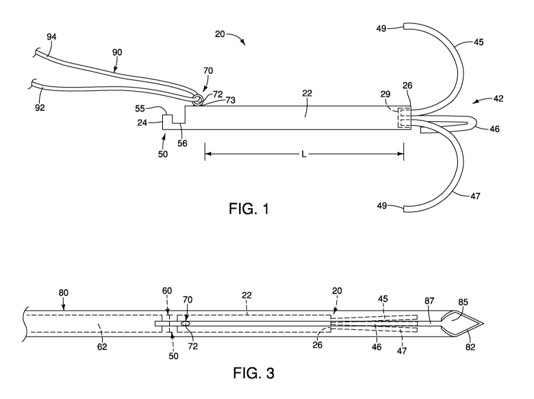
[0013] FIG. 1 is a side view of a tacking device.
[0014] FIG. 2 is a side-sectional view of a distal region of an insertion tool
and the tacking
device of FIG. 1.
[0015] FIG. 3 is a top view of the distal region of the insertion tool and the
tacking device of
FIG. 2.
[0016] FIG. 4 is a side-sectional view of the distal region of an insertion
device housing the
insertion tool and the tacking device of FIGS. 1-3.
[0017] FIGS. 5-10 illustrate one exemplary method of use of the tacking device
of FIGS. 1-4,
with tissue shown from a side-sectional view, and device components shown from
a side
view for illustrative purposes.
3
CA 02746213 2011-06-07
WO 2010/077608 PCT/US2009/066992
DETAILED DESCRIPTION OF THE PREFERRED EMBODIMENTS
[0018] In the present application, the term "proximal" refers to a direction
that is generally
towards a physician during a medical procedure, while the term "distal" refers
to a direction
that is generally towards a target site within a patient's anatomy during a
medical procedure.
[0019] Referring now to FIG. 1, a first embodiment of a tacking device 20 is
shown. In this
embodiment, the tacking device 20 comprises a main body 22 having a proximal
end 24 and
a distal end 26. The tacking device 20 further comprises a distal deployment
mechanism 42,
which comprises three distal deployable members 45-47. The distal deployable
members 45-
47 extend distally from the distal end 26 of the main body 22, as shown in
FIG. 1. The distal
deployable members 45-47 each may be integrally formed with the main body 22
or formed
separately and coupled to the main body 22. In the latter embodiment, a recess
29 may be
formed in the distal end 26 of the main body 22, and proximal regions of the
three distal
deployable members 45-47 may be secured within the recess 29 of the main body
22 using an
adhesive, frictional fit, mechanical device or other suitable mechanism.
Alternatively, the
recess 29 may be omitted and the distal deployable members 45-47 may be
coupled or
adhered to an exterior surface of the main body 22 near the distal end 26.
[0020] While three total distal deployable members 45-47 are depicted, it will
be apparent
that greater or fewer deployable members may be employed. Moreover, the distal
deployable
members 45-47 may comprise any shape suitable for engaging, penetrating and/or
abutting
tissue, for purposes explained further below, and need not necessarily assume
the expanded
shape depicted in FIG. 1.
[0021] The main body 22 may comprise any suitable shape and material. Solely
by way of
example, the main body 22 may comprise stainless steel or a biocompatible
plastic. The
main body 22 may be cylindrically-shaped, as depicted in FIG. 1, which may
facilitate
insertion through a lumen of an insertion tool 80, as explained below.
[0022] The distal deployable members 45-47 each comprise a contracted delivery
configuration, as shown in FIGS. 2-3, and further comprise an expanded
deployed
configuration, as shown in FIG. 1. In one embodiment, each of the distal
deployable
members 45-47 comprises a hook-shaped configuration in the expanded state. For
example,
the distal deployable members 45-47 may comprise a curvature of about 90 to
about 360
degrees in the expanded state, and more preferably about 180 degrees, as shown
in FIG. 1.
4
CA 02746213 2011-06-07
WO 2010/077608 PCT/US2009/066992
Where the distal deployable members 45-47 "retroflex" and comprises a
curvature of about
180 degrees, the end regions 49 of the distal deployable members 45-47 are
oriented
substantially parallel to the main body 22. Moreover, the end regions 49 may
be radially
spaced apart from one another in the expanded state, as shown in FIG. 1. In
this
configuration, the end regions 49 may be well-suited for engaging, grasping,
piercing and/or
abutting tissue. In the embodiments depicted herein, the end regions 49
comprise blunt tips,
but alternatively may comprise sharpened tips to facilitate piercing of
tissue.
[0023] The distal deployable members 45-47 may comprise a shape-memory
material, such
as a nickel-titanium alloy (nitinol). If a shape-memory material such as
nitinol is employed,
the distal deployable members 45-47 may be manufactured such that they can
assume the
preconfigured expanded state shown in FIG. 1 upon application of a certain
cold or hot
medium. More specifically, a shape-memory material may undergo a substantially
reversible
phase transformation that allows it to "remember" and return to a previous
shape or
configuration. For example, in the case of nitinol, a transformation between
an austenitic
phase and a martensitic phase may occur by cooling and/or heating (shape
memory effect) or
by isothermally applying and/or removing stress (superelastic effect).
Austenite is
characteristically the stronger phase and martensite is the more easily
deformable phase.
[0024] In an example of the shape-memory effect, a nickel-titanium alloy
having an initial
configuration in the austenitic phase may be cooled below a transformation
temperature (Mf)
to the martensitic phase and then deformed to a second configuration. Upon
heating to
another transformation temperature (Af), the material may spontaneously return
to its initial,
predetermined configuration, as shown in FIG. 1. Generally, the memory effect
is one-way,
which means that the spontaneous change from one configuration to another
occurs only
upon heating. However, it is possible to obtain a two-way shape memory effect,
in which a
shape memory material spontaneously changes shape upon cooling as well as upon
heating.
[0025] Alternatively, the distal deployable members 45-47 may be made from
other metals
and alloys that are biased, such that they may be restrained by the insertion
tool 80 prior to
deployment, but are inclined to return to their relaxed, expanded
configuration upon
deployment. Solely by way of example, the distal deployable members 45-47 may
comprise
other materials such as stainless steel, cobalt-chrome alloys, amorphous
metals, tantalum,
platinum, gold and titanium. The distal deployable members 45-47 also may be
made from
non-metallic materials, such as thermoplastics and other polymers. As noted
above, the distal
5
CA 02746213 2011-06-07
WO 2010/077608 PCT/US2009/066992
deployable members 45-47 may comprise any shape suitable for engaging,
penetrating and/or
abutting tissue, for purposes explained further below, and need not
necessarily assume the
curved shape depicted in FIG. 1.
[0026] Referring still to FIG. 1, the tacking device 20 further comprises a
first retainer 50
disposed at the proximal end 24 of the main body 22. As explained further
below, the first
retainer 50 may be used in conjunction with a second retainer 60 that may be
advanced or
retracted by a physician. In use, the first retainer 50 is configured to be
proximally retracted,
via the second retainer 60, after the distal deployable members 45-47 have
been at least
partially deployed at a preliminary location within tissue, thereby allowing
for a controlled
release of the tacking device 20 and repositioning of the distal deployable
members 45-47 at
a final location., as explained further in FIGS. 5-10 below.
[0027] Still further, the tacking device 20 comprises a loop member 70, which
preferably is
disposed near the proximal end 24 of the main body 22, for example, at a
location just distal
to the first retainer 50. The loop member 70 may be formed integrally with the
main body
22, or alternatively, may be secured to the main body 22 using any suitable
technique, such as
a solder or weld 73. The loop member 70 comprises an aperture 72, which is
sized to receive
a suture 90 having first and second ends 92 and 94, as shown in FIG. 1. In
use, the suture 90
is disposed through the aperture 72 of the loop member 70 and may be actuated
to
correspondingly actuate a portion of the tacking device 20. For example, as
described further
with respect to FIG. 10 below, the suture 90 may be actuated in a purse-string
fashion to
facilitate closure of an opening in tissue when at least two tacking devices
are deployed to at
least partially surround an opening in the tissue.
[0028] The dimension of the tacking device 20 may be tailored based on a
particular surgical
procedure, a particular patient's anatomy and/or other factors. However, for
illustrative
purposes, in a visceral wall closure operation as explained in FIGS. 5-10
below, the
longitudinal length of the main body 22 may range from about 2mm to about
15mm, the
straightened (delivery or non-curved) length of the distal deployable members
45-47 may
range from about 5mm to about 50mm, the outer diameter of the main body 22 may
range
from about 0.3mm to about 2.0mm, and the outer diameter of the distal
deployable member
45-47 may range from about 0.1mm to about 1.0mm. Further, a longitudinal
distance L
between the end regions 49 of the tacking device 20 and the loop member 70 may
be selected
to cause the loop member 70 to be positioned proximal to a mucosal layer of
tissue when the
6
CA 02746213 2011-06-07
WO 2010/077608 PCT/US2009/066992
distal deployable members 45-47 are engaged with the tissue, as depicted in
FIGS. 9-10
below, and may range from about 2mm to about 12mm. Such dimensions are
provided for
reference purposes only and are not intended to be limiting.
[0029] Referring now to FIGS. 2-3, one or more tacking devices 20 may be
delivered to a
target site in a patient's anatomy using an insertion tool 80. In FIGS. 2-3,
the tacking device
20 is shown in the contracted state, whereby the distal deployable members 45-
47 may
comprise a substantially longitudinally-oriented profile, i.e., oriented along
a longitudinal
axis of the insertion tool 80.
[0030] The insertion tool 80 may comprise a needle-like body having a
sharpened distal tip
82 and a hollow lumen 85. If the insertion tool comprises a needle-like body,
it may be
manufactured from stainless steel or any other suitable material, and may
comprise an
endoscopic ultrasound (EUS), or echogenic, needle. Solely by way of example, a
needle-like
insertion tool may comprise the EchoTip Ultrasound Needle, or the EchoTip
Ultra
Endoscopic Ultrasound Needle, both manufactured by Cook Endoscopy of Winston-
Salem,
N.C. Further details of a suitable insertion tool comprising a needle-like
body are described
in further detail in U.S. Provisional Patent Application Serial No.
12/428,226, filed April 22,
2009 (hereinafter "the '226 application"), which is hereby incorporated by
reference in its
entirety.
[0031] Further, the insertion tool 80 may comprise one or more markers
disposed near the
distal tip 82 and configured to be visualized under fluoroscopy of other
imaging techniques to
facilitate location of the distal tip 82. In the event the insertion tool is
intended to penetrate
tissue, the markers may help a physician determine how far the insertion tool
80 has
penetrated into the tissue. Optionally, if the insertion tool comprises a
needle-like body
having a sharpened distal tip 82, a sheath member having an inner diameter
larger than an
outer diameter of the insertion tool 80 may be longitudinally advanced over
the insertion tool
80, e.g., to cover the sharpened tip and optionally provide a blunt tip for
pushing against
tissue, as explained further in the '226 application.
[0032] In an alternative embodiment, the insertion tool 80 may comprise a
catheter-like body
having a substantially blunt distal tip. If the insertion tool 80 comprises a
catheter-like body
having a blunt distal tip, the end regions 49 of the distal deployable members
45-47 may be
sharpened to penetrate tissue in lieu of penetration by the insertion tool 80.
7
CA 02746213 2011-06-07
WO 2010/077608 PCT/US2009/066992
[0033] Referring still to FIGS. 2-3, the hollow lumen 85 of the insertion tool
80 may
comprise an inner diameter that is larger than an outer diameter of the
tacking device 20.
Therefore, the tacking device 20 may be loaded into the hollow lumen 54 in a
delivery
configuration, whereby the distal deployable members 45-47 are in the
contracted state, as
shown in FIGS. 2-3.
[0034] The insertion tool 80 may comprise a longitudinal slit 87 formed
therein, preferably
beginning at the distal tip 82 and extending in a proximal direction. The slit
87 may
terminate at a location proximal to where the loop member 70 is positioned
during delivery of
the tacking device 20, as depicted in FIGS. 2-3. The slit 87 preferably is
dimensioned to
receive at least a portion of the loop member 70 and the suture 90 that is
disposed through the
loop member 70. In use, when the tacking device 20 is advanced longitudinally
with respect
to the insertion tool 80, the loop member 70 may move longitudinally within
the slit 87.
[0035] As noted above, the first retainer 50 may be used in conjunction with a
second
retainer 60 that may be manipulated by a physician. The second retainer 60 may
formed
integral with or coupled to an actuating wire 62, which extends proximally and
may be
manipulated by a physician. In use, the first retainer 50 is configured to be
distally advanced,
via the actuating wire 62 and the second retainer 60, to at least partially
deploy the tacking
device 20 at a preliminary location. If it becomes desirable to reposition the
partially or fully
deployed tacking device 20, the actuating wire 62 and the second retainer 60
then may be
proximally retracted, thereby proximally retracting the engaged first retainer
50 and
associated tacking device 20, and allowing for repositioning of the distal
deployable members
45-47 at a subsequent location. When a desired final location is achieved, the
first retainer 50
is configured to be disengaged from the second retainer 60, leaving only the
tacking device
20 inside the body, as explained in FIG. 9 below.
[0036] Various types of complementary first and second retainers 50 and 60 may
be used to
facilitate controlled release of the tacking device 20 in accordance with the
present
embodiments. Suitable complementary first and second retainers 50 and 60 are
described in
commonly-assigned U.S. Patent Application Serial No. 11/807,827, filed May 30,
2007
(hereinafter "the '827 application"), which is hereby incorporated by
reference in its entirety.
The first and second retainers 50 and 60 shown in the present application
therefore are one of
multiple possible types of retaining mechanisms for controlled release of the
tacking device
20.
8
CA 02746213 2011-06-07
WO 2010/077608 PCT/US2009/066992
[0037] The second retainer 60 is complementary to the first retainer 50 so
that the first and
second retainers 50 and 60 can be matingly joined. Accordingly, the first
retainer 50 has a
knob 55 disposed proximal to a notch 56, as shown in FIGS. 1-2. In a
symmetrical manner,
the second retainer 60 has a knob 65 disposed distal to a notch 66, as shown
in FIG. 2. The
knobs 55 and 65 may approximate the shape of a half-cylinder having a flat
surface, as
depicted in FIGS. 2-3, or alternatively may comprises a rounded configuration,
as described
further in the '827 application.
[0038] The first and second retainers 50 and 60 are joined with each other by
locating the
knob 55 of first retainer 50 within the notch 66 of the second retainer 60,
and by locating the
knob 65 of the second retainer 60 within the notch 56 of the first retainer
50. When joined,
the first and second retainers 50 and 60 form a substantially continuous
cylinder shape having
substantially the same outer diameter, as shown in FIGS. 2-3. The outer
diameter of the first
and second retainers 50 and 60, when mated, preferably is slightly less than
an inner diameter
of the insertion tool 80, and further preferably is substantially identical to
the outer diameter
of the main body 22, as depicted in FIGS. 2-3.
[0039] It should be noted that although first retainer 50 matingly joins with
second retainer
60, they will not retain a joined position unless they are held together.
Since the insertion
tool 80 comprises an inner diameter that is slightly larger than the mated
first and second
retainers 50 and 60, the insertion tool 80 therefore holds and maintains the
first and second
retainers 50 and 60 in a mating position, as long as the insertion tool 80
covers both the
mating first and second retainers 50 and 60, as shown in FIGS. 2-3.
[0040] The tacking device 20 may be loaded into the insertion tool 80 outside
of the patient's
body. In a first step, the actuating wire 62 may be loaded into the insertion
tool 80 such that
the second retainer 60 extends just distal to the distal tip 82 of the
insertion tool 80. The
tacking device 20 is provided and the first retainer 50 is matingly joined
with the second
retainer 60, as described above. The mating first and second retainers 50 and
60 then are
loaded through the distal tip 82 of the insertion tool 80 and advanced in a
proximal direction.
The remainder of the tacking device 20 then is advanced proximally into the
insertion tool 80,
with the loop member 70 being aligned with the slit 87, until the distal
deployable members
45-47 are contracted as shown in FIGS. 2-3. In this state, the insertion tool
80 may be
introduced into a body cavity via a working lumen of an insertion device, such
as an
endoscope, as explained further below.
9
CA 02746213 2011-06-07
WO 2010/077608 PCT/US2009/066992
[0041] Referring now to FIG. 4, an insertion device 110 suitable for
delivering the insertion
tool 80 and one or more tacking devices 20 is shown. The insertion device 110
may comprise
an endoscope having proximal and distal ends, and a working lumen 115 disposed
therebetween. For illustrative purposes, the optical components of the
endoscope are not
shown in the side-sectional view of FIG. 4. However, if an endoscope is
employed, it will be
understood that the endoscope may comprise optical components, such as fiber
optic
elements, to facilitate visualization of objects distal to, or to the side of,
the endoscope.
[0042] As shown in FIG. 4, the working lumen 115 of the insertion device 110
comprises an
inner diameter that is larger than an outer diameter of the insertion tool 80,
thereby permitting
proximal and distal advancement of the insertion tool 80 with respect to the
insertion device
110. As depicted, the loop member 70 may extend through the slit 87 of the
insertion tool 80
and into the working lumen 115 of the insertion device 110. The suture 90 is
looped through
the loop member 70, such that the first and second ends 92 and 94 of the
suture 90 extend
through the working lumen 115 adjacent to the insertion tool 80, as depicted
in FIG. 4.
[0043] Referring now to FIGS. 5-10, one exemplary method of use of the tacking
device 20
and the insertion tool 80 is described. In FIGS. 5-10, multiple tacking
devices are used to
facilitate closure of an opening 105 in tissue 104. The tissue 104 comprises a
mucosal layer
107 and a serosal layer 108. By way of example, the opening 105 may be formed
during a
translumenal procedure, whereby the tissue 104 may comprise tissue of the
stomach, small or
large intestines, or another bodily passage.
[0044] In order to facilitate closure of the opening 105, a plurality of
tacking devices 20 are
disposed at least partially through the tissue 104 at one or more locations in
the vicinity of the
opening 105. Preferably, multiple tacking devices 20 at least partially
surround the perimeter
of the opening 105. In the embodiment of FIGS. 5-10, a first tacking device
20a is disposed
on one side of the opening 105, and a second tacking device 20b is disposed on
a
substantially opposing side of the opening 105.
[0045] In a first step, the insertion device 110 of FIG. 4 may be advanced
through a bodily
lumen such as the alimentary canal to a position proximate the target tissue
104. Preferably,
this is accomplished with the assistance of an endoscope or laparoscope,
although the tacking
device could also be used in open surgery. The insertion tool 80, with the
first tacking device
20a loaded therein in the contacted state, is positioned within the working
lumen 115 of the
insertion device 110. At this time, the second retainer 60 is coupled to the
first retainer 50, as
CA 02746213 2011-06-07
WO 2010/077608 PCT/US2009/066992
explained in FIGS. 2-4 above. Further, the suture 90 is coupled to the first
tacking device 20a
by being looped through the loop member 70, which extends through the slit 87
in the
insertion tool 80, as shown in FIG. 4.
[0046] Under visualization using the insertion device 110 and/or another
suitable imaging
modality, the insertion tool 80 may be advanced in a distal direction with
respect to the
insertion device 110. The insertion tool 80 may pierce partially through the
tissue 104 at a
preliminary location 117 around the perimeter of the opening 105, as shown in
FIG. 5. The
sharpened distal tip 82 of the insertion tool 80 may be advanced to a
predetermined depth into
the tissue 104, while the first tacking device 20a is in the contracted
delivery state within the
hollow lumen 85. As noted above, markers on the insertion tool 80 may
facilitate in
determining how far the insertion tool 80 has penetrated into the tissue 104.
[0047] Referring to FIG. 6, in a next step the physician may at least
partially deploy the first
tacking device 20a at the preliminary location 117. In one technique, the
actuating wire 62
and associated second retainer 60 may be advanced in a distal direction with
respect to the
insertion tool 80. Since the second retainer 60 is still coupled to the first
retainer 50, the
distal movement of the actuating wire 62 correspondingly moved the first
tacking device 20a
in a distal direction with respect to the insertion tool 80. As shown in FIG.
6, when the distal
deployable members 45-47 are no longer radially constrained by the insertion
tool 80, they
may assume their predetermined expanded configurations in which they may
engage,
penetrate and/or abut the tissue 104. It should be noted that the loop member
70 may slide
distally within the slit 87 of the insertion tool 80 as the first tacking
device 20 is distally
advanced. Further, it should be noted that in an alternate deployment
technique, the actuating
wire 62 and associated second retainer 60 may be held steady, and the
insertion tool 80 may
be proximally retracted with respect to the first tacking device 20a to at
least partially deploy
the distal deployable members 45-47.
[0048] In accordance with one aspect, the physician may determine that the
first tacking
device 20a is desired to be repositioned. For example, the physician may
realize that the
main body 22 and/or the distal deployable members 45-47 have been deployed too
close, or
too far, from the opening 105 in the tissue 104, or that the distal deployable
members 45-47
have been deployed in an undesirable orientation. Since the first retainer 50
is still engaged
with the second retainer 60 within the insertion tool 80, as described in
FIGS. 2-4, the
physician may "recapture" and subsequently reposition the first tacking device
20a. In
11
CA 02746213 2011-06-07
WO 2010/077608 PCT/US2009/066992
particular, the physician may proximally retract the actuating wire 62, which
retracts the
second retainer 60, the first retainer 50 coupled thereto, and the associated
first tacking device
20a. When the first tacking device 20a is proximally retracted with respect to
the insertion
tool 80, the distal deployable members 45-47 may be brought back into the
lumen 85 of the
insertion tool 80 and assume the contracted state, shown in FIGS. 2-4. In an
alternate
technique, the physician may distally advance the insertion tool 80, while the
actuating wire
62 is held steady, to advance the insertion tool 80 over the distal deployable
members 45-47.
When the distal deployable members 45-47 are within the confines of the hollow
lumen 85,
the physician then may proximally retract the insertion tool 80 and first
tacking device 20a, in
tandem, so that the insertion tool 80 and the first tacking device 20a are no
longer engaged
with the tissue 104.
[0049] Preferably, the physician recaptures the distal deployable members 45-
47 in the same
manner in which they were deployed, i.e., either the insertion tool 80 is
advanced and
retracted while the retainers are always held steady, or vice versa. By
deploying and
recapturing in the same manner, the tacking device may enter and exit the
tissue in
substantially the same path, which may reduce trauma to the tissue. It should
also be noted
that if a sheath member is employed and configured to be longitudinally
advanced over the
insertion tool 80, e.g., to cover the sharpened tip, the sheath member may
also be used to
recapture the tacking device by being distally advanced relative to both the
insertion tool 80
and the partially deployed tacking device. Preferably, the distal deployable
members 45-47
comprise substantially smooth outer surfaces to prevent snagging on the tissue
74 when
moved from the expanded to contracted states, and more preferably, the distal
deployable
members 45-47 are free of barb-like elements.
[0050] Referring now to FIGS. 7-8, in a next step, the physician may
reposition the insertion
tool 80 at another location within the tissue 104, such as a first final
location 118. The
insertion tool 80 may pierce the tissue 104 at the first final location 118,
as shown in FIG. 7,
and the first tacking device 20a may be distally advanced with respect to the
insertion tool 80
to cause the distal deployable members 45-47 to engage the tissue 104, as
shown in FIG. 8
and described above.
[0051] Referring now to FIG. 9, if the deployment of the first tacking device
20a is deemed
acceptable, the physician then may release the first tacking device 20a.
Specifically, the
insertion tool 80 may be retracted proximally with respect to the first
tacking device 20a,
12
CA 02746213 2011-06-07
WO 2010/077608 PCT/US2009/066992
while the actuating wire 62 is held steady, to expose the junction between the
first and second
retainers 50 and 60. When the insertion tool 80 passes the first and second
retainers 50 and
60, they detach and release from each other. The first tacking device 20a is
left inside the
body, with the distal deployable members 45-47 engaging the tissue 104. It
should be noted
that the loop member 70 of the first tacking device 20 preferably is disposed
proximal to the
mucosal layer 107 of the tissue 104, as shown in FIG. 9. The suture 90 remains
looped
through the loop member 70, with the first and second ends 92 and 94 of the
suture 90
extending through the working lumen 115 of the insertion device 110 and
outside of the
body.
[0052] In a next step, the insertion tool 80 may be proximally retracted until
the distal tip 82
is outside of the insertion device 110 and the patient's body. A second
tacking device 20b
then may be loaded into the insertion tool 80, preferably in the same manner
described above.
In particular, the first and second retainers 50 and 60 are matingly joined,
then the tacking
device 20b is loaded into the insertion tool 80 in a proximal to distal
direction until the distal
deployable members 45-47 are contracted as shown in FIGS. 2-3. At this time,
the loop
member 70 of the second tacking device 20b is aligned with the slit 87 of the
insertion tool
80. One free end of the suture 90 then may be looped through the loop member
70 of the
second tacking device 20b. The insertion tool 80 then may be advanced through
the working
lumen 115 of the insertion device 110, while the suture 90 is disposed
partially within the
working lumen 115 with the first and second ends 92 and 94 of the suture 90
configured to be
manipulated by a physician.
[0053] Referring to FIG. 10, the second tacking device 20b may be deployed at
a second
final location 119 in the tissue 104 in the manner described above for the
first tacking device
20b. Notably, the physician may recapture and reposition the tacking device
20b after the
distal deployable members 45-47 have been at least partially deployed, so long
as the first
and second retainers 50 and 60 remain joined. Once the final positioning is
acceptable, the
physician may proximally retract the insertion tool 80 with respect to the
tacking device 20b
to expose the junction between the first and second retainers 50 and 60,
thereby detaching the
retainers and leaving the second tacking device 20b at the second final
location 119. It
should be noted that the suture 90 remains looped through both the loop
members 70 of the
first and second tacking device 20a and 20b, as shown in FIG. 10, with the
free ends 92 and
94 extending outside of the body for manipulation by a physician. In this
manner, any
13
CA 02746213 2011-06-07
WO 2010/077608 PCT/US2009/066992
number of subsequent tacking device 20 may be inserted and deployed to at
least partially
surround the perimeter of the opening 105.
[0054] The two free ends 92 and 94 of the suture 90 may be independently
tensioned to
facilitate closure of the opening 105. When the ends 92 and 94 are tensioned,
it reduces the
distance between the tacking devices and compresses the tissue 104 around the
perforation
105. Preferably, multiple tacking devices having loop members 70 are
sequentially
positioned to at least partially surround the perforation 105 in a semi-
annular or annular
shape. The suture ends 92 and 94 may be secured to maintain the compression of
the tissue
104 using any suitable technique such as by forming a knot or using clamps,
rivets and the
like.
[0055] Further, in lieu of the loop members 70 described herein, other
mechanisms for
engaging and/or retaining sutures may be integrally formed with the tacking
device 20 or
externally attached thereto. Solely by way of example, such suture retaining
mechanisms are
explained in pending U.S. patent application Serial No. 11/946,565, filed
November 28,
2007, the entire disclosure of which is hereby incorporated by reference in
its entirety.
[0056] Various types of sutures 90 may be used in conjunction with the
embodiments herein.
For example, synthetic sutures may be made from polypropylene, nylon,
polyamide,
polyethylene, and polyesters such as polyethylene terephthalate. These
materials may be
used as monofilament suture strands, or as multifilament strands in a braided,
twisted or other
multifilament construction. However, the tacking device 20 also could be used
to tack down
a graft or other implantable member, without the use of a suture system.
[0057] While the examples shown above have illustratively described tacking
devices that
may be useful for closing openings in bodily walls during translumenal
procedures, the
tacking devices 20 also may be used in other procedures. For example, the
tacking devices
20 may be used for coupling a graft member to tissue to cover and seal a
perforation, such as
a hernia, and may be used to secure a graft member to tissue for
reconstructing local tissue, or
for treating anatomoses, and the like.
[0058] Further, the tacking device 20 may be used to grasp or manipulate
tissue 104, and
then be withdrawn from the body. For example, after the distal deployable
members 45-47
have been deployed into the tissue 104 as shown in FIG. 6 above, a physician
may
manipulate the tissue 104 via the engaged distal deployable members 45-47,
e.g., in a manner
similar to a forceps, except that the manipulation occurs from within the
tissue 104 as
14
CA 02746213 2011-06-07
WO 2010/077608 PCT/US2009/066992
opposed to externally from the mucosal layer 107 only. After the desired
manipulation has
occurred, the distal deployable members 45-47 may be removed from engagement
with the
tissue 104, as set forth above, and subsequently permanently deployed or
removed from the
body.
[0059] In further alternative embodiments, the apparatus and methods described
herein may
be used for engaging a layer of material, and are not restricted to methods
for treatment of a
human or animal body by surgery or therapy. For example, the first tacking
device may be
inserted to a position proximate a layer of material with the distal
deployable members in the
contracted states. The distal deployable members may be at least partially
expanded to
engage the layer of material at a preliminary location. A first retainer
disposed at the
proximal end of the main body may be proximally retracted to thereby
proximally retract and
contract the distal deployable members. The first tacking device may be
repositioned at a
first final location, and the distal deployable members may be deployed to
engage the layer of
material in the expanded state at the first final location, as generally
described above.
[0060] While various embodiments of the invention have been described, the
invention is
not to be restricted except in light of the attached claims and their
equivalents. Moreover, the
advantages described herein are not necessarily the only advantages of the
invention and it is
not necessarily expected that every embodiment of the invention will achieve
all of the
advantages described.