Note: Descriptions are shown in the official language in which they were submitted.
81644476
-1-.
METHOD FOR THREADING A MATERIAL LAYER
=THROUGH A MACHINE PATH
Related Applications
Thia application claims the benefit of pending
U.S. provisional patent application Serial No. 61/400,318
filed 26 July 2010.
Background of the Invention
The invention disclosed herein relates to
apparatus = and methods for waste reduction and
improvements to the quality and production in web
processing operations, such as diaper manufacturing.
While the description provided relates to diaper
= manufacturing, the Apparatus and method are easily
adaptable to other applications.
= Generally, diapers comprise an
absorbent
insert or patch and a chassis, which, when the diaper is
worn, supports the inert proximate a wearer's body.
Additionally, diapers may include other various patches,
such as tape tab patches, reusable fasteners and the
like. The raw materials used in forming a representative
CA 2746383 2017-06-20
CA 02746383 2011-07-14
Atty. Docket No.: 1047.19948-CIP CA
- 2 -
insert are typically cellulose pulp, tissue paper, poly,
nonwoven web, acquisition, and elastic, although
application specific materials are sometimes utilized.
Usually, most of the insert raw materials are provided in
roll form, and unwound and applied in assembly line
fashion.
In the creation of a diaper, multiple roll-fed
web processes are typically utilized. To create an
absorbent insert, the cellulose pulp is unwound from the
provided raw material roll and pulverized by a pulp mill.
Discrete pulp cores are formed by a core forming assembly
and placed on a continuous tissue web. Optionally, super-
absorbent powder may be added to the pulp core. The
tissue web is wrapped around the pulp core. The wrapped
core is debulked by proceeding through a calender unit,
which at least partially compresses the core, thereby
increasing its density and structural integrity. After
debulking, the tissue-wrapped core is passed through a
segregation or knife unit, where individual wrapped cores
are cut. The cut cores are conveyed, at the proper pitch,
or spacing, to a boundary compression unit.
While the insert cores are being formed, other
insert components are being prepared to be presented to
the boundary compression unit. For instance, the poly
sheet is prepared to receive a cut core. Like the
cellulose pulp, poly sheet material is usually provided
in roll form. The poly sheet is fed through a splicer and
accumulator, coated with an adhesive in a predetermined
pattern, and then presented to the boundary compression
unit. In addition to the poly sheet, which may form the
bottom of the insert, a two-ply top sheet may also be
formed in parallel to the core formation. Representative
plies are an acquisition web material and a nonwoven web
material, both of which are fed from material rolls,
through a splicer and accumulator. The plies are coated
CA 02746383 2011-07-14
Atty. Docket No.: 1047.19948-CIP CA
- 3 -
with adhesive, adhered together, cut to size, and
presented to the boundary compression unit. Therefore, at
the boundary compression unit, three components are
provided for assembly: the poly bottom sheet, the core,
and the two-ply top sheet.
A representative boundary compression unit
includes a die roller and a platen roller. When all three
insert components are provided to the boundary
compression unit, the nip of the rollers properly
compresses the boundary of the insert. Thus, provided at
the output of the boundary compression unit is a string
of interconnected diaper inserts. The diaper inserts are
then separated by an insert knife assembly and properly
oriented. At this point, the completed insert is ready
for placement on a diaper chassis.
A representative diaper chassis comprises
nonwoven web material and support structure. The diaper
support structure is generally elastic and may include
leg elastic, waistband elastic and belly band elastic.
The support structure is usually sandwiched between
layers of the nonwoven web material, which is fed from
material rolls, through splicers and accumulators.
The present invention relates to disposable
hygiene products and to methods and apparatuses for
processing components of disposable hygiene products.
More specifically, the invention relates to manufacturing
a stretchable breathable laminate that is bonded at a
plurality of bond sites.
Elastic laminates can be formed of a layer of
stretched elastic between two non-stretched layers of
non-woven material. Once the stretched elastic layer is
bonded with the non-stretched non-woven, a stretch engine
is formed once the elastic material is allowed to relax,
forming a laminate that can be stretched in the machine
direction.
CA 02746383 2011-07-14
1
Atty. Docket No.: 1047.19948-CIP CA
- 4 -
During construction of such laminates, defects
in the elastic material supplied to the process can
result in snapped or otherwise unacceptable elastic
introduced to the system. If such unacceptable elastic
is introduced into the laminate, the manufacturing
process can require slowing or stoppage in order for
properly produced laminate to be re-introduced into the
process. One aspect of the present invention relates to
an automated method and apparatus to first detect such
defects, and to automatically re-thread the elastic
material through stretch rollers and continue with the
processing sequence using acceptable elastic material
resulting in an acceptable formed laminate.
Such automation results in less manual
threading and re-threading, and less system downtime and
scrapped product (resulting from unacceptable elastic
forming unacceptable laminate).
The chassis may also be provided with several
patches, besides the absorbent insert. Representative
patches include adhesive tape tabs and resealable
closures.
The process utilizes two main carrier webs; a
nonwoven web which forms an inner liner web, and an outer
web that forms an outwardly facing layer in the finished
diaper. In a representative chassis process, the nonwoven
web is slit at a slitter station by rotary knives along
three lines, thereby forming four webs. One of the lines
is on approximately the centerline of the web and the
other two lines are parallel to and spaced a short
distance from the centerline. The effect of such slicing
is twofold; first, to separate the nonwoven web into two
inner diaper liners. One liner will become the inside of
the front of the diaper, and the second liner will become
the inside of the back of that garment. Second, two
separate, relatively narrow strips are formed that may be
CA 02746383 2011-07-14
Atty. Docket No.: 1047.19948-CIP CA
- 5 -
subsequently used to cover and entrap portions of the
leg-hole elastics. The strips can be separated physically
by an angularly disposed spreader roll and aligned
laterally with their downstream target positions on the
inner edges of the formed liners.
After the nonwoven web is sliced, an adhesive
is applied to the liners in a predetermined pattern in
preparation to receive leg-hole elastic. The leg-hole
elastic is applied to the liners and then covered with
the narrow strips previously separated from the nonwoven
web. Adhesive is applied to the outer web, which is then
combined with the assembled inner webs having elastic
thereon, thereby forming the diaper chassis. Next, after
the elastic members have been sandwiched between the
inner and outer webs, an adhesive is applied to the
chassis. The chassis is now ready to receive an insert.
To assemble the final diaper product, the
insert must be combined with the chassis. The placement
of the insert onto the chassis occurs on a placement drum
or at a patch applicator. The inserts are provided to the
chassis on the placement drum at a desired pitch or
spacing. The generally flat chassis/insert combination is
then folded so that the inner webs face each other, and
the combination is trimmed. A sealer bonds the webs at
appropriate locations prior to individual diapers being
cut from the folded and sealed webs.
Roll-fed web processes typically use splicers
and accumulators to assist in providing continuous webs
during web processing operations. A first web is fed from
a supply wheel (the expiring roll) into the manufacturing
process. As the material from the expiring roll is
depleted, it is necessary to splice the leading edge of a
second web from a standby roll to the first web on the
expiring roll in a manner that will not cause
interruption of the web supply to a web consuming or
81644476
- 6 -
utilizing device.
In a splicing system, a web accumulation
dancer system may be employed, in which an accumulator
collects a substantial length of the first web. By using
an accumulator, the material being fed into the process
can continue, yet the trailing end of the material can be
stopped or slowed for a short time interval so that it
can be spliced to leading edge of the new supply roll.
The leading portion of the expiring roll remains supplied
continuously to the web-utilizing device. The accumulator
continues to feed the web utilization process while the
expiring roll is stopped and the new web on a standby
roll can be spliced to the end of the expiring roll.
In this manner, the device has a constant web
supply being paid out from the accumulator, while the
stopped web material in the accumulator can be spliced to
the standby roll. Examples of web accumulators include
that disclosed in U.S. Patent Application Serial No.
11/110,616, which is commonly owned by the assignee of
the present application.
As in many manufacturing operations, waste
minimization is a goal in web processing applications, as
products having spliced raw materials cannot be sold to
consumers. Indeed, due to the rate at which web
processing machines run, even minimal waste can cause
inefficiencies of scale. In present systems, waste
materials are recycled. However, the act of harvesting
recyclable materials from defective product is intensive.
That is, recyclable materials are harvested only after an
identification of a reject product at or near the end of
a process. The result is that recyclable materials are
commingled, and harvesting requires the extra step of
separating waste components. Therefore, the art of web
processing would benefit from systems and methods that
CA 2746383 2017-06-20
CA 02746383 2011-07-14
Atty. Docket No.: 1047.19948-CIP CA
- 7 -
identify potentially defective product prior to product
assembly, thereby eliminating effort during recyclable
material harvesting.
Furthermore, to improve quality and production
levels by eliminating some potentially defective product,
the art of web processing would benefit from systems and
methods that ensure higher product yield and less machine
downtime.
Summary of the Invention
Provided are method and apparatus for
minimizing waste and improving quality and production in
web processing operations.
Importantly, the methods taught in the present
application are applicable not only to diapers and the
like, but in any web based operation. The waste
minimization techniques taught herein can be directed any
discrete component of a manufactured article, i.e., the
methods taught herein are not product specific. For
instance, the present methods can be applied as easily
with respect to diaper components as they can for
feminine hygiene products, as they can for face masks in
which components such as rubber bands and nose pieces are
used.
For instance, by practicing the methods of the
present invention, waste of staples and elastic bands can
be avoided during manufacture of face masks, for instance
those disclosed in U.S. Patent No. 7,131,442. One of the
objectives is simply to recognize product during
manufacture that ultimately would fail quality control
inspection, and avoid placing material on to that product
during the manufacturing processes.
As another example, the amount of adhesive
applied to certain products can be reduced by not
applying adhesive to products that have already been
determined to be defected or assigned to rejection. For
CA 02746383 2011-07-14
Atty. Docket No.: 1047.19948-CIP CA
- 8 -
instance, in U.S. Patent No. 6,521,320, adhesive
application is shown for example in Fig. 11. By assigning
or flagging product that has already been determined to
end up in a scrap or recycling pile, the adhesive flow
can be stopped or minimized.
In yet another exemplary application of the
methods of the present invention, discrete components or
raw material carried on products that have already been
determined to be defected or assigned to rejection can
also be removed and recycled prior to commingling with
other discrete components or raw material. For instance,
if an absorbent pad, such as shown at reference numeral
40 of U.S. Patent No. 6,521,320 is destined for
application to a product that has already been determined
to be defected or assigned to rejection, the absorbent
pad can be withdrawn from the product, or never
introduced in the first instance. For example, during
startup or shutdown of high speed diaper manufacturing
operations, a certain number of products is routinely
discarded into recycling. By identification of the start
up or shut down routine, avoidance of introduction of
absorbent pads can be achieved. Alternatively, during
stand-by, the absorbent pads often degrade by
accumulation of dust. By identifying which products would
bear the dust, the absorbent pads can be withdrawn from
further manufacture, and no additional components would
be applied to such a product.
In one embodiment, a method for assembling a
plurality of continuous webs is provided, including
defining first web inspection parameters and inspecting
at least one of the plurality of continuous webs to
determine whether the at least one web conforms to the
first web inspection parameters. Further, the method
involves providing a chassis web which is adapted to
receive a patch and providing a patch web from which the
CA 02746383 2011-07-14
Atty. Docket No.: 1047.19948-C1P CA
- 9 -
patch is cut. Finally, the cut patch is applied to the
chassis web if the inspected web conforms to the first
web inspection parameters. In another embodiment, the
method also includes steps of defining first patch
inspection parameters and inspecting a cut patch to
determine whether the patch conforms to the first patch
inspection parameters. While the patch inspection may
provide interesting diagnostic information related to a
web processing machine, the application of the patch may
be limited to those patches that conform to the first
patch inspection parameters.
Another embodiment of the method of the
present invention involves defining first web inspection
parameters and a product pitch. Generally in any web
process, a web is provided, which is traveling at a web
velocity. This embodiment involves inspecting the web to
determine whether the web conforms to the first web
inspection parameters and producing an inspection value
as a result of the inspecting step. This value is then
recorded once per sample time interval. The sample time
interval may be calculated by dividing the defined
product pitch by the web velocity. While the inspection
value may be as simple as a bivalent value, a more
informational multivalent value may be used.
In addition to the web process provided, an
apparatus for carrying out the process is provided. An
embodiment of the apparatus includes a continuous web
supply providing continuous web material from an upstream
position to a downstream position and a means for
providing a patch spaced from a first side of the
continuous web material. A patch applicator is provided
to alter the space between the patch providing means and
the continuous web material and a web inspection device
is positioned upstream from the patch applicator.
Additionally, a programmable controller receives an input
81644476
- 10 -
from the web inspection device and provides an output to the
patch applicator. The web processing apparatus may also include
a patch inspection device that provides an output to the
programmable controller. A patch reject conveyor may be
positioned to receive defective patches from the patch
providing means. In another embodiment of a web processing
apparatus, a product inspection device may be located
downstream from the patch applicator to provide an output to
the programmable controller. Also, a product reject conveyor
could be adapted to divert defective product as indicated by
the product inspection device.
In another embodiment, there is provided a method for
threading a material layer through a machine path, the method
comprising the steps of: providing a forwarding series of
blowing air mechanisms aimed at the material layer in a machine
direction; providing a reversing series of blowing air
mechanisms; providing a sensor, the sensor being operatively
coupled with the forwarding series of blowing air mechanisms
and operatively coupled with the reversing series of blowing
air mechanisms; detecting the material layer and determining
whether the material layer is in an acceptable or unacceptable
state; once an unacceptable state is detected, initiating the
reversing series of blowing air mechanisms to guide said
material layer in a reverse machine direction backwards through
said machine path to a predetermined location; initiating the
forwarding series of blowing air mechanisms to guide said
material layer in a machine direction forwards through said
machine path until an acceptable material state is achieved.
CA 2746383 2017-06-20
81644476
- 10a -
Brief Description of the Drawings
Fig. 1 is a schematic of a representative web
processing system;
Fig. 2A-2C are schematic representations of a web
processing system incorporating principles of the present
invention;
Fig. 3 is an elevation view of a patch inspection;
Fig. 4 is a perspective view of a patch indexer, a
patch applicator and a patch reject conveyor;
Fig. 5 is a schematic of a second embodiment of a
representative web processing system;
Fig. 6A-6C are additional schematic representations
of a web processing system incorporating principles of the
present invention.
Fig. 7 is a perspective view of a layered stretch
bond laminate, with an elastomeric layer sandwiched between two
non-elastomeric layers of material;
Fig. 8 is a cross-sectional view of the laminate
shown in Fig. 7;
Fig. 9 is a cross-sectional view of the laminate
shown in Fig. 7, with a bond-site shown;
CA 2746383 2017-06-20
CA 02746383 2011-07-14
Atty. Docket No.: 1047.19948-CIP CA
¨ 11 -
Fig. 10 is a schematic view of a two-station
apparatus for forming a stretch bonded laminate;
Fig. 11 is a schematic view of an apparatus
for forming a stretch bonded laminate, the apparatus
equipped with a series of air knives to urge an elastic
layer in the machine or the reverse machine direction
through a stretch wheel array;
Figs. 12A-C are schematic views of the
apparatus shown in Fig. 11, operating in a threading
sequence to thread the elastic layer through the stretch
wheel array;
Figs. 13-15 are schematic views of the
apparatus shown in Fig. 11, operating in an unthreading
or retreating sequence to unthread the elastic layer
through the stretch wheel array, after which the machine
will operate in the threading sequence shown in Figs.
12A-C;
Fig. 16 is a plan view of a laminate formed
during operating and threading/rethreading periods, with
the laminate having elastic in the laminate during the
operating timeframes, and no elastic in the
threading/rethreading time periods;
Figs. 17 and 18 are a drive-side view of the
stretch wheel array operating in a closely spaced
operating position (Fig. 17) and a spaced apart,
threading/unthreading position (Fig. 18).
Description of the Preferred Embodiment
Although the disclosure hereof is detailed and
exact to enable those skilled in the art to practice the
invention, the physical embodiments herein disclosed
merely exemplify the invention which may be embodied in
other specific structures. While the preferred embodiment
has been described, the details may be changed without
departing from the invention, which is defined by the
claims.
CA 02746383 2011-07-14
Atty. Docket No.: 1047.19948-CIP CA
- 12 -
It is noted that the present waste
minimization techniques and apparatus are described
herein with respect to products such as diapers, but as
previously mentioned, can be applied to a wide variety of
processes in which discrete components are applied
sequentially.
Referring to Figure 1, a web processing
operation starts with incorporating raw materials such as
paper pulp and super absorbent polymer (SAP) in a pulp
mill. The mixture is sent to a core forming drum, where
cores are formed for retaining liquids. A core can be
placed on a tissue and processed as shown. Eventually, an
additional tissue layer is formed, sandwiching the core.
The process continues through debulking, core
cutting and spacing, optionally, compression, and
application of tape and elastics. The process then
proceeds with application of outer and inner non-woven
layers, and waist elastic. The web can undergo folding,
extraction and trimming of excess material, and
application of material to tighten the diaper about the
waist. Eventually, the product is folded and packaged.
As seen on Figure I, the symbol is shown at
locations of introductions of discrete components into
the process. At these locations, inspection can take
place to determine the presence or absence of acceptable
product introduction. In addition to visual inspection,
operational characteristics such as startup/ramp-
up/shutdown operations can trigger waste minimization
techniques as will be described later.
At each of these operations shown in Fig. 1,
diagnostics can be performed to indicate whether the
product meets acceptable criteria. If so, discrete
elements, such as the core, tissue layers, elastic, etc.,
continue to be applied in a sequence such as shown in
Fig. 1. If not, no additional discrete elements need be
81644476
- 13 -
applied.
Referring now to Figures 2a-c, a web
processing operation incorporating the present invention
is shown.
Referring now to Fig. 2, an additional
schematic of processes of the present invention is shown.
As indicated, pulp rolls 200 feed raw pulp 201 into a
pulp mill 204, where the pulp is pulverized. Super
absorbent polymer is added from station 206. The SAP
laced pulp is fed onto core forming roller 208. Cores 210
from core forming roller 208 are applied to the tissue
back sheet 214 which has been introduced through tissue
back sheet feeder 212. Following debulking station 216
and core cutting and spacing station 218, an infeed of
poly layer 220, elastic layer 222 is applied to the
carrier web, in addition to non woven layer 224 and two
ply top sheet woven 226. This web then is cut at cutting
station 228 into discrete inserts 230, which are then
typically placed on a article transfer and placement
apparatus with active puck 230. This device is disclosed
in U.S. Patent Application 11/357,546, owned by the same
assignee as the present case.
The process utilizes two main carrier webs; a
nonwoven web 11 which forms an inner liner web, and a web
12 that forms an outwardly facing layer in the finished
diaper 50. In this embodiment, the nonwoven web 11 is
slit, at slitter station 15, by rotary knives 14 along
three lines. one of these lines is preferably on
approximately the centerline of web 11 and the other two
lines are parallel to and spaced a short distance from
the centerline. The effect is twofold; first, to separate
web 11 into two inner liners 20. One liner will become
the inside of the front of the diaper 50 and the second
liner will become the inside of the back of that garment.
CA 2746383 2017-06-20
CA 02746383 2011-07-14
Atty. Docket No.: 1047.19948-CIP CA
- 14 -
Second, two separate, relatively narrow strips 22 and 24
are formed which are subsequently used to cover and
entrap portions of leg-hole elastics 26. Strips 22 and 24
are separated physically by an angularly disposed
spreader roll 23 and aligned laterally with their
downstream target positions on the inner edges of the
liner webs 20.
Adhesive patterns are applied to the liner
webs 20 in target areas for the leg-hole elastics 26. A
spray gun assembly 29 of a type known in the art is
preferably used to apply the adhesive patterns. Two sets
of leg-hole, elastic strands 26 are introduced through
laydown guides 30, which reciprocate from side to side
past each other. The strands 26 are glued to the web
sections 20, their laydown patterns following a
serpentine path. Given the absence of adhesive in the
area separating the inner liners 20, for some portion of
each successive diaper product, the strands 26 each track
parallel to the inner slit edges of the web sections 20.
Laydown guides 30 then apply the strands 26, which form
leg-hole elastics as the web sections 20 are carried
along the face of a drum or roll 32. Those parts of the
elastic patterns which are near the inner slit edges of
webs 20 are then covered by the Introduction of an
adhesive lamination thereover of the strips 22 and 24 of
nonwoven web also against the drum 32.
The side-to-side excursions of the leg-hole
elastic laydown guides 30 result in arcuate segments of
elastic strands extending on each side of the web
centerline. After the nonwoven strips 22 and 24 have been
applied to cover and entrap those parts of the elastics
26 that run nearest to and parallel to the inner edges of
the webs 20, a second pair of slitter knives 34 is used
to trim away a portion of the narrow nonwoven strips 22,
24, along with that part of the inner liner webs 20 to
CA 02746383 2011-07-14
Atty. Docket No.: 1047.19948-CIP CA
- 15 -
which they are laminated. This also removes those
portions of the elastic strands 26 which are contained
within the laminations. The resultant trimmed scrap
strips 36 are removed from the process for disposal
elsewhere.
The effect of the last-described step is to
remove the cut away portions of the elastic, eliminating
its corresponding unwanted gathering effect from the
crotch region of the garments 50. The remaining portions
of the curved elastic strands create a gathering effect
around the leg openings of the finished garments 50.
Subsequent to the combining and trimming of
the inner webs 20 and the cover strips 22, 24, the
combining drum 32 carries the webs to a nip with a second
combining drum 38, where the web sections 20, with their
respective curved elastic patterns exposed, are
transferred to and laminated adhesively against the
inside face of outer liner web 12. This process entraps
the curved elastic patterns 26 between the inner liners
20 and outer web 12 thereby forming a composite web 39.
The composite web 39 is then provided with a
pattern of adhesive in preparation to receive an
absorbent insert or patch 46. The patch 46 is cut from a
provided patch web 40 by a cooperation of a cutter 41 and
an anvil surface on a vacuum roll 42 and rotated into
position for transfer to the composite web 39 by a patch
applicator 105. If the patch 46 is to be applied to the
web 39¨a determination explained more fully below¨the
patch applicator 105 forces the web 39 against the patch
46, thereby adhering the patch 46 to the web 39.
Leg-hole materials 48, if not previously
removed, are cut at a cutting station 47, thereby
removing the material 48 contained within an approximate
perimeter defined by the curved pattern of the elastics
26. The running composite chassis web 39 is folded,
CA 02746383 2011-07-14
Atty. Docket No.: 1047.19948-CIP CA
- 16 -
before or after cutting out of the leg holes,
longitudinally along its centerline, thereby generally
aligning its front waist edge with its back waist edge.
The regions 53 which are to become the side seams 54 of
the garments 50 are then welded by a sealing device 49
either ultrasonically or by heat. Note that the leg holes
are preferably cut out before this point, leaving only a
narrow zone for welding. The weld pattern is preferably
wide enough to extend into both the left side seam of one
garment and the right side seam of the adjacent garment.
The garments 50 are then separated by passing through a
cut-off knife assembly 55, which severs the web along the
transverse axis of the side seam weld 53.
In addition to the exemplary components
generally found in a web processing apparatus, the
present device and methods further include an advanced
defect detection system. An embodiment of the defect
detection system preferably comprises at least one visual
inspection station 101, but preferably a plurality of
visual inspection stations 101. Each visual inspection
station 101 may include a vision sensor, such as an In-
Sight Vision Sensor available from Cognex Corporation of
Natick, Massachusetts. Since each component part of a
product resulting from a web process has a point of
incorporation into the product, visual inspection of each
component part preferably occurs prior to the point of
incorporation. The results of the visual inspections that
occur are relayed from each visual inspection station 101
to a programmable logic controller (PLC) 103. Each visual
inspection station 101 may provide diagnostic capability
by monitoring lighting, focus and positioning.
Machine vision systems typically require
digital input/output devices and computer networks to
control other manufacturing equipment, in this case the
splicing unit.
CA 02746383 2011-07-14
Atty. Docket No.: 1047.19948-CIP CA
- 17 -
A typical machine vision system will consist
of several among the following components:
= One or more digital or analog camera (black-
and-white or colour) with suitable optics for acquiring
images
= Lighting
= Camera interface for digitizing images (widely
known as a "frame grabber")
= A processor (often a PC or embedded processor,
such as a DSP)
= Computer software to process images and detect
relevant features.
= A synchronizing sensor for part detection
(often an optical or magnetic sensor) to trigger image
acquisition and processing.
= Input/Output hardware (e.g. digital I/0) or
communication links (e.g. network connection or RS-232)
to report results
= Some form of actuators used to sort or reject
defective parts.
The sync sensor determines when a part (often
moving on a conveyor) is in position to be inspected. The
sensor triggers the camera to take a picture of the part
as it passes by the camera and often synchronizes a
lighting pulse. The lighting used to illuminate the part
is designed to highlight features of interest and obscure
or minimize the appearance of features that are not of
interest (such as shadows or reflections).
The camera's image can be captured by the
framegrabber. A framegrabber is a digitizing device
(within a smart camera or as a separate computer card)
that converts the output of the camera to digital format
(typically a two dimensional array of numbers,
corresponding to the luminous intensity level of the
corresponding point in the field of view, called pixel)
CA 02746383 2011-07-14
Atty. Docket No.: 1047.19948-CIF CA
¨ 18 -
and places the image in computer memory so that it may be
processed by the machine vision software.
The software will typically take several steps
to process an image. In this case, the image processing
will result in either detection of the indicator
material, or non-detection of the indicator material.
Commercial and open source machine vision
software packages typically include a number of different
image processing techniques such as the following:
= Pixel counting: counts the number of light or
dark pixels
= Thresholding: converts an image with gray
tones to simply black and white
= Segmentation: used to locate and/or count
parts
= Blob discovery & manipulation: inspecting an
image for discrete blobs of connected pixels (e.g. a
black hole in a grey object) as image landmarks. These
blobs frequently represent optical targets for machining,
robotic capture, or manufacturing failure.
= Recognition-by-components: extracting geons
from visual input
= Robust pattern recognition: location of an
object that may be rotated, partially hidden by another
object, or varying in size
= Barcode reading: decoding of 1D and 2D codes
designed to be read or scanned by machines
= Optical character recognition: automated
reading of text such as serial numbers
= Gauging: measurement of object dimensions in
inches or millimeters
= Edge detection: finding object edges
= Template matching: finding, matching, and/or
counting specific patterns.
In most cases, a machine vision system will
CA 02746383 2011-07-14
Atty. Docket No.: 1047.19948-CIP CA
- 19 -
use a sequential combination of these processing
techniques to perform a complete inspection. A system
that reads a barcode may also check a surface for
scratches or tampering and measure the length and width
of a machined component.
Additionally, machine downtime can be
minimized by the provision of systems and methods for
warning a machine operator of expected machine troubles
so that scheduled maintenance can occur.
The PLC 103 includes software adapted to run
several routines that may be initiated by some triggering
event, such as an automatic detection of a defined
condition or manual input by a machine operator. Some
routines are run during machine setup while other
routines are run during machine operation, while still
other routines are run during machine diagnostics at some
point during machine downtime.
The PLC 103 generally receives inputs 120 from
the visual inspection stations 101, from the various
machine components, or from manual input by a machine
operator on an operator interface, or human machine
interface (HMI) 115. Some of the inputs can also be from
stations near the pulp rolls, pulp mills, forming
rollers, or elsewhere in the system where inspection is
present.
The HMI 115 provides an interface for user
interaction with the web processing machinery and may
comprise a pressure sensitive touch screen, a keyboard, a
computer mouse, or even a wireless device providing such
an interface. The PLC 103 preferably provides controlling
outputs 121 to the patch applicator 105, the cutter 41
and vacuum roll 42, a patch reject conveyor 107 and a
product reject conveyor 109.
The input to the PLC 103 from each inspection
station 101 preferably comprises a defect indicator 111
CA 02746383 2011-07-14
Atty. Docket No.. 1047.19948-C1P CA
- 20 -
that represents a detected web defect at a position in
the process a number of patch placements from the patch
applicator 105. That is, at any given time during machine
operation, between any inspection station 101 and any
patch applicator 105 in a web process, there exists
material sufficient to produce a determinable number of
products having a patch applied thereto. Therefore, a
defect may be detected and flagged as corresponding to a
specific product location throughout the process.
In determining whether a patch should be
applied to a product by a patch applicator 105, the PLC
103 stores a product status indicator for each product in
the process, preferably for each product between the
product reject conveyor 109 and most remote visual
inspection station 101. The status indicator accumulates
defect Indicators 111 from the inspection stations 101 to
track the progress of a product through the process.
A preferred product status indicator is a byte
of digital data, with each bit reflecting the defect
indicator 111 for the tagged product from an inspection
station 101. For example, the least significant bit in
the status indicator may represent the defect indicator
for the most remote visual inspection station 101. As the
bit significance increases, so does the proximity of the
respective inspection station 101 to the product reject
conveyor 109. A byte of data would provide for the
possibility of eight inspection stations, and specific
tracking of defects at those inspection stations. To
store the product status indicator, the PLC 103
preferably includes some volatile and some nonvolatile
computer memory. The volatile memory may provide quicker
access times during machine operation, while the
nonvolatile memory could be used to store product status
indicators when the machine is paused. The minimum amount
of memory required by the PLC 103 is at least partly
CA 02746383 2011-07-14
Atty. Docket No.: 1047.19948-CIP CA
- 21 -
determined by the number of visual inspection stations
101 and the number of potential products in queue between
the first visual inspection station 101 and the product
reject conveyor 109. For example, if a web process
utilizes eight visual inspection stations 101 and two
hundred products could be in queue in any given time, a
volatile memory of at least two hundred bytes would be
required.
The visual inspection station outputs may be
sampled synchronously, or the outputs may be
asynchronously analyzed by the PLC 103. If synchronous,
the outputs may be sampled at a rate equal to the speed
of the traveling webs divided by the product pitch, or
product size. To enable use of different product sizes in
a given process, the sample timing of the inspection
station results may be varied, accordingly.
In addition to synchronous sampling of the
inspection station results, the results could be analyzed
asynchronously, which may be advantageous if various
materials are incorporated into the process at different
rates. Asynchronous analysis of the outputs, however, may
provide less visibility into the specific defects
included in a completed product.
Prior to operating or running a web process,
the machinery must be threaded with raw patch web
material. The PLC 103 may provide a software routine,
such as an automatic web threading routine, for aiding
such setup. An operator threads the patch web material 40
through the machine to the patch applicator 105. The
operator then initiates the automatic threading routine
by using the HMI 115. The EMI 115 is coupled to the PLC
103 and the PLC 103 controls the patch applicator 105,
patch cutter 41, vacuum roll 42, and patch reject
conveyor 107. A first number of patches 46 are cut by the
patch cutter 41 and culled via the patch reject conveyor
CA 02746383 2011-07-14
Atty. Docket No.. 104-7.19948-CIP CA
- 22 -
107. The culled patches 46a may be a predetermined number
from the start of the threading routine, or cut patches
46 could be inspected by a visual inspection station 101,
and culled until the patches 46 meet visual inspection
parameters 108, as seen in Figure 3.
Also, if the machine was shut down or paused
with existing patch web material loaded through the patch
cutter, but a vacuum remains drawn through the vacuum
anvil drum, the patch web material on the vacuum anvil
drum will act as an air filter. The longer the patch web
material is on the drum, the dirtier it will get. Such
soiled material may not be used in the construction of
products for sale. Therefore, the PLC 103 could provide a
software routine for clearing the vacuum anvil drum of
soiled web material. Patches that have been on the anvil
for a predetermined amount of time, and therefore may
have dust built up, are culled through the reject prior
to machine startup. Like the automatic threading routine,
a predetermined number of patches may be culled, or the
patches may be Inspected for dust build-up.
In addition to threading and anvil clearing, a
placement accuracy routine could be provided, for use on
machine startup, or when the product configuration is
changed. In a representative placement accuracy routine,
patches are placed to several startup reject products,
and relevant dimensions are taken by a visual inspection
station 101 placed downstream from the patch applicator
105. The inspection results indicate if and when the
patch placement meets specified patch placement
parameters.
During machine operation, the PLC 103, through
software algorithms, determines whether a patch 46 should
be placed by the patch applicator 105, whether the patch
46 should be culled, or whether the web 39 should be
allowed to continue to run without patch placement. A
CA 02746383 2011-07-14
Atty. Docket No.: 1047.19948-CIP CA
- 23 -
patch 46 is placed on the moving chassis web 39 only if
both the patch 46 and web 39 are in condition for
satisfactory placement.
After machine setup and threading of any
materials, the PLC 103 begins verifying status indicators
at the <application> position in memory. Generally,
during machine operation, the PLC 103 controls whether a
patch 46 is applied by a patch applicator 105. For each
product, the PLC 103 determines the action of the patch
applicator 105, the patch reject conveyor 107, and the
product reject conveyor 109. For each product presented
to a patch applicator 105, the PLC 103 issues one of the
following commands to the patch applicator 105 and patch
cutter: (1) apply patch; (2) cull patch; or (3) cull web.
The apply patch command is issued if no
component part has been flagged as defective in the
composite web 39 that is presented to the patch
applicator 105 and the patch 46, Itself, satisfies
inspection parameters. When the apply patch command is
issued, the vacuum anvil drum 42 remains relatively
stationary while the composite web 39 having a deposited
adhesive is forced by the patch applicator 105 against
the patch 46. After the patch 46 is applied, the PLC
awaits the arrival of the next patch attachment site or
product pitch.
The cull patch command is issued if a patch
46a does not meet inspection parameters. Representative
parameters can be seen in Figure 4. Culling a defective
patch 46a involves cooperation of the vacuum roll 42 and
the patch reject conveyor 107. The vacuum roll 42
preferably has a vacuum manifold that allows a release of
the vacuum draw at a certain point around the rotation
path of the roll 42. The patch reject conveyor 107 may be
a simple conveyor belt positioned just below the point
where the vacuum draw may be removed, such that gravity
CA 02746383 2011-07-14
=
Atty. Docket No.: 1047.19946-CIP CA
- 24 -
causes the unapplied patch 46a to fall onto the conveyor
107.
The cull web command is issued if any
component part of the composite web 39 is flagged as
defective.
The PLC 103 may also contain a unit
diagnostics program, which monitors parameters of the
patch on the anvil to determine the health of the cutting
knives and anvils. The unit diagnostics program involves
the use of defined patch parameters measured by a vision
inspection station and compared to expected values.
Information that is gathered by the diagnostics program
is stored and processed in a database. Where measured
parameters are approaching acceptable limits, alerts are
sent to the machine operator, indicating that potential
problems are developing. The HMI may automatically
present the Unit Diagnostics Screen for the operator to
assess the situation. Furthermore, the HMI may provide
graphics and charts to assist the operator by showing
trend data, measured data, and comparable data. Thus, an
operator is given advance notice of a problem so that any
corrections can be made during the next machine downtime.
Specifically, as the knives on the patch cutter age, the
patches tend to skew. Furthermore, the deviation between
subsequent patch cut lengths is another indicator that a
knife blade may require replacement.
In an effort to prolong machine run-time
between service and to reduce start-up rejects, an
automatic anvil adjustment program may be provided. Such
adjustment allows the anvil drum and knife roll to move
relative to one another. Startup and shutdown rejects can
result in rejections of many products. The movements are
preferably in one millimeter increments over a five
millimeter range. The adjustments are made as the machine
is running to prevent wear on a single spot as well as to
CA 02746383 2011-07-14
Atty. Docket No.: 1047.19948-CIP CA
- 25 -
minimize buildup of cut web material on the anvil. In
addition to the automatic adjustment, a manual override
adjustment may be provided for troubleshooting.
If the unit diagnostics program detects a pair
of patches that have parameters outside of acceptable
limits, which is usually caused by a catastrophic failure
of a knife or anvil, the machine operator is alerted and
the HMI preferably automatically presents the Unit
Diagnostics Screen for the operator to assess the
situation. For every knife or anvil that fails, two
patches will be affected. Therefore, if the anvil roller
can accompany eight patches, twenty-five percent of the
patches will fall out of acceptable limits. All patches
that fall out of the acceptable limits are culled by way
of the reject patch conveyor. All patches that fall
within acceptable limits will continue to be placed on a
composite web that is otherwise indicated as appropriate
for receiving a patch. After being notified of the
problem, the machine operator will observe the HMI to
verify problem. In an attempt to correct the problem, the
operator may try an electronic anvil shift, which, if
successful, will allow the process to continue. If the
electronic anvil shift does not correct the problem, the
operator will request that the machine stop. To aid in
repair or replacement of the failed knife or anvil, the
cutter and anvil drum will stop in a position allowing
easy access to the failed components. As a convenience
and to enable more efficient repair of the failed
components, a rapid change out (RCO) tool or kit could be
provided, such as a set of hex wrenches. The operator
changes the failed part and prepares the machine to
restart. The routine for automatically clearing the anvil
drum may then run, and the unit begins attaching patches
to the composite web. The alarm that first alerted the
operator of the problem is then reset, either
CA 02746383 2011-07-14
Atty. Docket No.: 1047.19948-CIP CA
- 26 -
automatically, or manually by the operator through the
use of the HMI.
There may arise a situation where multiple
anvils or knives appear to have failed. In this
situation, the operator is alerted to the problem, but no
patches are culled. Rather, a visual inspection station
downstream from the patch applicator is examined to
determine if there truly is a problem. If the problem is
verified by the placement accuracy check, the operator
shuts down the machine and proper maintenance is
performed. If an examination of the placement accuracy
inspection station does not confirm the purported
problem, the unit diagnostics program may be suspended
until it can be repaired.
Referring now to Figures 5 and 6a-c, an
additional embodiment of a representative web processing
system is shown schematically and incorporating
principles of the present invention. It is noted that
throughout the web processing, inspection systems can be
incorporated virtually anywhere, particularly at
locations of raw material input into the process.
AUTOMATED DEFECT DETECTION, ELASTIC THREADING AND RE-
THREADING
Figs. 7-15 generally describe a waste
minimization technique wherein system shutdown is
eliminated by first detecting a defect in a web component
of a disposable product, then sequentially repairing the
defect during operation of web processing machinery. The
repair can be done why the machine as a whole continues
operation, with a minimal number of products scrapped
just prior to, during and just following the repaired
portion of the web component.
Elastic laminates can be formed of a layer of
stretched elastic between two non-stretched layers of
non-woven material. Once the stretched elastic layer is
CA 02746383 2011-07-14
=
Atty. Docket No.: 1047.1994e-cip CA
- 27 -
bonded with the non-stretched non-woven, a stretch engine
is formed once the elastic material is allowed to relax,
forming a laminate that can be stretched in the machine
direction.
Referring now to Fig. 7, a perspective view of
a layered stretch bond laminate 310 is shown, with an
elastomeric layer 314 sandwiched between two non-
elastomeric layers 312a and 312b. A plurality of bond
sites 320 are provided about an elasticized area 308, and
the stretch bond laminate 310 can also be provided with a
non-elasticized area 306. The non-elasticized area 306 is
a preferred location for bonding the stretch bond
laminate 310 to other portions of a diaper product, as
the elasticized area 308 is characterized by a soft, yet
discontinuous topography due to the presence of gathered
areas in the elasticized area 308.
Referring now to Fig. 8, a cross-sectional
view of the laminate 310 shown in Fig. 7 is shown. This
view shows that the elastomeric layer 314 is sandwiched
between the non-elastomeric layers 312a and 312b. In
preferred embodiments, the elastomeric layer 314 can
comprise a single layer, or can itself comprise a series
of elastomeric materials laminated or provided together,
depending on the desired elastic characteristics of the
finished laminate 310.
Referring now to Fig. 9, a cross-sectional
view of the laminate 10 shown in Fig. 7 is shown, with
particular emphasis on a typical bond-site 320. It is
preferred that the elastomeric layer 314 be chosen with
good resistance to heat bonding or to ultrasonic bonding,
such that when the laminate 310 is processed, the
elastomeric layer 314 would behave predictably and
consistently at bond sites 320. Particularly, an
elastomeric layer 314, if itself formed of a lamination
of several layers (not shown) can be provided, the
CA 02746383 2011-07-14
Atty. Docket No.: 1047.19948-C1P CA
- 28 -
different layers of the elastomeric layer 314 can be
designed to remain somewhat intact through bond site 320.
By providing a multi-layered elastomeric layer 314, the
degree of flexibility in intended use, and control over
reaction to heat, adhesive, or ultrasonic bonding at bond
sites 320 can be more closely controlled and predicted.
As can be seen, on a microscopic level,
fibrous elements 322 of non-elastomeric layers 312a and
312b remain in bond sites 320. Further, at least a
portion of the elastomeric layer 314 can remain
commingled with fibrous elements 322 at the bond sites,
in order to provide a smooth, yet structurally stable
bond at the bond site 320.
Referring now to Fig. 10, a schematic view of
a two-station apparatus for forming the stretch bonded
laminate 310 is shown. Elastomeric layer 14 is unwound
from drum 18 and ultimately sandwiched between the non-
elastomeric layers 312a and 312b, which themselves are
being unwound from primary supply wheels 316.
The unwinding process preferably incorporates
web accumulator device 322. A common use of a web
accumulator 322 is where a web is fed from primary supply
wheel 316s and it is necessary to splice the leading edge
of the webs 312a or 312b from a standby supply wheel (not
shown) to the trailing edge of the webs 32a and 12b from
the primary supply wheel 316 in a manner that will not
cause Interruption of the web supply to a web consuming
or utilizing device.
In one known type of accumulator, the swinging
dancer arm type, there is a set of spaced apart rollers
on a swingable dancer arm cooperating with another set of
rollers on an arm that may be stationary or swingable. A
web is looped back and forth between the sets of rollers
on opposed arms in a serpentine fashion. When the
swingable arm is swung away from the other arm a
CA 02746383 2011-07-14
Atty. Docket No.: 1047.19948-CIP CA
- 29 -
substantial length of web is accumulated. During normal
running of the web the arms will be urged to their
maximum practical separation from each other to
accumulate the maximum length of web. If the infeed web
is slowed or stopped for a short time the tension in the
web urges the arms to the minimum separation position in
order to make the accumulated web available to the
machine. After infeed to the accumulator is resumed the
arms separate again and return to their original position
to accumulate and store another length of web.
In another known type of accumulator, the
linear sliding carriage type, there is a set of rollers
mounted on a movable carriage which can run linearly
toward or away from a set of corresponding rollers which
may either be stationary or similarly slidably mounted.
During normal operation of the accumulator, the two sets
of rollers will be slid to their maximum practical
separation to accumulate the maximum amount of web. If
the infeed supply to the web accumulator is slowed or
stopped, the rollers will be slid toward each other to
allow the stored web to be paid out. As the web infeed is
returned to regular operational speed the movable rollers
slide back toward the original position to accumulate
another length of web. Metering stations 332 can be
provided to analyze the speed of the infeed of the layers
312a and 312b, and to assist in determining how much
material remains on infeed rolls.
Referring still to Fig. 10, a blocking
isolation s-wrap 330 can be provided for carrying and
tensioning elastomeric layer 314. Elastomeric layer 314
enters a first cross machine direction stretch wheel 334
on one side of the web 314 in the direction of travel,
and then a second cross machine direction stretch wheel
336 on the other side of the web 14 in the direction of
travel. First, second and third stretch rollers 338, 340,
CA 02746383 2011-07-14
Atty. Docket No.: 1047.19948-CIP CA
- 30 -
and 342 are provided. In conjunction with the stretch
wheels 334 and 336, and the stretch rollers 338, 340 and
342, the elastomeric layer 314 is stretched in a
direction and tension that is user defined based on
preference of the elasticity of the lamination 310. It is
noted that stretching can be supplied to elastic layer
314 in any of the cross machine direction, the machine
direction, or a combination of both, depending on the
desired end result.
A first ultrasonic bonding station 326a
achieves breathability by joining the non-elastomeric
layer 312b with the stretched elastomeric layer 14.
Because the elastomeric layer 314 has been stretched, yet
the non-elastomeric layer 312b has not been stretched,
when the two layers are joined, the elastomeric layer 314
still will have stored the stretch.
Next, the second ultrasonic bonding station
326b bonds the pre-bonded combination of the non-
elastomeric layer 312b and elastomeric layer 314 with the
non-elastomeric layer 312a, achieving thee elastic
lamination 310. Next, the elastomeric layer 314 is taken
off of tension, which results in a gathering of the
elastomeric layer 314 to create the ripple like
appearance of the material as seen in Fig. 7.
One advantage of two station bonding is that
it offers flexibility for different anvil patterns at
each station. For instance, a chicken feet pattern at the
first station 326a, and a dot pattern anvil at the second
station 326b, results in good breathability as well as
good elastic retention forces at smaller bond sites.
Additionally, because ultrasonic bonding station 326a is
not required to penetrate three layers 312a, 314 and
312b, flexibility is offered with the degree of energy
supplied.
Alternatively, the two non-woven layers 312a
CA 02746383 2011-07-14
Atty. Docket No. 1047.19948-CIP CA
- 31 -
and 312b can be brought together with the elastomeric
layer 314 sandwiched between, and the elastomeric layer
314 can be bonded to both non-woven layers 312a and 312b
simultaneously (see Fig. 11). This has the advantage of
only requiring one bonding station.
During construction of such laminates, defects
in the elastic material 314 supplied to the process can
result in snapped or otherwise unacceptable elastic
introduced to the laminate. If such unacceptable elastic
is introduced into the laminate, the manufacturing
process can require slowing or stoppage in order for
properly produced laminate to be re-introduced into the
process and rethreaded in the manner shown in Fig. 11.
One aspect of the present invention relates to an
automated method and apparatus to first detect such
defects, and to automatically re-thread the elastic
material through stretch rollers and continue with the
processing sequence using acceptable elastic material
resulting in an acceptable formed laminate.
Such automation results in less manual
threading and re-threading, less system downtime, and and
scrapped product resulting from unacceptable elastic
forming unacceptable laminate being present in finished
product.
Air knives (shown schematically on Fig. 11)
are used in the procedure described below in order to
urge and thread the elastic layer through stretch rollers
in the machine direction as will be described later. Air
knives are also used, when necessary, to reverse defected
elastic layers in reverse machine direction back out of
the stretch rollers, and then again forward in the
machine direction through the stretch rollers in the
machine direction in order to continue the laminate
construction.
An air knife, such as a commercially available
CA 02746383 2011-07-14
Atty. Docket No.: 1047.19948-CIP CA
- 32 -
EXAIR air knife, is a tool traditionally used to blow off
liquid or debris from products as they travel on
conveyors. The knife consists
of a high intensity,
uniform sheet of laminar airflow.
A pressurized air plenum containing a series
of holes or continuous slots through which pressurized
air exits in a laminar flow pattern characterizes an air
knife. The exit air velocity then creates an impact air
velocity onto the surface of whatever object the air is
directed. This impact air velocity can range from a
gentle breeze to greater than Mach 0.6 (40,000 ft/min) to
alter the surface of a product without mechanical
contact.
Traditional uses of air knives remove liquids,
control the thickness of liquids, dry the liquid
coatings, remove foreign particles, cool product surfaces
or create a hold down force to assist in the mechanical
bonding of materials to the surface. The present use of
an air knife to transport a loose end of a web material,
such as an elastic material is novel. Several air knives
are used in succession to guide or thread the loose end
of the web material through a series of rollers or in
another targeted direction.
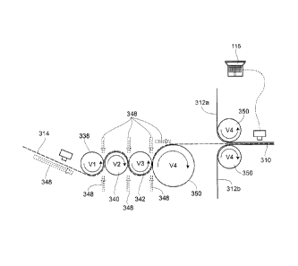
Referring now to Fig. 11, a system for
threading and re-threading the elastic layer 314 into the
stretch wheels 338, 340, 342 and 350 is shown. Stretch
wheel 338 travels at the infeed velocity V1 to mach the
speed of the incoming elastomeric layer 314. Next,
stretch wheels 340, 342 and finally 350 operate at
successively faster velocities V2, V3 and V4. V4 is
preferably the same speed as incoming non-woven layers
312a and 312b. An air knife 348 is positioned between
the incoming web of elastomeric layer 314 and the first
stretch wheel 338. A series of air
knives 348 are
provided at additional downstream locations where it is
CA 02746383 2011-07-14
Atty. . Docket No 1047.19948 -CIP CA
- 33 -
desired to steer the elastomeric layer 314.
Referring still to Fig. 11, the system is
shown in its operating condition, with incoming
elastomeric 314 already threaded under stretch wheel 338,
over stretch wheel 340, under stretch wheel 342, and
finally over stretch wheel 350. The air knives 348 are
all shown in phantom on Fig. 11, indicating that air is
not being directed through the knives 348, because under
normal operating conditions, the air is not necessary to
steer the threaded elastic 314. However, should the
elastic 314 become deformed or snap, the elastic 314 will
need to be re-threaded in the manner shown in Fig. 11 to
resume system operation.
If the elastomeric layer 314 should be
detected as being unacceptable, a threading/re-threading
sequence is initiated. Unacceptable
elastomeric 314
infeed conditions can be indicated for instance by the
first camera positioned near the infeed of elastomeric
layer 314; or missing elastomeric, as determined by the
next camera positioned after the non-woven layers have
been sandwiched about the elastomeric layer 314; or by a
pressure sensor mounted before the first stretch wheel
338.
Depending on the location and nature of the
free end of the incoming elastomeric 314, which can be
determined by additional vision sensors deployed
throughout the stretch wheel array, the elastomeric 314
might require retreatment from the stretch wheel array
(for instance if the free end of the incoming elastomeric
314 is within the stretch wheel array). Alternatively,
if the free end of the incoming elastomeric 314 is prior
to the first stretch wheel 338, retreatment will not be
necessary.
The threading/re-threading sequence involves
nearly immediate movement of the first and third stretch
CA 02746383 2011-07-14
Atty. Docket No.: 1047.19948-CIP CA
- 34 -
wheels 338 and 342 (see Figs. 17 and 18) in order to
provide adequate space for the elastomeric 314 to be
threaded through all of the stretch wheels, which, in
their operating condition, are spaced closely together.
Referring now to Figs 12A - 12C, if the free
end of the incoming elastomeric 314 is prior to the first
stretch wheel 338, retreatment will not be necessary, and
the threading sequence is shown. As can be seen, the air
knives 348 indicated in solid lines are activated with
air advancement shown in the machine direction. The
first air knife 348 (shown at left) advances the leading
edge of the incoming elastomeric 314 being paid in at its
V1 velocity, by urging the laminar air flow at the
leading edge. The second activated air knife 348 directs
more laminar air flow at the leading edge of the
elastomeric 314 to urge the leading edge of the
elastomeric 314 between the void created by the separated
stretch wheels 338 and 340. The third
activated air
knife 348 directs the leading edge of the elastomeric 314
to urge the leading edge of the elastomeric 314 between
the void created by the separated stretch wheels 340 and
342 (see Fig. 12b). The fourth activated air knife 348
directs the leading edge of the elastomeric 314 to urge
the leading edge of the elastomeric 314 between the void
created by the separated stretch wheels 342 and 350. The
last activated air knife 348 directs the leading edge of
the elastomeric 314 to urge the leading edge of the
elastomeric 314 between the non-woven layers 312a and
312b (Fig. 12c). At this point, the
first and third
stretch wheels 338 and 342 are returned to their
operating spacing, the activated air knives 348 are
deactivated, and the system is restored to its original
and properly functioning operating condition, identical
to shown in Fig. 11.
Referring now to Figs. 13-15, if the system,
CA 02746383 2011-07-14
=
Atty. Docket No.: 1047.19948-CIP CA
- 35 -
through pressure sensors or vision sensors deployed
throughout the stretch wheel array has determined that
the free end of the incoming elastomeric 314 is within
the stretch wheel array (in the illustrated embodiment,
about stretch wheel 342 in Fig. 13, a retreatment and
threading/rethreading sequence is initiated as shown in
Figs. 13-15. In this
sequence, there is also nearly
immediate movement of the first and third stretch wheels
338 and 342 as shown in Fig. 14 (see also Figs. 17 and
18) in order to provide adequate space for the
elastomeric 314 to be retreated and then threaded through
all of the stretch wheels as previously described. In
the retreatment sequence, the air knives 348 shown in
bold are activated in order to urge the leading edge of
the elastomeric 314 in the reverse machine direction,
retreating upstream of the machine direction. The
upstream facing air knives 348 remain activated until it
is detected that the leading edge of the elastomeric 314
has been removed from the stretch wheel array (see Fig.
15). When the
first camera (left side of Fig. 15)
detects the leading edge of the elastomeric 314, the
threading sequence as described in Figs. 12A-12C is
activated until the system continues in its normal
operating condition of Fig. 11.
Referring now to Fig. 16, because the
threading or the retreating/threading sequences operate
while the non-woven layers 312a and 312b are still being
introduced, there exists a gap in the introduction of the
elastomeric layer 314 between time 1, the initially
operating timeframe and time 3, the operating timeframe
after rethreading has taken place (time 2). Material
produced during time period 2, during which threading
(and possibly retreatment/threading) will not have the
elastomeric layer 314 introduced. Material produced
during time period 2 will therefore be unacceptable for
CA 02746383 2011-07-14
Atty. Docket No.: 1047.19948-CIP CA
- 36 -
use in final product. Depending on user preference, the
non-elastic laminate produced during time period 2 can
still be introduced into downstream products such as
diapers, with those products being discarded by the logic
system after final production. Alternatively, the logic
system can temporarily halt introduction of other diaper
components at times downstream matching up with when the
non-elastic laminate produced during time period 2 would
have been introduced with other components.
Referring now to Figs. 17 and 18, a drive side
view of the stretch array 338, 340, 342, and 350 is
shown. In the operating condition shown in Fig. 17, the
components are in their closely spaced configuration (see
Fig. 11). In the spaced
apart condition shown in Fig.
17, the stretch wheels 342 and 338 have been moved
linearly away from the stretch wheels 340 and 350 to
allow the spacing between stretch wheels adequate for the
air driven threading operation.
Although the foregoing description involves
the placement of an absorbent insert or patch onto a
diaper chassis, it will be apparent to those skilled in
the art that the apparatus and process could be used to
avoid unnecessary waste in the application of any sort of
patch to a moving web. Other examples of patches that may
be placed are tape tab patches and reusable fasteners.
The foregoing is considered as illustrative
only of the principles of the invention. Furthermore,
since numerous modifications and changes will readily
occur to those skilled in the art, it is not desired to
limit the invention to the exact construction and
operation shown and described. While the preferred
embodiment has been described, the details may be changed
without departing from the invention, which is defined by
the claims.