Note: Descriptions are shown in the official language in which they were submitted.
CA 02746468 2011-06-10
WO 2010/066276
PCT/EP2008/010596
- 1 -
Wellbore Machining Device
The invention relates to a wellbore machining device and in
particular a machining device for down-hole operation.
In drilling a wellbore or in oil production, there is a need for
down-hole machining tubular components, for example of a production
tubing or a casing down-hole the wellbore. To provide for a casing junction, a
window has to be milled to the casing and a pipe branching off has to be
trimmed and sealed to provide for a smooth transition. Another need is
down-hole cutting of a casing or to provide support for a lock hanger.
Another problem is cleaning and sealing leaking connections, for example of
a production tubing and up to now down-hole welding of tubular components
is a challenge.
From GB 2 129 350 A, a remotely controllable cutting apparatus
is known to cut drainage slots into a liner down in a borehole. The apparatus
comprises an elongated frame which can be clamped by hydraulic jacks to
the liner. The frame is rotatably supported by the jacks and movably guides
a cross table movably supporting a milling tool. The position of the milling
tool is monitored through a television camera.
From GB 2 353 813 A, a wellbore machining device is known
comprising a tool unit having a milling tool for cutting a hole into a casing
at a
position a junction is needed. The path on which the milling tool is moving
while milling is controlled by a mechanical template defining the shape of the
hole to be cut to the casing.
CA 02746468 2011-06-10
WO 2010/066276
PCT/EP2008/010596
- 2 -
Known prior art down-hole machining devices are often subject
to vibrations, which reduce efficiency and precision of the machining
operation and in particular accelerate wear and increase machining time. For
example, windows cut into a casing by prior art down-hole milling operation
are often rough and cause damage to sophisticated equipment which
thereafter has to be run through the window. Milling a window with such a
device will be time consuming, in particular, since the milling operation
often
has to be interrupted and the tool has to be retracted to the surface level
raising the time needed for tripping of the tool. Relocating the tool to the
exact position is also time consuming.
It is a main object of the invention to provide a wellbore
machining device which allows accelerated precision down-hole machining
of a tubular component of a wellbore.
The wellbore machining device according to the invention is
provided for machining a tubular component of a wellbore, in particular, a
casing of the wellbore and comprises a control unit and a down-hole tool unit
connected to the control unit through a wire line, wherein the tool unit
comprises an elongated guide member and a tool member which is movably
supported on the guide member and includes at least one machining tool
supported on the tool member such that the machining tool is movable with
respect to at least three axes of motion, wherein the tool unit further
comprises a plurality of actuators controlled by the control unit and adapted
to move the tool member and/or the at least one machining tool with respect
to the axes of motion, wherein a first one of the axes of motion extend along
the guide member, and wherein the tool unit further comprises two anchor
members, each being mounted to an axial end of the guide member and
being adapted to releasably clamp the tool unit to the tubular component.
The machining device is characterized in that the control unit and the tool
unit form a computer numerical control device (CNC device) wherein the
actuators are electric servo motors controlling an actual position of the tool
member with respect to a path and/or a sequence of desired positions
CA 02746468 2013-07-18
- 3 -
defined by the control unit.
According to an aspect of the invention, there is provided a wellbore
machining device for machining a tubular component of a wellbore, in
particular a casing
of the wellbore, the device comprising: a control unit and a down-hole tool
unit in
communication with the control unit, wherein the tool unit comprises an
elongated guide
member and a tool member which is movably supported on the guide member and
includes at least one machining tool supported on the tool member such that
the
machining tool is movable with respect to at least two axes of motion, wherein
the tool
unit further comprises a plurality of actuators controlled by the control unit
and adapted to
move the tool member and/or at least one machining tool thereof with respect
to the axes
of motion, wherein a first one of the axes of motion extends along the guide
member and
wherein the tool unit further comprises two anchor members adapted to
releasably clamp
the tool unit to the tubular component,
characterized in that
the control unit and the tool unit form a computer numerical control, CNC,
device wherein
the actuators control an actual position of the tool member with respect to a
path and/or a
sequence of desired positions defined by the control unit.
According to an aspect of the invention, there is provided a wellbore
machining device for machining a tubular component of a wellbore, in
particular a casing
of the wellbore, the device comprising: a control unit and a down-hole tool
unit in
communication with the control unit, wherein the tool unit comprises an
elongated guide
member and a tool member which is movably supported on the guide member and
includes at least one machining tool supported on the tool member such that
the
machining tool is movable with respect to at least two axes of motion, wherein
the tool
unit further comprises a plurality of actuators controlled by the control unit
and adapted to
move the tool member and/or a tool device thereof with respect to the axes of
motion,
wherein a first one of the axes of motion extends along the guide member and
wherein
the tool unit further comprises two anchor members adapted to releasably clamp
the tool
unit to the tubular component,
characterized in that
the tool unit comprises a particle collector adapted to collect particles
machined by the
tool member from the tubular components.
CA 02746468 2015-01-27
- 3a -
According to a further aspect of the invention, there is provided
a wellbore machining device for machining a tubular component of a wellbore,
the wellbore machining device comprising:
a control unit; and
a down-hole tool unit connected to the control unit through a wire line,
wherein the down-hole tool unit comprises:
an elongated guide member,
a tool member which is movably supported on the guide
member and includes at least one machining tool supported on the
tool member such that the machining tool is movable with respect to at
least three axes of motion,
a plurality of actuators controlled by the control unit and
adapted to move the tool member and/or at least one machining tool
thereof with respect to the axes of motion, wherein a first one of the
axes of motion extends along the guide member,
two anchor members each mounted to an axial end of the
guide member and adapted to releasably clamp the down-hole tool
unit to the tubular component, and
a carriage guided on the guide member, wherein a plurality of
machining tools are supported on the carriage and/or a plurality of
machining tools are supported on at least one of the anchor members
to be transferred to at least one of the devices of the tool member,
wherein the control unit and the down-hole tool unit form a computer
numerical control (CNC) device, and
wherein the actuators are electric servo motors controlling an actual
position of the tool member with respect to any of a path and a sequence of
desired positions defined by the control unit.
According to a further aspect of the invention, there is provided
a wellbore machining device for machining a tubular component of a wellbore,
the wellbore machining device comprising:
a control unit; and
a down-hole tool unit connected to the control unit through a
wire line, wherein the down-hole tool unit comprises:
an elongated guide member,
CA 02746468 2015-01-27
- 3b -
a tool member which is movably supported on the guide
member and includes at least one machining tool supported on the
tool member such that the machining tool is movable with respect to at
least three axes of motion,
a plurality of actuators controlled by the control unit and
adapted to move the tool member and/or a tool device thereof with
respect to the axes of motion, wherein a first one of the axes of motion
extends along the guide member,
two anchor members each mounted to an axial end of the
guide member and adapted to releasably clamp the down-hole tool
unit to the tubular component, and
a particle collector adapted to collect particles machined by the
tool member from the tubular components, wherein the particle
collector comprises a filtering device separating the particles from a
flow of fluid passing through the particle collector.
The anchor devices positively clamp the tool unit to the tubular
component which is to be machined and suppress vibrations of the tool unit
otherwise induced during the machining operation. Thus, the CNC device is
capable of controlling not only the path the machining tool is moving but also
the cutting rate, the moving velocity and the cutting depth to provide for
precise and smooth working results. To enhance precision of the machining,
the actuators are electric servo motors which provide for a closed-loop
control of the position of the tool member and/or the at least one machining
tool.
A time consuming factor of prior art down-hole machining is the
need for precise relocation of the tool unit after a tripping action, for
example
for changing a tool on the surface level of the well bore or for later rework
of
a component. In a preferred embodiment of the invention, the tool member
comprises a sensing device responsive to a reference mark provided at the
tubular component, wherein the control unit is responsive to the sensing
device to position the tool member relatively to the tubular component, or to
recalculate operation coordinates after the exact measured location. The tool
member preferably further comprises a marking device adapted to provide
the tubular component at a defined position thereof with the reference mark.
CA 02746468 2015-01-27
- 3c -
The marking device establishes a reference point fixed to the tubular
component which allows the tool unit or preferably the tool member thereof,
for example the mill or other tools to be relocated to an exactly defined
position at a later stage. One can also envisage to provide a built-in
reference mark or guide reference for every joint of the tubular component,
for example every casing joint already during production of the tubular
component to allow exact location of any spot also post installation. The
reference mark can be a painting spot to be sensed by an optical sensor or
any other sensable mark, for example a mark to be sensed by
electromagnetic or magnetic or induction or nuclear based sensors, but
preferably is a small pit or a small groove bored or milled to the surface of
CA 02746468 2011-06-10
WO 2010/066276
PCT/EP2008/010596
- 4 -
the tubular component by a suitable tool of the tool member. The sensing
device may comprise any suitable sensor to detect the pit or groove. The
sensor may be an optical sensor or a non-contact sensor or a probe having
a stylus or the like. The reference mark provides for the origin of a
coordinate system the CNC device uses for controlling the path of tool
movement.
Since the movement of the tool is CNC-controlled, the machining
device is easily adaptable to different types of machining tools. The tool
member may comprise at least one milling device, for example to cut a
window into the tubular component and/or at least one lathe device for
example to shorten the tubular component and/or at least one welding
device, for example, to join pipe sections or to fix a branch tube at a casing
junction or to seal a leaking connection. The tool member may also comprise
a cleaning or polishing device or may comprise a logging device to measure
the result of the machining operation and further can comprise heating or
cooling devices for example to harden or soften chemical substances used
for sealing or cladding.
Known down-hole machining devices must be brought to the
surface level for changing a worn tool or for changing the type of the tool.
To
avoid tripping, the tool unit preferably comprises a carriage guided on the
guide member and a plurality of machining tools supported on the carriage
and/or a plurality of machining tools supported on at least one of the anchor
members to be transferred to the devices of the tool member by means of a
suitable tool changing mechanism. The CNC device provides for changing
the tool without the need for relocation of the tool unit thus improving the
working capacity of the machining device according to the invention.
The carriage is guided on the guide member to be moved along
the first axis of motion, and preferably the tool member and/or the at least
one machining tool thereof is movably supported on the carriage with
respect to at least a second one of the axes of motion extending
CA 02746468 2011-06-10
WO 2010/066276
PCT/EP2008/010596
- 5 -
transversely, in particular radially to the first axis of motion. Preferably,
the
carriage is rotatable with respect to the first axis of motion to provide for
a
third one of the axes of motion. To provide for the third axis of motion, the
carriage can rotate together with the guide member with respect to the
anchor members, but preferably, the carriage is rotatable with respect to the
guide member to minimize machining tolerances. Possible fourth and fifth
axes would typically be tilting of the machining tool in two perpendicular
planes.
Debris from the machining operation, for example cuttings from a
milling action, create a risk in the wellbore and can necessitate additional
trips to remove the debris in order not to threaten subsequent drilling
actions.
In a preferred embodiment, at least one of the anchor members comprises a
particle collector adapted to collect particles machined by the tool member
from the tubular component. The particle collector which also may be
provided at wellbore machining devices other than the devices described
above collects debris from the machining operation like cuttings from milling
and allows the debris to be brought to the surface together with the tool unit
after the operation without contaminating the wellbore.
The particle collector preferably comprises a filtering device
separating the particles from a flow of fluid passing through the tool unit
and
the particle collector. The fluid can be the drilling fluid otherwise used for
the
drilling of the wellbore. Preferably, the tubular component is a constituent
part of a fluid delivery system, in particular of the drilling fluid delivery
system
providing the flow of fluid through the anchor devices and past the tool
member. The particle collector can comprise a receptacle, for example a
basket or the like and/or can comprise a magnetic collector adapted to retain
steel particles. Preferably, the particle collector is associated to the
anchor
device remote of the wire line.
Preferably, the anchor members are adapted to be fluid-type
sealed against the tubular component and a filtering device is associated
CA 02746468 2011-06-10
WO 2010/066276
PCT/EP2008/010596
- 6 -
with the anchor member adjacent the wire line to clean the fluid when
entering the space between the anchor members. A pump may be
associated with the filter device to force the fluid through an annulus
between the guide member and the tubular component. The fluid flowing in
the space between the anchor members provides for a cooling and cleaning
action at the machining position of the tool member so that only cleaned fluid
flushes the machining position of the tool member.
The fluid flows through the lower anchor member, e.g. the
anchor member remote of the wire line and exits through the particle
collector out into the free well. To preserve volume, an equal amount of fluid
must return through the down-hole tool unit up to the surface of the well. The
fluid delivery system therefore comprises a fluid return conduit which
extends through the guide member.
Preferably, the fluid return conduit is not connected to the
surface level of the wellbore through a tubing to make tripping of the tool
unit
more easy. In order not to "short circuit" the inlet of the fluid at the upper
anchor member and the upper outlet of the fluid return conduit, the fluid
return conduit preferably outwardly extends beyond at least the "upper"
anchor member. The extension freely opens into the tubular component at
some distance from the upper anchor member. Of course, the fluid return
conduit can be part of a tubing extending along the tubular component. The
tubing can be in the form of a "coiled tubing" as it is known in the art.
The invention will be described hereinafter in more detail and by
way of example with reference to the accompanying drawings in which
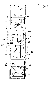
Fig. 1 schematically shows a longitudinal cross-section of a
wellbore machining device;
Fig. 2 schematically shows a cross-section of the machining
device seen along a line II-11 and
CA 02746468 2011-06-10
WO 2010/066276
PCT/EP2008/010596
- 7 -
Fig. 3 schematically shows a longitudinal cross-section of an
embodiment of the wellbore machining device providing for an internal flow
of fluid and
Figures 1 and 2 schematically show a machining device for
machining a tubular component, here a casing 1 down-hole of a wellbore.
The machining device comprises a control unit 3 at a surface level of the
bore hole and a down-hole tool unit 5 connected to the control unit 3 via a
wire line 7. The control unit 3 is in the form of a computer numerical control
device (CNC device) and is adapted to control an actual position of a tool
member 9 of the tool unit 5 and the actual position a plurality of machining
tools along at least three axes of motion with respect to a path and/or a
sequence of desired positions defined by data and a program stored in the
down-hole tool unit 5 or in the surface control unit 3. The tool member 9
comprises actuators in the form of electric servo motors schematically
indicated at 11, but not shown in detail, each of which comprises a position
detector or the like sensing the actual position of the tool member. The
position detector can sense the actual position, for example, with respect to
a scale 15 at the path of a longitudinal movement of the tool member 9 or to
a rotary encoder sensing the position of the electric motor or of a component
driven by the motor or the like to provide for a closed-loop position control
with respect of each of the axes of motion. Closed-loop position control is
common in the art of CNC devices.
The tool unit 5 comprises a longitudinal cylindrical guide member
17 which guides the tool member 9 movably along a first axis of motion 19
co-axially with the axis of the casing 1. On both ends of the guide member
17 anchor members 21 are mounted each having a plurality of radially
movable jacks 23 clamping the anchor member 21 towards the inner surface
of the casing 1. The jacks 23 are driven by electric motors and release the
anchor member in a radially retracted position thereof. The anchor members
21 support the tool unit 5 fixedly on the casing 1 to thus avoid vibrations
CA 02746468 2011-06-10
WO 2010/066276
PCT/EP2008/010596
- 8 -
during the machining operation. This enables the machining device to take
advantage from the precision of the CNC control and provides for precise,
smooth and efficient machining results.
As indicated at 36, a tool changing mechanism supporting a
plurality of machining tools 27" alternatively to or additionally to the
machining tools shown at 27, 27' or 27" can be provided on at least one of
the anchor members 21. The tool changing mechanism is capable of storing
a machining tool at a tool store and transferring individual tools between the
tool store and the tool member 9, for example by means of a transfer belt
(not shown). Of course, the tool changing mechanism can be provided on
the tool member 9 itself to change tools at the individual machining devices
thereof.
The tool member 9 comprises a carriage 25 carrying a plurality of
machining tools, for example a milling device 27 having a milling tool
rotating
around an axis 29 radially to an axis 31 of the cylindrical guide member 17.
The milling device 27 is movable along the axis 29 which thus forms a
second axis of motion of the tool member 9. Further, the carriage 25 is
rotatably supported on the guide member 17 with respect to the axis 31 to
provide for a third axis of motion as indicated at 33 in Fig. 2. By
controlling
the actuators 11 of the tool member 9 along the three axes of motion 19, 29
and 33, for example a window opening 35 can be milled into the casing 1.
it is a benefit of CNC controlling the tool member 9 that the
carriage 25 can support a plurality of machining tools or tool devices at
different positions so that the control unit 3 can change the tool during the
machining operation because differences in the position of the tools are
stored in the memory of the control unit 3. As indicated at 27', not only tool
devices of the same type can be provided on the carriage 25 for different
formation and/or contingency purposes, but also tool devices for different
machining purposes. For example, the tool unit 5 can comprise a welding
device with at least one welding electrode 27" which is supported on the
CA 02746468 2011-06-10
WO 2010/066276
PCT/EP2008/010596
- 9 -
carriage 25 and is movable along at least three axes of motion. The tool
member 9 can comprise at least one lathe tool to shorten the casing 1 while
rotating the carriage 25 around the axis 31. Further, the tool devices can
comprise logging devices (not shown) to measure the result of the machining
operation or can comprise heating or cooling devices (not shown), for
example, to harden or soften chemical substances used for sealing or
cladding of the casing 1. The tool devices may also comprise a cleaning or
polishing device (not shown) to clean or smoothen surfaces before or after
the machining operation.
The tool devices can, of course, be supported on the carriage 25
movable along further axes of motion as indicated at 37 in the example of a
tool device 39 pivotably supported on the carriage 25 at 41. For example a
fourth axis and a fifth axis can be provided by tilting the tool in two
perpendicular planes.
The casing 1 is a constituent part of a drilling fluid delivery
system further explained also in conjunction with Fig. 3. The drilling fluid
is
pumped down-hole and flows through the tool unit 5 along openings 43 of
the anchor member 21 and along an annulus 44 radially between the guide
member 17 and the casing 1 (arrows 45). The drilling fluid is used to
lubricate and to cool the machining action of the tool member 9. To prevent
debris from the machining operation and, in particular, cuttings from the
milling action from contaminating the wellbore as well as the cutting action
itself, at least the anchor member 21 remote from the wire line 7 but
preferably both anchor members 21 are sealed, for example, by means of an
0-ring 46 or an expandable sealing ring against the casing 1 so that the total
flow of drilling fluid must pass through the opening 43. The opening 43 of the
anchor member 21 remote from the wire line, e.g. the "bottom" anchor
member is covered by a particle collector preventing particles from exiting
the tool unit 5. The particle collector comprises a basket-like filter 47 and
at
least one, here a plurality of, magnets 49 to better collect steel cuttings
cut
from the casing 1. The debris is brought to the surface together with the tool
CA 02746468 2011-06-10
WO 2010/066276
PCT/EP2008/010596
- 10 -
unit 5 after having finished the machining operation without contaminating
the wellbore.
The tool member 9 is capable of being quickly and precisely
relocated to an original position which the tool unit 5 left after a first
machining step. The tool member 9 comprises a marking tool 51, for
example, a small drilling tool or milling tool for producing a reference mark
53 in the form of a small pit or groove in the inner surface of the casing 1
at a
position which is preferably defined by the control unit 3. For relocation of
the
tool unit 5 at the position defined by the reference mark 53, the tool member
9 is provided with a sensor device 55 adapted to detect the reference mark
53. The sensor device 55 may be an optical sensor or a non-contact sensor
or, as it is shown in Figure 1, a probe having a stylus for detecting the pit
or
groove of the reference mark 53. Of course, instead of a machined reference
mark, other kinds of sensable reference marks may be used, for example, a
painted spot or the like which is optically detected by an appropriate sensor
as explained above. Of course, reference marks may also be provided on
tube portions of the casing 1 before installing them in the well bore.
Figure 3 shows details of the drilling fluid delivery system. The
drilling fluid flows through the casing 1 down-hole and through the tool unit
5
including the anchor members 21 as explained in conjunction with Figure 1.
The down-hole flow of the drilling fluid is schematically shown by a dash-
point line 57 and is guided through the anchor members 21 and the annulus
44. The down-hole flow exits the tool unit 5 through the particle collector 47
into the free well. To preserve the fluid volume in the well, a return flow of
the
drilling fluid is directed through a conduit 59 extending along and through
the
guide member 17 and the anchor member 21 (see also Fig. 2). The conduit
59 extends through the total length of the tool unit and comprises extension
tubes 60 projecting outwardly from the tool unit 5. The extension tubes 60
open into the well and assure that a sufficient portion of the fluid exiting
the
lower anchor member 21 through the basket-like filter 47 or the upper
anchor member 21 through the conduit 59 are not directly recycled or short-
CA 02746468 2011-06-10
WO 2010/066276
PCT/EP2008/010596
- 11 -
circuited in the vicinity of the anchor members 21. The extension tubes 60
provide for better heat dissipation of the fluid.
Of course, the extension tubes 60 may be omitted.
Since the return flow is not directed through a tubing to the
surface level of the well, tripping of the tool unit 5 is very easy and not
time-
consuming. As may be easily understood, the conduit 59 may also be part of
a fluid return system leading to the surface level of the well as indicated at
61 in Fig. 3. Preferably, the tubing is in the form of a "coiled tubing"
extending between the tool unit 5 and the surface level of the well. But in
principle, it is enough to control flow through tool unit 5 in both
directions,
and leave the drilling fluid live its own life outside tool unit 5. The return
flow
is schematically shown with a dashed line 63.
The down-hole flow of drilling fluid enters the annulus 44 through
a filter 65 associated with the anchor member 21 adjacent the wire line 7,
e.g. the "upper" anchor member. A pump 67 forces the drill fluid through the
tool unit 5. In the embodiment of Fig. 3, the pump 67 is also associated with
the upper anchor member 21, but may also be associated with the lower
anchor member 21. The cleaned drilling fluid flowing down-hole the annulus
44 flushes and cools the machining tool 27 and washes debris and cuts into
the basket-like particle collector 47.