Note: Descriptions are shown in the official language in which they were submitted.
CA 02746524 2011-06-09
WO 2010/115850 PCT/EP2010/054448
1
Apparatus, Method and Computer Program for Upmixing a Downmix Audio Signal
using a Phase Value Smoothing
Technical Field
Embodiments according to the invention are related to an apparatus, a method,
and a
computer program for upmixing a downmix audio signal.
Some embodiments according to the invention are related to an adaptive phase
parameter
smoothing for parametric multi-channel audio coding.
Background of the Invention
In the following, the context of the invention will be described. Recent
development in the
area of parametric audio coding delivers techniques for jointly coding a multi-
channel
audio (e.g. 5.1) signal into one (or more) downmix channels plus a side
information
stream. These techniques are known as Binaural Cue Coding, Parametric Stereo,
and
MPEG Surround etc.
A number of publications describe the so-called "Binaural Cue Coding"
parametric multi-
channel coding approach, see for example references [1][2][3][4][5].
"Parametric Stereo" is a related technique for the parametric coding of a two-
channel
stereo signal based on a transmitted mono signal plus parameter side
information, see, for
example, references [6][7].
"MPEG Surround" is an ISO standard for parametric multi-channel coding, see,
for
example, reference [8].
The above-mentioned techniques are based on transmitting the relevant
perceptual cues for
a human's spatial hearing in a compact form to the receiver together with the
associated
mono or stereo downmix-signal. Typical cues can be inter-channel level
differences (ILD),
inter-channel correlation or coherence (ICC), as well as inter-channel time
differences
(ITD), inter-channel phase differences (IPD), and overall phase differences
(OPD).
These parameters are, in some cases, transmitted in a frequency and time
resolution
adapted to the human's auditory resolution.
CA 02746524 2011-06-09
WO 2010/115850 PCT/EP2010/054448
2
For the transmission, the parameters are typically quantized (or, in some
cases, even have
to be quantized), where often (especially for low-bit rate scenarios) a rather
coarse
quantization is used.
The update interval in time is determined by the encoder, depending on the
signal
characteristics. This means that, not for every sample of the downmix-signal,
parameters
are transmitted. In other words, in some cases a transmission rate (or
transmission
frequency, or update rate) of parameters describing the above-mentioned cues
may be
smaller than a transmission rate (or transmission frequency, or update rate)
of audio
samples (or groups of audio samples).
Instead of transmitting both inter-channel phase differences (IPDs) and
overall phase
differences (OPDs), it is also possible to only transmit inter-channel phase
differences
(IPDs) and estimate the overall phase differences (OPDs) in the decoder.
Since the decoder may, in some cases, have to apply the parameters
continuously over time
in a gapless manner, e.g. to each sample (or audio sample), intermediate
parameters may
need to be derived at decoder side, typically by interpolation between past
and current
parameter sets.
Some conventional interpolation approaches, however, result in poor audio
quality.
In the following, a generic binaural cue coding scheme will be described,
taking reference
to Fig. 7. Fig. 7 shows a block schematic diagram of a binaural cue coding
transmission
system 800, which comprises a binaural cue coding encoder 810 and a binaural
cue coding
decoder 820. The binaural cue coding encoder 810 may, for example, receive a
plurality of
audio signals 812a, 812b, and 812c. Further, the binaural cue coding encoder
810 is
configured to downmix the audio input signals 812a-812c using a downmixer 814
to obtain
a downmix signal 816, which may, for example, be a sum signal, and which may
be
designated with "AS" or "X". Further, the binaural cue coding encoder 810 is
configured
to analyze the audio input signals 812a-812c using an analyzer 818 to obtain
the side
information signal 819 ("SI"). The sum signal 816 and the side infoimation
signal 819 are
transmitted from the binaural cue coding encoder 810 to the binaural cue
coding decoder
820. The binaural cue coding decoder 820 may be configured to synthesize a
multi-channel
audio output signal comprising, for example, audio channels yl, y2,
, yN on the basis of
the sum signal 816 and inter-channel cues 824. For this purpose, the binaural
cue coding
CA 02746524 2011-06-09
WO 2010/115850 PCT/EP2010/054448
3
decoder 820 may comprise a binaural cue coding synthesizer 822, which receives
the sum
signal 816 and the inter-channel cues 824, and provides the audio signals yl,
y2,..., yN.
The binaural cue coding decoder 820 further comprises a side information
processor 826,
which is configured to receive the side information 819 and, optionally, a
user input 827.
The side information processor 826 is configured to provide the inter-channel
cues 824 on
the basis of the side information 819 and the optional user input 827.
To summarize, the audio input signals are analyzed and downmixed. The sum
signal plus
the side information is transmitted to the decoder. The inter-channel cues are
generated
from the side information and local user input. The binaural cue coding
synthesis generates
the multi-channel audio output signal.
For details, reference is made to the articles "Binaural Cue Coding Part H:
Schemes and
applications," by C. Faller and F. Baumgarte (published in: IEEE Transactions
on Speech
and Audio Processing, vol. 11, no. 6, Nov. 2003).
However, it has been found that many conventional binaural cue coding decoders
provide
multi-channel output audio signals with degraded quality if the side
information is
quantized coarsely or with insufficient resolution.
In view of this problem, there is a need for an improved concept of upmixing a
downmix
audio signal into an upmixed audio signal, which reduces a degradation of the
hearing
impression if the side information describing a phase relationship between
different
channels of the upmix signal is quantized with comparatively low resolution.
Summary of the Invention
An embodiment according to the invention creates an apparatus for upmixing a
downmix
audio signal describing one or more downmix audio channels into an upmixed
audio signal
describing a plurality of upmixed audio channels. The apparatus comprises an
upmixer
configured to apply temporally variable upmix parameters to upmix the downmix
signal in
order to obtain the upmixed audio signal. The temporally variable upmix
parameters
comprise temporally variable smoothened phase values. The apparatus further
comprises a
parameter determinator, which parameter determinator is configured to obtain
one or more
temporally smoothened upmix parameters to be used by the upmixer on the basis
of a
quantized upmix parameter input information. The parameter determinator is
configured to
combine a scaled version of a previous smoothened phase value with a scaled
version of an
CA 02746524 2011-06-09
WO 2010/115850 PCT/EP2010/054448
4
input phase information using a phase change limitation algorithm, to
determine a current
smoothened phase value on the basis of the previous smoothened phase value and
the input
phase infoiniation.
This embodiment according to the invention is based on the finding that
audible artifacts in
the upmix signals can be reduced or even avoided by combining a scaled version
of a
previous smoothened phase value with a scaled version of an input phase
information
using a phase change limitation algorithm, because the consideration of the
previous
smoothened phase value in combination with a phase change limitation algorithm
allows to
keep discontinuities of the smoothened phase values reasonably small. A
reduction of
discontinuities between subsequent smoothened phase values (for example, the
previous
smoothened phase value and the current smoothened phase value), in turn, helps
to avoid
(or keep sufficiently small) audible frequency variation at a transition
between portions of
an audio signal to which the subsequent phase values (e.g. the previous
smoothened phase
value and the current smoothened phase value) are applied.
To summarize the above, the invention creates a general concept of adaptive
phase
processing for parametric multi-channel audio coding. Embodiments according to
the
invention supersede other techniques by reducing artifacts in the output
signal caused by
coarse quantization or rapid changes of phase parameters.
In a preferred embodiment, the parameter determinator is configured to combine
the scaled
version of the previous smoothened phase value with the scaled version of the
input phase
information, such that the current smoothened phase value is in a smaller
angle region out
of a first angle region and a second angle region, wherein the first angle
region extends, in
a mathematically positive direction, from a first start direction defined by
the previous
smoothened phase value to a first end direction defined by the phase input
information, and
wherein the second angle region extends, in the mathematically positive
direction, from a
second start direction defined by the input phase information to a second end
direction
defined by the previous smoothened phase value. Accordingly, in some
embodiments of
the invention, a phase variation, which is introduced by a recursive (infinite
impulse
response type) smoothening of phase values, is kept as small as possible.
Accordingly,
audible artifacts are kept as small as possible. For example, the apparatus
may be
configured to ensure that the current smoothened phase value is located within
a smaller
angle range out of two angle ranges, wherein a first of the two angle ranges
covers more
than 180 and wherein a second of the angle ranges covers the less than 180 ,
and wherein
the two angle ranges together cover 360 . Accordingly, it is ensured by the
phase change
limitation algorithm that the phase difference between the previous smoothened
phase
CA 02746524 2011-06-09
WO 2010/115850 PCT/EP2010/054448
value and the current smoothened phase value is smaller than 1800 and,
preferably, even
smaller than 90 . This helps to keep audible artifacts as small as possible.
In a preferred embodiment, the parameter determinator is configured to select
a
5 combination rule out of a plurality of different combination rules in
dependence on a
difference between the phase input information and the previous smoothened
phase value,
and to determine the current smoothened phase value using the selected
combination rule.
Accordingly, it can be achieved that an appropriate combination rule is
chosen, which
ensures that the phase change between the previous smoothened phase value and
the
current smoothened phase value is below a predetermined threshold or, more
generally,
sufficiently small or as small as possible. Accordingly, the inventive
apparatus outperforms
comparable apparatus, which have a fixed combination rule.
In a preferred embodiment, the parameter determinator is configured to select
a basic
combination rule if a difference between the phase input information and the
previous
smoothened phase value is in a range between -7r and + it, and to select one
or more
different phase adaptation combination rules otherwise. The basic combination
rule defines
a linear combination without a constant summand of the scaled version of the
phase input
information and the scaled version of the previous smoothened phase value. The
one or
more phase adaptation combination rules define a linear combination, taking
into account a
constant phase adaptation summand, of the scaled version of the input phase
information
and the scaled version of the previous smoothened phase value. Accordingly, an
advantageous and easy-to-implement linear combination of the previous
smoothened phase
value and the input phase information can be performed, wherein an additional
summand
can be selectively applied if the difference between the previous smoothened
phase value
and the input phase information takes a comparatively large value (greater
than it or
smaller than - 7r). Accordingly, the problematic cases in which there is a
large difference
between the previous smoothened phase value and the input phase information
can be
handled with specifically adapted phase adaptation combination rules, which
allows
keeping the phase changes between subsequent smoothened phase values
sufficiently
small.
In a preferred embodiment, the parameter determinator comprises a smoothing
controller,
wherein the smoothing controller is configured to selectively disable a phase
value
smoothing functionality if a difference between the smoothened phase quantity
and the
corresponding input phase quantity is larger than a predetermined threshold
value.
Accordingly, the phase value smoothing functionality can be disabled if there
is a large
change in the input phase information. Typically, very large changes of the
input phase
CA 02746524 2011-06-09
WO 2010/115850 PCT/EP2010/054448
6
infoimation indicate that it is, indeed, desired to perform a non-smoothened
phase change,
because comparatively large changes of the input phase information
(significantly larger
than a quantization step) are often related to specific sound events within an
audio signal.
Thus, a smoothing of the phase values, which improves the auditory impression
in most
cases, would be detrimental in this specific case. Accordingly, the auditory
impression can
even be improved by selectively disabling the phase value smoothing
functionality.
In a preferred embodiment, the smoothing controller is configured to evaluate,
as the
smoothened phase quantity, a difference between two smoothened phase values
and to
evaluate, as the corresponding input phase quantity, a difference between two
input phase
values corresponding to the two smoothened phase values. It has been found
that in some
cases, a difference between phase values, which are associated with different
(upmixed)
channels of a multi-channel audio signal, is a particularly meaningful
quantity to decide
whether the phase value smoothing functionality should be enabled or disabled.
In a preferred embodiment, the upmixer is configured to apply, for a given
time portion,
different temporally smoothened phase rotations, which are defined by
different
smoothened phase values, to obtain signals of the upmixed audio channels
having an inter-
channel phase difference if a smoothing function (or a phase value smoothing
functionality) is enabled, and to apply temporally non-smoothened phase
rotations, which
are defined by different non-smoothened phase values, to obtain signals of
different of the
upmixed audio channels having an inter-channel phase difference if the
smoothing
function (or the phase value smoothing functionality) is disabled. In this
case, the
parameter determinator comprises a smoothing controller, which smoothing
controller is
configured to selectively enable or disable the phase value smoothing
functionality if a
difference between the smoothened phase values applied to obtain the signals
of the
different upmixed audio channels differs from a non-smoothened inter-channel
phase
difference value, which is received by the upmixer or derived from a received
information
by the upmixer, by more than a predetermined threshold value. It has been
found that a
selective deactivation of the phase value smoothing functionality is
particularly useful in
terms of improving the hearing impression if an inter-channel phase difference
value is
evaluated as the criterion for activating and deactivating the phase value
smoothing
functionality.
In a preferred embodiment, the parameter determinator is configured to adjust
the filter
time constant for detetmining a sequence of the smoothened phase values in
dependence
on a current difference between a smoothened phase value and a corresponding
input phase
value. By adjusting the filter time constant, it can achieved that a
sufficiently small settling
CA 02746524 2011-06-09
WO 2010/115850 PCT/EP2010/054448
7
time is obtained for very large changes of the input phase value, while
keeping the
smoothing characteristics sufficiently good for lower and medium changes of
the input
phase value. This functionality brings along particular advantages, because a
comparatively small (or, at most, medium-sized) change of the input phase
value is often
caused by a quantization granularity. In other words, a stepwise change of the
input phase
value, which is caused by a quantization granularity, may result in an
efficient operation of
the smoothing. In such a case, the smoothing functionality may be particularly
advantageous, wherein a comparatively long filter time constant brings good
results. In
contrast, a very large change of the input phase value, which is significantly
larger than a
quantization step, typically corresponds to a desired large change of the
phase value. In this
case, a comparatively short filter time constant brings along good results.
Accordingly, by
adjusting the filter time constant in dependence on a current difference
between a
smoothened phase value and a corresponding input phase value, it can be
reached that,
intentional large changes of the input phase value result in fast changes of
the smoothened
phase values, while comparatively small changes of the input phase value,
which take the
size of a quantization step, result in a comparatively slow and smoothed
transition of the
smoothened phase value. Accordingly, a good hearing impression is reached both
for
intentional, large changes of the desired phase value and for small changes of
the desired
phase value (which, nevertheless, may cause a change of the input phase value
by one
quantization step).
In a preferred embodiment, the parameter determinator is configured to adjust
a filter time
constant for determining a sequence of smoothened phase values in dependence
on
differences between a smoothened inter-channel phase difference, which is
defined by a
difference between two smoothened phase values associated with different
channels of the
upmixed audio signal, and a non-smoothened inter-channel phase difference,
which is
defined by a non-smoothened inter-channel phase difference information. It has
been found
that the concept of selectively adjusting the filter time constant can be used
with advantage
in combination with a processing of the inter-channel phase differences.
In a preferred embodiment, the apparatus for upmixing is configured to
selectively enable
or disable a phase value smoothing functionality in dependence on an
information
extracted from an audio bit stream. It has been found that an improvement of
the hearing
impression may be obtained by providing the possibility to selectively enable
or disable,
under the control of an audio encoder, a phase value smoothing functionality
in an audio
decoder.
CA 02746524 2011-06-09
WO 2010/115850 PCT/EP2010/054448
8
An embodiment according to the invention creates a method implementing the
functionality of the above-discussed apparatus for upmixing a downmix audio
signal into
an upmixed audio signal. Said method is based on the same ideas as the above-
discussed
apparatus.
In addition, embodiments according to the invention create a computer program
for
performing said method.
Brief Description of the Figs.
Embodiments according to the invention will subsequently be described taking
reference to
the accompanying Figs., in which:
Fig. 1 shows a block schematic diagram of an apparatus for
upmixing a
downmix audio signal, according to an embodiment of the invention;
Figs. 2a and 2b show a block schematic diagram of an apparatus for
upmixing a
downmix audio signal, according to another embodiment of the
invention;
Fig. 3 shows a schematic representation of overall phase
differences OPD1,
OPD2 and an inter-channel phase difference IPD;
Figs. 4a and 4b show graphical representations of phase relationships
for a first case
of the phase change limitation algorithm;
Figs. 5a and 5b show graphical representations of phase relationships
for a second
case of the phase change limitation algorithm;
Fig. 6 shows a flow chart of a method for upmixing a downmix audio
signal into an upmixed audio signal, according to an embodiment of
the invention; and
Fig. 7 shows a block schematic diagram representing a generic
binaural cue
coding scheme.
CA 02746524 2014-02-28
9
Detailed Description of the Embodiments
1. Embodiment according to Fig. 1
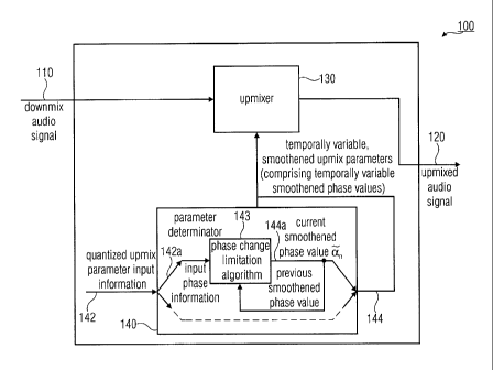
Fig. 1 shows a block schematic diagram of an apparatus 100 for upmixing a
downmix audio signal,
according to an embodiment of the invention. The apparatus 100 is configured
to receive a downmix
audio signal 110 describing one or more downmix audio channels and to provide
an upmixed audio
signal 120 describing a plurality of upmixed audio channels. The apparatus 100
comprises an upmixer
130 configured to apply temporally variable upmix parameters to upmix the
downmix audio signal 110
in order to obtain the upmixed audio signal 120. The apparatus 100 also
comprises a parameter
determinator 140 configured to receive quantized upmix parameter input
information 142. The
parameter determinator 140 is configured to obtain one or more temporally
smoothened upmix
parameters 144 for usage by the upmixer 130 on the basis of the quantized
upmix parameter input
information 142.
The parameter determinator 140 is configured to combine a scaled version of a
previous smoothened
phase value with a scaled version of an input phase information 142a, which is
included in the quantized
upmix parameter input information 142, using a phase change limitation
algorithm 143, to determine a
current smoothened phase value 144a on the basis of the previous smoothened
phase value and the input
phase information. The current smoothened phase value 144a is included in the
temporally variable,
smoothened upmix parameters 144.
In the following, some details regarding the functionality of the apparatus
100 will be described. The
downmix audio signal 110 is input into the upmixer 130, for example, in the
form of a sequence of sets
of complex values representing the dowmix audio signal in the time-frequency
domain (describing
overlapping or non-overlapping frequency bands or frequency subbands at an
update rate determined by
the encoder not shown here). The upmixer 130 is configured to linearly combine
multiple channels of
the downmix audio signal 110 in dependence on the temporally variable,
smoothened upmix parameters
and/or to linearly combine a channel of the downmix audio signal 110 with an
auxiliary signal (e.g. de-
correlated signal) (wherein the auxiliary signal may be derived from the same
audio channel of the
downmix audio signal 110, from one or more other audio channels of the downmix
audio signal 110, or
from a combination of audio channels of the dowmix audio signal 110). Thus,
the temporally variable,
smoothened upmix parameters 144 may be used by the upmixer 130 to decide upon
the amplitude
scaling and/or a phase rotation
CA 02746524 2011-06-09
WO 2010/115850 PCT/EP2010/054448
(or time delay) used in a generation of the upmixed audio signal 120 (or a
channel thereof)
on the basis of the downmix audio signal 110.
The parameter determinator 140 is typically configured to provide temporally
variable,
5 smoothened upmix parameters 144 at an update rate, which is equal to (or,
in some cases,
higher than) the update rate of the side information described by the
quantized upmix
parameter input infounation 142. The parameter deteuninator 140 may be
configured to
avoid (or, at least, reduce) artifacts arising from a coarse (bit rate saving)
quantization of
the quantized upmix parameter input information 142. For this purpose, the
parameter
10 determinator 140 may apply a smoothening of the phase information
describing, for
example, inter-channel phase differences. This smoothening of the input phase
information
142a, which is included in the quantized upmix parameter input information
142, is
performed using a phase change limitation algorithm 143, such that large and
abrupt
changes of the phase, which would result in audible artifacts, are avoided
(or, at least,
limited to a tolerable degree).
The smoothening is preferably performed by combining a previous smoothened
phase
value with a value of the input phase information 142a, such that a current
smoothened
phase value is dependent both on the previous smoothened phase value and the
current
value of the input phase information 142a. By doing so, a particularly smooth
transition
can be obtained using a simple structure of the smoothing algorithm. In other
words,
disadvantages of a finite-impulse-response smoothing can be avoided by
providing an
infinite-impulse-response type smoothening in which the previous smoothened
phase value
is considered.
Optionally, the parameter determinator 140 may comprise an additional
interpolation
functionality, which is advantageous if the quantized upmix parameter input
information
142 is transmitted at comparatively long temporal intervals (for example, less
than once
per set of spectral values of the downmix audio signal 110).
To summarize, the apparatus 100 allows for the provision of temporally
variable
smoothened phase values 144a on the basis of the quantized upmix parameter
input
information 142, such that the temporally variable smoothened phase values
144a are well-
suited for the derivation of the upmixed audio signal 120 from the downmix
audio signal
110 using the upmixer 130.
Audible artifacts are reduced (or even eliminated) by providing the smoothened
phase
value 144a using the above-discussed concept, wherein a consideration of a
previous
CA 02746524 2011-06-09
WO 2010/115850 PCT/EP2010/054448
11
smoothened phase value is combined with a phase change limitation.
Accordingly, a good
hearing impression of the upmixed audio signal 120 is achieved.
2. Embodiment according to Fig. 2
2.1. Overview over the Embodiment of Fig. 2
Further details regarding the structure and operation of an apparatus for
upmixing an audio
signal will be described taking reference to Figs. 2a and 2b. Figs. 2a and 2b
show a
detailed block schematic diagram of an apparatus 200 for mixing a downmix
audio signal,
according to another embodiment of the invention.
The apparatus 200 can be considered as a decoder for generating a multi-
channel (e.g. 5.1)
audio signal on the basis of a downmix audio signal 210 and a side information
SI. The
apparatus 200 implements the functionalities, which have been described with
respect to
the apparatus 100.
The apparatus 200 may, for example, serve to decode a multi-channel audio
signal encoded
according to a so-called "Binaural Cue Coding", a so-called "Parametric
Stereo" or a so-
called "MPEG Surround". Naturally, the apparatus 200 may similarly be used to
upmix
multi-channel audio signals encoded according to other systems using spatial
cues.
For simplicity, the apparatus 200 is described, which performs an upmix of a
single
channel downmix audio signal into a two-channel signal. However, the concept
described
here can easily be extended to cases in which the downmix audio signal
comprises more
than one channel, and also to cases in which the upmixed audio signal
comprises more than
two channels.
2.2. Input Signals and Input Timing of the Embodiment of Fig. 2
The apparatus 200 is configured to receive the downmix audio signal 210 and
the side
information 212. Further, the apparatus 200 is configured to provide an
upmixed audio
signal 214 comprising, for example, multiple channels.
The downmix audio signal 210 may, for example, be a sum signal generated by an
encoder
(e.g. by the BCC encoder 810 shown in Fig. 7). The dowmix audio signal 210
may, for
instance, be represented in a time-frequency domain, for example, in the form
of a
complex-valued frequency decomposition. For instance, audio contents of a
plurality of
CA 02746524 2011-06-09
WO 2010/115850 PCT/EP2010/054448
12
frequency subbands (which may be overlapping or non-overlapping) of the audio
signal
may be represented by corresponding complex values. For a given frequency
band, the
dowmix audio signal may be represented by a sequence of complex values
describing the
audio content in the frequency subband under consideration for subsequent
(overlapping or
non-overlapping) time intervals. The subsequent complex values for subsequent
time
intervals may be obtained, for example, using a filterbarik (e.g. QMF
filterbank), a Fast
Fourier Transform, or the like, in the apparatus 100 (which may be part of a
multi-channel
audio signal decoder), or in an additional device coupled to the apparatus
100. However,
the representation of the downmix audio signal 210 described here is typically
not identical
to the representation of the downmix signal used for a transmission of the
dowmix audio
signal from a multi-channel audio signal encoder to a multi-channel audio
signal decoder
or to the apparatus 100. Accordingly, the downmix audio signal 210 may be
represented by
a stream of sets or vectors of complex values.
In the following, it will be assumed that subsequent time intervals of the
downmix audio
signal 210 are designated with an integer-valued index k. It will also be
assumed that the
apparatus 200 receives one set or vector of complex values per interval k and
per channel
of the downmix audio signal 210. Thus, one sample (set or vector of complex
values) is
received for every audio sample update interval described by time index k.
In other words, audio samples ("AS") of the downmix audio signal 210 are
received by the
apparatus 210, such that a single audio sample AS is associated with each
audio sample
update interval k.
The apparatus 200 further receives a side information 212 describing the upmix
parameters. For instance, the side information 212 may describe one or more of
the
following upmix parameters: Inter-channel level difference (ILD), inter-
channel
correlation (or coherence) (ICC), inter-channel time difference (ITD), inter-
channel phase
difference (IPD) or overall-phase difference (OPD). Typically, the side
information 212
comprises the ILD parameters and at least one out of the parameters ICC, ITD,
IPD, OPD.
However, in order to save bandwidth, the side information 212 is, in some
embodiments,
only transmitted towards, or received by, the apparatus 200 once per multiple
of the audio
sample update intervals k of the downmix audio signal 210 (or the transmission
of a single
set of side information may be temporally spread over a plurality of audio
sample update
intervals k). Thus, in some cases, there is only one set of side information
parameters for a
plurality of audio sample update intervals k. However, in other cases, there
may be one set
of side information parameters for each audio sample update interval k.
CA 02746524 2011-06-09
WO 2010/115850 PCT/EP2010/054448
13
Intervals at which the side infoimation is updated are designed with the index
n, wherein,
for the sake of simplicity only, it will be assumed in the following that the
subsequent time
intervals of the downmix audio signal 210, which are designated with the
integer-value
index k, are identical to the time intervals at which the side information SI
212 is updated,
such that the relationship k=n holds. However, if an update of the side
information SI 212
is performed only once per a plurality of subsequent time intervals k of the
downmix audio
signal 210, an interpolation may be performed, for example, between subsequent
input
phase information values an or subsequent smoothened phase values 6i n=
For example, side information may be transmitted to (or received by) the
apparatus 200 at
the audio sample update intervals k=4, k=8 and k=16. In contrast, no side
information 212
may be transmitted to (or received by) the apparatus between said audio sample
update
intervals. Thus, the update intervals of the side information 212 may vary
over time, as the
encoder may, for example, decide to provide a side information update only
when required
(e.g. when the decoder recognizes that the side infoilliation is changed by
more than a
predetermined value). For example, the side information received by the
apparatus 200 for
the audio sample update interval k=4 may be associated with the audio sample
update
intervals k=3, 4, 5. Similarly, the side information received by the apparatus
200 for the
audio sample update interval k=8 may be associated with the audio sample
update intervals
k=6, 7, 8, 9, 10, and so on. However, a different association is naturally
possible and the
update intervals for the side information may naturally also be larger or
smaller than
discussed.
2.3. Output Signals and Output Timing of the Embodiment of Fig. 2
However, the apparatus 200 serves to provide upmixed audio signals in a
complex-valued
frequency composition. For example, the apparatus 200 may be configured to
provide the
upmixed audio signals 214, such that the upmixed audio signals comprise the
same audio
sample update interval or audio signal update rate as the downmix audio signal
210. In
other words, for each sample (or audio sample update interval k) of the
downmix audio
signal 210, a sample of the upmixed audio signal 214 is generated in some
embodiments.
2.4. Upmix
In the following, it will be described in detail how an update of the upmix
parameters,
which are used for upmixing the downmix audio signal 210, can be obtained for
each audio
sample update interval k even though the decoder input side information 212
may be
updated, in some embodiments, only at larger update intervals. In the
following, the
CA 02746524 2011-06-09
WO 2010/115850 PCT/EP2010/054448
14
processing for a single subband will be described, but the concept can
naturally be
extended to multiple subbands.
The apparatus 200 comprises, as a key component, an upmixer 230, which is
configured to
operate as a complex-valued linear combiner. The upmixer 230 is configured to
receive a
sample x(t) or x(k) of the downmix audio signal 210 (e.g. representing a
certain frequency
band) associated with the audio sample update interval k. The signal x(t) or
x(k) is
sometimes also designated as "dry signal". In addition, the upmixer 230 is
configured to
receive samples q(t) or q(k) representing a de-correlated version of the
downmix audio
signal.
Further, the apparatus 200 comprises a de-correlator (e.g. a delayer or
reverberator) 240,
which is configured to receive samples x(k) of the downmix audio signal and to
provide,
on the basis thereof, samples q(k) of a de-correlated version of the downmix
audio signal
(represented by x(k)). The de-correlated version (samples q(k)) of the dowmix
audio signal
(samples x(k)) may be designated as "wet signal".
The upmixer 230 comprises, for example, a matrix-vector multiplier 232, which
is
configured to perform a real-valued (or, in some cases, complex-valued) linear
combination of the "dry signal" (represented by x(k)) and the "wet signal"
(represented by
q(k)) to obtain a first upmixed channel signal (represented by samples yi(k))
and a second
upmixed channel signal (represented by samples y2(k)). The matrix-vector
multiplier 232
may, for example, be configured to perform the following matrix-vector
multiplication to
obtain the samples yi(k) and y2(k) of the upmixed channel signals:
y1(k) x(k)1
=11(k)
_Y2 (k) _ q(k)]
The matrix-vector multiplier 232, or the complex-valued linear combiner 230,
may further
comprise a phase adjuster 233, which is configured to adjust phases of the
samples yi(k)
and y2(k) representing the upmixed channel signals. For example, the phase
adjustor 233
may be configured to obtain the phase-adjusted first upmixed channel signal,
which is
represented by samples )71(k) according to
(k)
1(k) =
CA 02746524 2011-06-09
WO 2010/115850 PCT/EP2010/054448
and to obtain the phase adjusted second upmixed channel signal, which is
represented by
samples ji 2(k), according to
k
'5)- 2(k) = eja2 y2 (k).
5
Accordingly, the upmixed audio signal 214, samples of which are designated
with 51 i(k)
and j; 2(k), is obtained on the basis of the dry signal and the wet signal, by
the complex-
valued linear combiner 230 using the temporally variable upmix parameters. The
temporally variable smoothened phase values n are used to determine the phases
(or
10 inter-channel phase differences) of the upmixed audio signals ji i(k)
and 512(k). For
example, the phase adjustor 232 may be configured to apply the temporally
variable
smoothened phase values. However, alternatively, the temporally variable
smoothened
phase values may already be used by the matrix vector multiplier 232 (or even
in the
generation of the entries of the matrix H). In this case, the phase adjuster
233 may be
15 omitted entirely.
2.5 Update Of The Upmix Parameters
As can be seen from the above equations, it is desirable to update the upmix
parameter
matrix H(k) and the upmix channel phase values ai(k), a2(k) for each audio
sample update
interval k. Updating the upmix parameter matrix for each audio sample update
interval k
brings the advantage that the upmix parameter matrix is always well-adapted to
the actual
acoustic environment. Updating the upmix parameter matrix for every audio
sample update
interval k also allows keeping step-wise changes of the upmix parameter matrix
H (or of
the entries thereof) between subsequent audio sample intervals k small, as
changes of the
upmix parameter matrix are distributed over multiple audio sample update
intervals, even
if the side information 212 is updated only once per multiple of the audio
sample update
intervals k. Also, it is desirable to smoothen any changes of the upmix
parameter matrix H
which would arise from a quantization of the side information SI, 212.
Similarly, it is
desirable to update the upmix channel phase values al(k) and a2(k)
sufficiently often, in
order to avoid, at least during a continuous audio signal, step-wise changes
of said upmix
channel phase values. Also, it is desirable to temporally smoothen the upmix
channel phase
values, in order to reduce or avoid artifacts that could be caused by a
quantization of the
side information SI, 212.
The apparatus 200 comprises a side information processing unit 250, which is
configured
to provide the temporally variable upmix parameters 262, for instance, the
entries Fl,i (k) of
CA 02746524 2011-06-09
WO 2010/115850 PCT/EP2010/054448
16
the matrix 11(k) and the upmix channel phase values ai(k), a2(k), on the basis
of the side
information 212. The side information processing unit 250 is, for example,
configured to
provide an updated set of upmix parameters for every audio sample update
interval k, even
if the side information 212 is updated only once per multiple audio sample
update intervals
k. However, in some embodiments the side information processing 250 may be
configured
to provide an updated set of temporally variable smoothing upmix parameter
less often, for
example only once per update of the side information SI, 212.
The side information processing unit 250 comprises an upmix parameter input
information
determinator 252, which is configured to receive the side information 212 and
to derive, on
the basis thereof, one or more upmix parameters (for example in the form of a
sequence
254 of magnitude values of upmix parameters and a sequence 256 of phase values
of
upmix parameters), which may be considered as a upmix parameter input
information
(comprising, for example, an input magnitude information 254 and an input
phase
information 256). For example, the upmix parameter input information
determinator 252
may combine a plurality of cues (e.g., ILD, ICC, ITD, IPD, OPD) to obtain the
upmix
parameter input information 254, 256, or may individually evaluate one or more
of the
cues. The upmix parameter input information determinator 252 is configured to
describe
the upmix parameters in the form of a sequence 254 of input magnitude values
(also
designated as input magnitude information) and a separate sequence 256 of
input phase
values (also designated as input phase information). The elements of the
sequence 256 of
input phase values may be considered as an input phase information an. The
input
magnitude values of the sequence 254 may, for example, represent an absolute
value of a
complex number, and the input phase values of the sequence 256 may, for
example,
represent an angle value (or phase value) of the complex number (measured, for
example,
with respect to a real-part-axis in a real-part-imaginary-part orthogonal
coordinate system).
Thus, the upmix parameter input information determinator 252 may provide the
sequence
254 of input magnitude values of upmix parameters and the sequence 256 of
input phase
values of upmix parameters. The upmix parameter input information determinator
252 may
be configured to derive from one set of side information a complete set of
upmix
parameters (for example, a complete set of matrix elements of the matrix H and
a complete
set of phase values al, a2). There may be an association between a set of side
information
212 and a set of input upmix parameters 254,256. Accordingly, the upmix
parameter input
information determinator 252 may be configured to update the input upmix
parameters of
the sequences 254, 256 once per upmix parameter update interval, i.e., once
per update of
the set of side information.
CA 02746524 2011-06-09
WO 2010/115850 PCT/EP2010/054448
17
The side information processing unit further comprises a parameter smoother
(sometimes
also designated briefly as "parameter deterrninator") 260, which will be
described in detail
in the following. The parameter smoother 260 is configured to receive the
sequence 254 of
the (real-valued) input magnitude values of upmix parameters (or matrix
elements) and the
sequence 256 of (real-valued) input phase values of upmix parameters (or
matrix
elements), which may be considered as an input phase information an. Further,
the
parameter smoother is configured to provide a sequence of temporally variable
smoothened upmix parameters 262 on the basis of a smoothing of the sequence
254 and
the sequence 256.
The parameter smoother 260 comprises a magnitude-value smoother 270 and a
phase value
smoother 272.
The magnitude-value smoother is configured to receive the sequence 254 and
provide, on
the basis thereof, a sequence 274 of smoothened magnitude values of upmix
parameters (or
of matrix elements of a matrix 14 n). The magnitude value smoother 270 may,
for example,
be configured to perform a magnitude value smoothing, which will be discussed
in detail
below.
Similarly, the phase value smoother 272 may be configured to receive the
sequence 256
and to provide, on the basis thereof, a sequence 276 of temporally variable
smoothened
phase values of upmix parameters (or of matrix values). The phase value
smoother 272
may, for example, be configured to perform a smoothing algorithm, which will
be
described in detail below.
In some embodiments, the magnitude value smoother 270 and the phase value
smoother
are configured to perform the magnitude value smoothing and the phase value
smoothing
separately or independently. Thus, the magnitude values of the sequence 254 do
not affect
the phase value smoothing, and the phase values of the sequence 256 do not
affect the
magnitude value smoothing. However, it is assumed that the magnitude value
smoother
270 and the phase value smoother 272 operate in a time-synchronized manner
such that the
sequences 274, 276 comprise corresponding pairs of smoothened magnitude values
and
smoothened phase values of upmix parameters.
Typically, the parameter smoother 260 acts separately on different upmix
parameters or
matrix elements. Thus, the parameter smoother 260 may receive one sequence 254
of
magnitude values for each upmix parameter (out of a plurality of upmix
parameters) or
matrix element of the matrix IL Similarly, the parameter smoother 260 may
receive one
CA 02746524 2011-06-09
WO 2010/115850 PCT/EP2010/054448
18
sequence 256 of input phase values ar, for phase adjustment of each upmixed
audio
channel.
2.6 Details Regarding The Parameter Smoothing
In the following, details regarding an embodiment of the present invention,
which reduces
phase processing artifacts caused by the quantization of IPDs/OPDs and/or the
estimation
of OPDs in a decoder, will be described. For simplicity, the following
description restricts
to an upmix from one to two channels only, without restricting the general
case of an
upmix from m to n channels, where the same techniques could be applied.
The decoder's upmix procedure from, for example, one to two channels is
carried out by a
matrix multiplication of a vector consisting of the downmix signal x (also
designated with
x(k)), called the dry signal, and a decorrelated version of the downmix signal
q (also
designated with q(k)), called the wet signal, with an upmix matrix H. The wet
signal q has
been generated by feeding the downmix signal x through a de-correlation filter
240. The
upmix signal y is a vector containing the first and second channel (e.g.,
yi(k) and y2(k)) of
the output. All signals x, q, y may be available in a complex-valued frequency
decomposition (e.g., time-frequency-domain representation).
This matrix operation is performed (for example, separately) for all subband
samples of
every frequency band (or at least for some subband samples of some frequency
bands). For
instance, the matrix operation may be performed in accordance with the
following
equation:
-
Y1
=--Hx
_Y2_ _q_ =
The coefficients of the upmix matrix H are derived from the spatial cues,
typically ILDs
and ICCs, resulting in real-valued matrix elements that basically perform a
mix of dry and
wet signals for each channel based on the ICCs, and adjust the output levels
of both output
channels as determined by the ILDs.
For the transmission of the spatial cues (e.g., ILD, ICC, ITD, IPD and/or OPD)
it is
desirable (or even necessary) to quantize some or all types of parameters in
the encoder.
Especially for low bit rate scenarios, it is often desirable (or even
necessary) to use a rather
coarse quantization to reduce the amount of transmitted data. However, for
certain types of
signals, a coarse quantization may result in audible artifacts. To reduce
these artifacts, a
CA 02746524 2011-06-09
WO 2010/115850 PCT/EP2010/054448
19
smoothing operation may be applied to the elements of the upmix matrix H to
smooth the
transition between adjacent quantizer steps, which is causing the artifacts.
The smoothing is performed, for example, by a simple low-pass filtering of the
matrix
elements:
H11 =-- 6 H11+(1- 6) ft n_i
This smoothing may, for example, be performed by the magnitude value smoother
270,
wherein the current input magnitude information Hn (e.g. provided by the upmix
parameter
input information determinator 252 and designated with 254) may be combined
with a
previous smoothened magnitude value (or magnitude matrix) ILI, in order to
obtain a
current smoothened magnitude value (or magnitude matrix) Hõ.
As smoothing may have a negative effect on signal portions, where the spatial
parameters
change rapidly, the smoothing may be controlled by additional side information
transmitted from the encoder.
In the following, the application and determination of the phase values will
be described in
more detail. If IPDs and/or OPDs are used, an additional phase shift may be
may be
applied to the output signals (for example, to the signals defined by the
samples yl (k) and
y2 (k)). The IPD describes the phase difference between the two channels (for
example, the
phase-adjusted first upmix channel signal defined by the samples y i (k) and
the phase-
adjusted second upmix channel signal defined by the samples Y 2 (k)) while on
OPD
describes a phase difference between one channel and the downmix.
In the following, the definition of the IPDs and the OPDs will be briefly
explained taking
reference to Fig. 3, which shows a schematic representation of phase
relationships between
the downmix signal and a plurality of channel signals. Taking reference now to
Fig. 3, a
phase of the downmix signal (or of a spectral coefficient x(k) thereof) is
represented by a
first pointer 310. A phase of a phase-adjusted first upmixed channel signal
(or of a spectral
coefficient y1 (k) thereof) is represented by a second pointer 320. A phase
difference
between the downmix signal (or a spectral value or coefficient thereof) and
the phase-
CA 02746524 2011-06-09
WO 2010/115850 PCT/EP2010/054448
adjusted first upmixed channel signal (or a spectral coefficient thereof) is
designated with
OPD1. A phase-adjusted second upmix channel signal (or a spectral coefficient
j-1 2 (k)
thereof) is represented by a third pointer 330. A phase difference between the
downmix
signal (or the spectral coefficient thereof) and the phase-adjusted second
upmixed channel
5 signal (or the spectral coefficient thereof) is designated with OPD2. A
phase difference
between the phase-adjusted first upmixed channel signal (or a spectral
coefficient thereof)
and the phase-adjusted second upmixed channel signal (or a spectral
coefficient thereof) is
designated with IPD.
To reconstruct the phase properties of the original signal (for example, to
provide the
phase-adjusted first upmixed channel signal and the phase-adjusted second
upmixed
channel signal with appropriate phases on the basis of the dry signal) the
OPDs for both
channels should be known. Often, the IPD is transmitted together with one OPD
(the
second OPD can then be calculated from these). To reduce the amount of
transmitted data,
it is also possible to only transmit IPDs and to estimate the OPDs in the
decoder, using the
phase infoimation contained in the downmix signal together with the
transmitted ILDs and
IPDs. This processing may, for example, be performed by the upmix parameter
input
information determinator 252.
The phase reconstruction in the decoder (for example, in the apparatus 200) is
performed
by a complex rotation of the output subband signals (for example of the
signals described
by the spectral coefficient yi (k), y2 (k)) in accordance with the following
equations:
jal
Y-1 = e Yi
ja 2
Y2 = e Y2 r
In the above equations, the angles al and a2 are equal to the OPDs for the two
channels (or,
for example, the smoothened OPDs).
As described above, coarse quantization of parameters (for example ILD
parameters and/or
ICC parameters) can result in audible artifacts, which is also true for
quantization of IPDs
and OPDs. As the above described smoothing operation is applied to the
elements of the
upmix matrix 1-1õ, it only reduces artifacts caused by quantization of ILDs
and ICCs, while
those caused by quantization of phase parameters are not affected.
CA 02746524 2011-06-09
WO 2010/115850 PCT/EP2010/054448
21
Furthermore, additional artifacts may be introduced by the above-described
time-variant
phase rotation, which is applied to each output channel. It has been found
that, if the phase
shift angles al and a2 fluctuate rapidly over time, the applied rotation angle
may cause a
short dropout or a change of the instantaneous signal frequency.
Both of these problems can be reduced significantly by applying a modified
version of the
above-described smoothing approach to the angles al and a2. As in this case,
the
smoothing filter is applied to angles, which wrap around every 27E, it is
preferable to
modify the smoothing filter by a so-called unwrapping. Accordingly, a
smoothened phase
value-c-i , is computed according to the following algorithm, which typically
provides for a
limitation of a phase change:
(g(an ¨2rc)+ (1¨ (5)Czn_, ) mod 27t- if (a,¨ a-n_1)> g
cin =(8(an+270+ (1¨ g)i n_i) mod 2rc if (an¨ oin_1) <¨rt-
I
8an+(1-8)a-n_1 else
In the following, the functionality of the above-described algorithm will be
briefly
discussed taking reference to Figs. 4a, 4b, 5a and 5b. Taking reference to the
above
equation or algorithm for the computation of the current smoothened phase
value Ei õ, it
can be seen that the current smoothened phase value 61 n is obtained by a
weighted linear
combination, without an additional summand, of the current input phase
information a,
and the previous smoothened phase value-d,-I, if a difference between the
values an and
-dn_I is smaller than or equal to it ("else" case of the above equation).
Assuming that 6 is a
parameter between zero and one (excluding zero and one), which determines (or
represents) a time constant of the smoothing process, the current smoothened
phase value
6%, will lie between the values of an and bi n_l. For example, if 6 = 0.5, the
value of Si õ is
the average (arithmetic mean) between an and'cin-1.
However, if the difference between a, and al n_l is larger than it, the first
case (line) of the
above equation is fulfilled. In this case, the current smoothened phase value
Et , is obtained
by a linear combination of a, and -6i n-1, taking into consideration a
constant phase
modification term -276. Accordingly, it is achieved that a difference between
andn and 6i n-1
is kept sufficiently small. An example of this situation is shown is Fig. 4a,
wherein the
phase Ei n_i is illustrated by a first pointer 410, the phase an is
illustrated by a second
pointer 412 and the phase Ein is illustrated by a third pointer 414.
CA 02746524 2011-06-09
WO 2010/115850 PCT/EP2010/054448
22
Fig. 4b illustrates the same situation for different values
and an. Again, the phase
values Ei an and än are illustrated by pointers 450, 452, 454.
Again, it is achieved that the angle difference between-de ri and bi n.1 is
kept sufficiently
small. In both cases, the direction defined by the phase value az is the
smaller one of two
angle regions, wherein the first of the two angle regions would be covered by
rotating the
pointer 410, 450 towards the pointer 412, 452 in a mathematically positive
(counter-
clockwise) direction, and wherein the second angle region would be covered by
rotating
the pointer 412, 452 towards the pointers 410, 450 in the mathematically
positive (counter-
clockwise) direction.
However, if it is found that the difference between the phase values an and
Ein-I is smaller
than -7C, the value of n is obtained using the second case (line) of the above
equation. The
phase value n is obtained by a linear combination of the phase values an and
Et n-I, with a
constant phase adaptation term 2n6. Examples of this case, in which a
-n
n_i is smaller
than -7E, are illustrated in Figs. 5a and 5b.
To summarize, the phase value smoother 272 may be configured to select
different phase
value calculation rules (which may be linear combination rules) in dependence
on the
difference between the values an and Ei
2.7 Optional Extensions of the Smoothening Concept
In the following, some optional extensions of the above-discussed phase value
smoothing
concept will be discussed. As for the other parameters (e.g., ILD, ICC, ITD)
there may be
signals, where a fast change of the rotation angles is necessary, for example,
if the IPD of
the original signal (for example a signal processed by an encoder) changes
rapidly. For
such signals, the smoothing, which is performed by the phase value smoother
272, would
(in some cases) have a negative effect on the output quality and should not be
applied in
such cases. To avoid a possible bit rate overhead required for controlling the
smoothing
from the encoder for every signal processing band, an adaptive smoothing
control (for
example, implemented using a smoothing controller) can be used in the decoder
(for
example in the apparatus 200): the resulting IPD (i.e., the difference between
the two
smoothed angles, for example between the angles al (k) and a2 (k)) is computed
and is
compared to the transmitted IPD (for example an inter-channel phase difference
described
by the input phase information an). If a difference is greater than a certain
threshold,
smoothing may be disabled and the unprocessed angles (for example the angles
an
described by the input phase information and provided by the upmix parameter
input
CA 02746524 2011-06-09
WO 2010/115850 PCT/EP2010/054448
23
information determinator) may be used (for example by the phase adjuster 233),
and
otherwise the low-pass filtered angle (e.g., the smoothened phase values Ei n
provided by
the phase value smoother 272) may be applied to the output signal (for example
by the
phase adjuster 233).
In an (optional) advanced version, the algorithm, which is applied by the
phase value
smoother 272, could be extended using a variable filter time constant, which
is modified
based on the current difference between processed and unprocessed IPDs. For
example, the
value of the parameter 6 (which determines the filter time constant) can be
adjusted in
dependence on a difference between the current smoothened phase value'n and
the
current input phase value an, or in dependence on a difference between the
previous
smoothened phase value Et n_i and the current input phase value an.
In some embodiments, additionally a single bit can (optionally) be transmitted
in the bit
stream (which represents the downmix audio signal 210 and the side information
212) to
completely enable or disable the smoothing from the encoder for all bands in
case of
certain critical signals, for which the adaptive smoothing control does not
give optimal
results.
3. Conclusion
To summarize the above, a general concept of adaptive phase processing for
parametric
multi-channel audio coding has been described. Embodiments according to the
current
invention supersede other techniques by reducing artifacts in the output
signal caused by
coarse quantization or rapid changes of phase parameters.
4. Method
An embodiment according to the invention comprises a method for upmixing a
downmix
audio signal describing one or more downmix audio channels into an upmixed
audio signal
describing a plurality of upmixed audio channels. Fig. 6 shows a flow chart of
such a
method, which is designated in its entirety with 700.
The method 700 comprises a step 710 of combining a scaled version of a
previous
smoothened phase value with a scaled version of a current phase input
information using a
phase change limitation algorithm, to determine a current smoothened phase
value on the
basis of the previous smoothened phase value and the input phase information.
CA 02746524 2011-06-09
WO 2010/115850 PCT/EP2010/054448
24
The method 700 also comprises a step 720 of applying temporally variable upmix
parameters to upmix a downmix audio signal in order to obtain an upmixed audio
signal,
wherein the temporally variable upmix parameter comprises temporally
smoothened phase
values.
Naturally, the method 700 can be supplemented by any of the features and
functionalities,
which are described herein with respect to the inventive apparatus.
5. Implementation Alternatives
Although some aspects have been described in the context of an apparatus, it
is clear that
these aspects also represent a description of the corresponding method, where
a block or
device corresponds to a method step or a feature of a method step.
Analogously, aspects
described in the context of a method step also represent a description of a
corresponding
block or item or feature of a corresponding apparatus. Some or all of the
method steps may
be executed by (or using) a hardware apparatus, like for example, a
microprocessor, a
programmable computer or an electronic circuit. In some embodiments, some one
or more
of the most important method steps may be executed by such an apparatus.
Depending on certain implementation requirements, embodiments of the invention
can be
implemented in hardware or in software. The implementation can be performed
using a
digital storage medium, for example a floppy disk, a DVD, a Blue-Ray, a CD, a
ROM, a
PROM, an EPROM, an EEPROM or a FLASH memory, having electronically readable
control signals stored thereon, which cooperate (or are capable of
cooperating) with a
programmable computer system such that the respective method is performed.
Therefore,
the digital storage medium may be computer readable.
Some embodiments according to the invention comprise a data carrier having
electronically readable control signals, which are capable of cooperating with
a
programmable computer system, such that one of the methods described herein is
performed.
Generally, embodiments of the present invention can be implemented as a
computer
program product with a program code, the program code being operative for
performing
one of the methods when the computer program product runs on a computer. The
program
code may for example be stored on a machine readable carrier.
CA 02746524 2011-06-09
WO 2010/115850 PCT/EP2010/054448
Other embodiments comprise the computer program for performing one of the
methods
described herein, stored on a machine readable carrier.
In other words, an embodiment of the inventive method is, therefore, a
computer program
5 having a program code for performing one of the methods described herein,
when the
computer program runs on a computer.
A further embodiment of the inventive methods is, therefore, a data carrier
(or a digital
storage medium, or a computer-readable medium) comprising, recorded thereon,
the
10 computer program for performing one of the methods described herein.
A further embodiment of the inventive method is, therefore, a data stream or a
sequence of
signals representing the computer program for performing one of the methods
described
herein. The data stream or the sequence of signals may for example be
configured to be
15 transferred via a data communication connection, for example via the
Internet.
A further embodiment comprises a processing means, for example a computer, or
a
programmable logic device, configured to or adapted to perfoun one of the
methods
described herein.
A further embodiment comprises a computer having installed thereon the
computer
program for performing one of the methods described herein.
In some embodiments, a programmable logic device (for example a field
programmable
gate array) may be used to perform some or all of the functionalities of the
methods
described herein. In some embodiments, a field programmable gate array may
cooperate
with a microprocessor in order to perform one of the methods described herein.
Generally,
the methods are preferably performed by any hardware apparatus.
The above described embodiments are merely illustrative for the principles of
the present
invention. It is understood that modifications and variations of the
arrangements and the
details described herein will be apparent to others skilled in the art. It is
the intent,
therefore, to be limited only by the scope of the impending patent claims and
not by the
specific details presented by way of description and explanation of the
embodiments
herein.
CA 02746524 2011-06-09
WO 2010/115850 PCT/EP2010/054448
26
References
[1] C. Faller and F. Baumgarte, "Efficient representation of spatial audio
using
perceptual parameterization", IEEE WASPAA, Mohonk, NY, October 2001
[2] F. Baumgarte and C. Faller, "Estimation of auditory spatial cues for
binaural cue
coding", ICASSP, Orlando, FL, May 2002
[3] C. Faller and F. Baumgarte, "Binaural cue coding: a novel and efficient
representation of spatial audio," ICASSP, Orlando, FL, May 2002
[4] C. Faller and F. Baumgarte, "Binaural cue coding applied to audio
compression
with flexible rendering", AES 113th Convention, Los Angeles, Preprint 5686,
October 2002
[5] C. Faller and F. Baumgarte, "Binaural Cue Coding - Part II: Schemes and
applications," IEEE Trans, on Speech and Audio Proc., vol. 11, no. 6, Nov.
2003
[6] J. Breebaart, S. van de Par, A. Kohlrausch, E. Schuijers, "High-Quality
Parametric
Spatial Audio Coding at Low Bitrates", AES 116th Convention, Berlin, Preprint
6072, May 2004
[7] E. Schuijers, J. Breebaart, H. Purnhagen, J. Engdegard, "Low Complexity
Parametric Stereo Coding", AES 116th Convention, Berlin, Preprint 6073, May
2004
[8] ISO/IEC JTC 1/SC 29/WG 11, 23003-1, MPEG Surround
[9] J. Blauert, Spatial Hearing: The Psychophysics of Human Sound
Localization, The
MIT Press, Cambridge, MA, revised edition 1997