Note: Descriptions are shown in the official language in which they were submitted.
CA 02746853 2011-06-14
WO 2010/080553 PCT/US2009/068598
BOOKLIGHT FOR A PROTECTIVE COVER OF AN eREADER
CLAIM OF PRIORITY UNDER 35 U.S.C. 119
[0001] The present Application for Patent claims priority to Provisional
Application No. 61/138,520 entitled "BOOKLIGHT" filed December 17, 2008, and
Provisional Application No. 61/183,064 entitled "BOOKLIGHT FOR AN eREADER
JACKET" filed June 1, 2009, and which are assigned to the assignee hereof and
hereby expressly incorporated by reference herein.
FIELD OF THE INVENTION
[0002] The present invention is directed toward a booklight for an eReader,
and more specifically, to a booklight for a protective cover or jacket of an
eReader.
BACKGROUND OF THE INVENTION
[0003] Recently, eReaders such as electronic books have become
increasingly popular. Such eReaders include a display, such as a liquid
crystal
display (LCD), for displaying the contents or text of an electronic book.
[0004] In many eReaders, the display does not include a backlight. Instead,
the eReader relies on ambient light for rendering the text of the eReader
visible to
the user. In instances in which sufficient levels of ambient light are
present, the user
may not have any difficulty reading the display of the eReader. However, in
other
instances, a user may find it difficult to view the text of the eReader in
some
conditions in which the level of ambient light is not sufficient to illuminate
the screen
of the eReader.
1
CA 02746853 2011-06-14
WO 2010/080553 PCT/US2009/068598
[0005] Some common approaches to improve lighting include using
conventional booklights designed, for example, for hardcover books. Such
conventional booklights often include spring loaded clamps that may be
suitable for
attaching a portable light to a conventional hardcover book. However, such
conventional booklights may be difficult to attach to an eReader and in some
cases
may result in damage to, or scratching of, the housing or screen of the
eReader.
[0006] Moreover, an eReader is designed to be lightweight, portable, and
compact. However, such conventional booklights can be awkward and cumbersome
to carry or transport along with the eReader. As such, a user may not wish to
carry
these conventional devices with them, thereby leaving the user with no
supplemental
light source in instances in which ambient light is limited or reduced.
[0007] Also, many conventional booklights do not uniformly light the display
of
the eReader, which may lead to fatigue or strain on the user when trying to
read an
eReader under low ambient light conditions.
SUMMARY OF THE INVENTION
[0008] The present invention addresses and solves these and other problems
with the conventional devices by providing a booklight for an eReader, and
more
specifically, to a booklight for an eReader jacket.
[0009] These problems and others are addressed by the present invention, a
first exemplary embodiment of which is directed to a booklight for a
protective cover
for an eReader, wherein the protective cover includes a pocket for supporting
the
booklight, the booklight including a base, a light housing assembly having a
light
source, a manipulatable neck coupled between the base and the light housing
assembly, and a base tab rotatably coupled to the base, wherein the base tab
2
CA 02746853 2011-06-14
WO 2010/080553 PCT/US2009/068598
includes a first end rotatably coupled to the base tab, and a second end
extending
from the first end, wherein the second end is a free end, and wherein at least
a
portion of the free end is configured to engage the pocket of the protective
cover.
[0010] Another exemplary embodiment is directed to a booklight for a
protective cover for an eReader, wherein the protective cover includes a
pocket for
supporting the booklight, the booklight comprising a base, a light housing
assembly
having a light source, a manipulatable neck coupled between the base and the
light
housing assembly, and a base tab coupled to the base, wherein the base tab
includes a first end coupled to the base tab, and a second end extending from
the
first end, wherein the second end is a free end, and wherein at least a
portion of the
free end is configured to engage the pocket of the protective cover.
[0011] Another exemplary embodiment is directed to a cover assembly for an
eReader, wherein the cover assembly includes a protective cover, and a
booklight
removably secured to the protective cover, wherein the protective cover
includes a
first cover having an interior and an exterior surface, a second cover having
an
interior and an exterior surface, a spine connecting the first cover to the
second
cover, wherein the first cover and the second cover are pivotable with respect
each
other about the spine, a mounting device for securing the eReader on the
interior
surface of one of the first cover and the second cover, and a booklight pocket
on the
interior surface of one of the first cover and the second cover, and wherein
the
booklight comprises a base, a light housing assembly having a light source, a
manipulatable neck coupled between the base and the light housing assembly,
and
a base tab coupled to the base, wherein the base tab includes a first end
coupled to
the base tab, and a second end extending from the first end, wherein the
second end
is a free end, and wherein at least a portion of the free end engages the
booklight
3
CA 02746853 2011-06-14
WO 2010/080553 PCT/US2009/068598
pocket of the protective cover, thereby removably securing the booklight to
the
protective cover.
[0012] In this manner, the present invention provides a booklight for
providing
sufficient light for a user to view the text of an eReader under various
ambient light
conditions. Thus, in instances in which a user may find it difficult to view
the text of
the eReader because the level of ambient light is not sufficient to illuminate
the
screen of the eReader, the user can easily view the text of the eReader.
[0013] Additionally, the present invention provides a booklight that is
specially
designed for use with an eReader, and more particularly, for use with a
variety of
protective jackets or covers for an eReader. The exemplary booklight is
lightweight,
durable, and compact, and can be easily collapsed and stored in a protective
jacket
or cover of the eReader, thereby providing a booklight that is easily and
conveniently
carried or transported along with the eReader. In this manner, a user of an
eReader
can easily and conveniently illuminate the screen of the eReader in instances
in
which the level of ambient light is limited or reduced.
[0014] The present invention also provides a booklight having a flexible neck
such that the user can easily and conveniently direct the light toward the
screen of
the eReader, for example, at an optimum angle to reduce or prevent glare,
thereby
improving visibility, reducing eye strain and fatigue, and providing
adjustability and
adaptability for a variety of eReader types, sizes, and styles.
[0015] The present invention also provides a booklight having a superbright
light source, such as a light emitting diode (LED) which require little power
to operate
and can maximize the lifespan of the light source, and indeed, may never need
replacing.
4
CA 02746853 2011-06-14
WO 2010/080553 PCT/US2009/068598
[0016] Aspects of the present invention can be configured to use, for example,
a single, standard AAA battery that can provide, for example, equal to or
greater
than 20 hours of operating time.
[0017] The present invention also provides a booklight having improved
lighting characteristics, such as increased uniform lighting. For example, the
present
invention can provide a booklight including a mirrored reflector and optical
quality
dome lens for uniformly distributing the light from the light source toward
the
eReader screen.
[0018] The present invention also can provide a booklight having, for example,
multiple light intensity settings for the light source. For example, an aspect
can
include a three-position switch including two light intensity settings (for
example, a
`high' setting and a `low' setting) and an `off' setting. Other aspects can
include three
or more light intensity settings. In this manner, the present invention
provides a
booklight that can provide ample illumination in various ambient light
conditions,
thereby providing greater flexibility and adjustability for the user.
Additionally, the
present invention provides a booklight that can minimize or reduce the power
consumption, thereby extending the battery life, for example, by reducing the
light
intensity in instances in which a greater amount of ambient light is
available.
[0019] The present invention is configured to work seamlessly with a
protective jacket or cover for an eReader.
[0020] An exemplary embodiment of the booklight includes a slim support arm
or base sized to match a pocket sewn or formed in an interior surface of a
protective
cover for an eReader. The pocket can be configured to receive a base of the
booklight such that the booklight can be easily and effortlessly carried with
the
eReader, for example, at all times. The booklight pocket can be conveniently
CA 02746853 2011-06-14
WO 2010/080553 PCT/US2009/068598
located behind the eReader such that the support arm does not interfere with
the use
of the eReader. The exemplary embodiments can be configured to receive and
seamlessly integrate and store the booklight within the protective cover, for
example,
in the spine of the protective cover when the eReader is not in use. In this
manner, a
lightweight, durable, and compact booklight can be easily collapsed and stored
inside the protective cover along with the eReader, thereby providing a
booklight that
is easily and conveniently carried or transported along with the eReader,
while also
protecting the booklight from damage. Thus, a user of an eReader can easily
and
conveniently illuminate the screen of the eReader in instances in which the
level of
ambient light is limited or reduced.
[0021] Other features and advantages of the present invention will become
apparent to those skilled in the art upon review of the following detailed
description
and drawings.
BRIEF DESCRIPTION OF THE DRAWINGS
[0022] These and other aspects and features of embodiments of the present
invention will be better understood after a reading of the following detailed
description, together with the attached drawings, wherein:
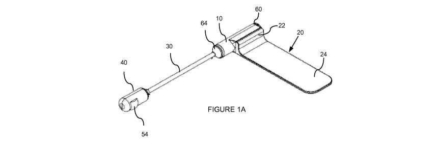
[0023] Figure 1A illustrates an assembled perspective view of a booklight for
an e-Reader according to an embodiment;
[0024] Figure 1 B illustrates an exploded view of the booklight of Figure 1A;
[0025] Figure 2A-2D illustrate assembled perspective views of the booklight of
Figures 1A and 1 B;
6
CA 02746853 2011-06-14
WO 2010/080553 PCT/US2009/068598
[0026] Figures 3A-3D illustrate perspective views of a cover assembly
including the booklight of Figure 1A assembled with a protective cover for an
eReader;
[0027] Figures 4A-4E illustrates an exploded and assembled view of a base
tab of a booklight for an e-Reader according to an embodiment;
[0028] Figures 5A-5E illustrates an exploded and assembled view of a base of
a booklight for an e-Reader according to an embodiment;
[0029] Figures 6A-6C illustrate partial perspective of a base and base tab
according to an embodiment;
[0030] Figures 7A-7C illustrate a contact bar of a booklight according to an
embodiment;
[0031] Figures 8A-8D illustrate a first cap of a booklight according to an
embodiment;
[0032] Figures 9A-9D illustrate a negative battery contact of a booklight
according to an embodiment;
[0033] Figures 10A-10D illustrate a second cap of a booklight according to an
embodiment;
[0034] Figures 11A-11D illustrate a positive battery contact of a booklight
according to an embodiment;
[0035] Figures 12A-12C illustrate a manipulatable neck of a booklight
according to an embodiment;
[0036] Figure 13A illustrates an assembled view of a light assembly housing
of a booklight according to an embodiment;
[0037] Figure 13B illustrates an exploded view of the light assembly housing
of Figure 13A;
7
CA 02746853 2011-06-14
WO 2010/080553 PCT/US2009/068598
[0038] Figures 14A-14D illustrate views of a first side of a light assembly
housing of Figure 13A.
[0039] Figures 15A-15D illustrate views of a second side of a light assembly
housing of Figure 13A.
[0040] Figure 16A-16B illustrate an assembled and exploded view of a printed
circuit board (PCB) assembly of a booklight according to an embodiment;
[0041] Figures 17A-17E illustrate views of a reflector a booklight according
to
an embodiment;
[0042] Figures 18A-18D illustrate views of an optical lens of a booklight
according to an embodiment; and
[0043] Figures 19A-19D illustrate views of a switch cover of a booklight for
an
e-Reader according to an embodiment.
DETAILED DESCRIPTION
[0044] The present invention now is described more fully hereinafter with
reference to the accompanying drawings, in which embodiments of the invention
are
shown. This invention may, however, be embodied in many different forms and
should not be construed as limited to the embodiments set forth herein;
rather, these
embodiments are provided so that this disclosure will be thorough and
complete, and
will fully convey the scope of the invention to those skilled in the art.
[0045] Referring now to the drawings, Figures 1A-19D illustrate exemplary
aspects of a booklight for an eReader.
[0046] As shown in Figures 1A-3D, an exemplary embodiment is directed to a
booklight for a protective cover for an eReader. The exemplary booklight can
be
8
CA 02746853 2011-06-14
WO 2010/080553 PCT/US2009/068598
configured to work seamlessly and integrally with the protective cover of the
eReader.
[0047] The exemplary booklight comprises a base, a light assembly housing
40 having a light source, a manipulatable neck 30 coupled between the base and
the
light housing assembly, and a base tab 20 rotatably coupled to the base. The
base
tab 20 can includes a first end 22 rotatably coupled to the base tab 20, and a
second
end 24 extending from the first end 22. As shown in Figure 1A, the second end
24 is
a free end 24. At least a portion of the free end 24 is configured to engage a
pocket
of the protective cover, as shown for example in Figure 3A.
[0048] The light assembly housing 40, base 10, and base tab 20 can be
constructed from lightweight durable ABS plastic or other suitable materials.
The
manipulatable neck 30 can be formed from plastic, metal, or other suitable
materials.
[0049] A size and shape of a perimeter of the portion of the free end 24
substantially corresponds to a size and shape of the pocket of the protective
cover.
In an exemplary embodiment, the free end 24 includes a substantially flat
plate
portion configured to engage the pocket of the protective cover. In other
embodiments, the base tab 20 can have other shapes, such as a rod-shape, a
wire-
shape, a wire-shape configured to form a perimeter surface corresponding to
the
shape of the pocket, etc.
[0050] As illustrated in Figures 2A-2D, the base tab 20 can be rotatable about
an axis of rotation that is transverse to the longitudinal axis of the base
10. For
example, in an exemplary embodiment, the first end 22 of the base tab 20 can
be
rotatably coupled to the base 10 by a swivel joint. In another exemplary
embodiment, the first end 22 of the base tab 20 can be rotatably coupled to
the base
by a ball and socket joint.
9
CA 02746853 2011-06-14
WO 2010/080553 PCT/US2009/068598
[0051] An exemplary embodiment of a protective cover 100 for an eReader is
illustrated in Figures 3A-3D. The protective cover 100 can include, for
example, a
pocket for supporting the booklight. For example, the protective cover 100 can
include a pocket 120 for receiving the base tab 20 of the booklight such that
the
booklight can be easily and effortlessly carried with the eReader, for
example, at all
times. The pocket 120 can be formed, for example, at an upper end of the
interior
surface of the rear cover 104 such that the book light can be positioned to
extend
from the upper end of the spine toward the lower end of the spine of the
cover. In
other embodiments, the pocket 120 can be formed at other locations on the
interior
of the rear cover 104, or at locations on the interior of the front cover 102.
The
pocket 120 can be formed on the same cover as the mounting system or on a
different cover than the cover having the mounting system.
[0052] The pocket 120 can be integrally formed or sewn into the interior
surface of the cover or coupled to the interior surface of the cover, for
example, by
another adhering means, such as using a glue, adhesive tape, etc.
[0053] The pocket 120 includes an open end 120a adjacent to the spine of the
protective cover 100 for receiving the base tab 20 of a booklight. The pocket
120
can include a closed end 120b at an opposite end from the open end 120a. In
other
embodiments, both ends of the pocket can be open ends. A shape of the pocket
120 can be configured to correspond to a shape of the base tab 20 of the
booklight.
[0054] As shown in Figure 3B, in operation, the base tab 20 of the booklight
can be inserted into the pocket 120 until the booklight is positioned along
the spine
of the protective cover 100, thereby securing the booklight to the protective
cover. In
this manner, the protective cover 100 can seamlessly integrate and store the
booklight within the protective cover 100 in the spine of the cover when the
cover
CA 02746853 2011-06-14
WO 2010/080553 PCT/US2009/068598
100 is in the closed position. In this way, the present invention provides a
protective
cover 100 including an integral booklight that is compact and portable.
[0055] When the cover 100 is in the flat open position or the full open
position,
the light assembly housing 40 can be moved into a position to illuminate the
display
of the eReader in several ways. For example, the light assembly housing 40 can
be
moved into position to illuminate the display of the eReader by flexing or
bending the
manipulatable neck 30 of the booklight while the booklight is in the stored
position.
Additionally, as shown in Figure 3B, the booklight can be pivoted or swiveled
about
the base tab 20, thereby moving the booklight from a stored position in which
the
booklight is aligned with the spine of the cover 100 and into an open position
in
which at least a portion of the booklight extends away from the cover 100 such
that
the booklight can be positioned to light the display of the eReader. The
flexible neck
30 then can be moved into an optimal position to focus the light and
illuminate the
display of the eReader by flexing or bending the manipulatable neck 30 of the
booklight while the booklight is in the open (i.e., pivoted or swiveled)
position. The
booklight can be pivoted or swiveled into numerous positions, depending on the
desired position of the light housing assembly for illuminating the display of
the
eReader. The cover assembly of the booklight and the protective cover will be
described in greater detail below.
[0056] With reference to Figures 4A-4E and 5A-5E, the base tab 20 and the
base 10 of the booklight will now be described.
[0057] The base tab 20 can have a substantially L-shaped cross-section. In
this embodiment, the free end 24 is substantially perpendicular to the fixed
end. The
first end 22 of the base tab 20 can include a front face on a side of the free
end 24,
and a rear face on an opposite side from the free end 24. As shown in Figure
4D,
11
CA 02746853 2011-06-14
WO 2010/080553 PCT/US2009/068598
the first end 22 of the base tab 20 includes a surface having a first slot 26
formed
therein. For example, the rear face of the base tab 20 can include the first
slot 26.
[0058] As shown in Figure 5A, the body includes a base tab 20 mounting
surface upon which the first end 22 of the base tab 20 can be rotatably
coupled. The
base tab 20 mounting surface can include a first protrusion 12 that
corresponds to
and engages the first slot 26 of the first end 22 of the base tab 20 in a
manner such
that the base tab 20 pivots about the first protrusion 12.
[0059] In the exemplary embodiment of Figures 5A-5E, the first protrusion 12
has a first portion having a first diameter and a second portion having a
second
diameter. The second portion interposes the base tab 20 mounting surface and
the
first portion. The first diameter of the first portion is greater than the
second diameter
of the second portion.
[0060] In the exemplary embodiment of Figures 4A-4E, the first slot 26 of the
base tab 20 includes a first opening portion having a dimension that is one of
equal
to and greater than the first diameter of the first portion of the protrusion
12. The first
slot 26 of the base tab 20 can include a second opening portion having a
dimension
that is one of equal to and greater than the second diameter of the second
portion of
the protrusion and less than the first diameter of the first portion of the
protrusion 12.
[0061] As illustrated in Figures 6A-6C, the first slot 26 can be open at one
end
and closed at the other end such that the protrusion 12 of the base tab 20 can
be
inserted into the larger diameter, open portion of the first slot 26 and moved
into
engagement with the smaller diameter, closed portion of the first slot 26.
Alternatively, the first slot 26 can be closed at both ends, with one end
having a
larger diameter than the other end such that the protrusion 12 of the base tab
20 can
be inserted into the larger diameter portion of the first slot 26 and moved
into
12
CA 02746853 2011-06-14
WO 2010/080553 PCT/US2009/068598
engagement with the smaller diameter portion of the first slot 26. In this
manner, the
protrusion 12 can be seated in the first slot 26 such that the base tab 20
pivots or
swivels about the first protrusion 12 of the base 10.
[0062] It is noted that in another embodiment, the first slot 26 can be formed
on the base 10 and the protrusion 12 can be formed on the base tab 20.
[0063] One of ordinary skill in the art will recognize that other arrangements
for pivoting or swiveling the base tab 20 with respect to the base 10 are
possible and
are contemplated by the present application. For example, in another exemplary
embodiment, the protrusion 12 can be a ball and the slot can be a socket for
receiving the ball. In an exemplary embodiment, the socket can include
flexible
portions or fingers that flex or separate to receive the ball and then return
to their
original position to retain the ball in the socket.
[0064] With reference again to Figures 4A-4E and 5A-5E, in another
embodiment, the surface of the first end 22 of the base tab 20 can include a
second
slot (e.g., 27) formed therein and adjacent to the first slot. The base tab 20
mounting
surface can include a second protrusion (e.g., 14) that engages the second
slot (e.g.,
27) of the first end 22 when the base tab 20 is in a first pivot position, and
does not
engage the second slot (e.g., 27) of the first end 22 when the base tab 20 is
in a
pivot second position.
[0065] In the illustrated embodiment, the surface of the first end 22 of the
base
tab 20 includes a second slot 27 and a third slot 28 formed therein and
adjacent to
the first slot 26. The first slot 26 interposes the second slot 27 and the
third slot 28.
In this embodiment, the base tab 20 mounting surface includes a second
protrusion
14 and a third protrusion 16 that engage respectively the second slot and the
third
slot of the first end 22 when the base tab 20 is in a first pivot position.
The second
13
CA 02746853 2011-06-14
WO 2010/080553 PCT/US2009/068598
protrusion and a third protrusion do not engage the second slot and the third
slot of
the first end 22 when the base tab 20 is in a second pivot position. In this
manner,
the base tab 20 can be retained in the closed position by the engagement of
the
second protrusion 14 and a third protrusion 16 with the second slot 27 and the
third
slot 28. By disengaging the protrusions 14, 16 from the slots 27, 28, the base
tab 20
can be pivoted or swiveled into an un-stored position.
[0066] With reference again to Figures 5A-5E, the body can include a battery
compartment configured to secure a battery 68 therein. The battery compartment
includes an electrically conductive terminal, such as a contact bar 18, for
electrically
contacting the ends of the battery 68. An exemplary embodiment of the contact
bar
18 is illustrated in Figures 7A-7C.
[0067] The exemplary embodiment can use, for example, a single standard
AAA alkaline battery 68 which may provide endurance enough for more than 20
hours of operation of the light source. In other embodiments, other types and
sizes
of batteries can be used.
[0068] One of ordinary skill in the art will recognize that the embodiments
are
not limited to the battery 68 being stored in the base 10. In other
embodiments, the
battery 68 can be included in the light assembly housing 40 or another
component.
[0069] The first end of the body 10 can include a first end cap 60 movable
between an open position for accessing the battery compartment and a closed
position for securing the battery 68 in the battery compartment. An exemplary
embodiment of the first cap 60 is illustrated in Figures 8A-8D. The first end
cap 60
can include a negative battery contact or terminal 62 as illustrated in
Figures 9A-9D.
[0070] A second end of the body 10 can include a second end cap 64 that
couples a first end of the manipulatable neck 30 to the second end of the body
10.
14
CA 02746853 2011-06-14
WO 2010/080553 PCT/US2009/068598
An exemplary embodiment of the second end cap 64 is illustrated in Figures 1OA-
10D. The second end cap 64 can include a positive battery contact or terminal
66 as
illustrated in Figures 11A-11 D.
[0071] Figures 12A-12C illustrate a manipulatable neck 30 according to an
embodiment of the invention. The manipulatable neck 30 can be manipulatable
between a plurality of positions. The manipulatable neck 30 can be a flexible
and
resilient neck 30. The manipulatable neck 30 can be configured in numerous
positions and is capable of retaining the manipulated position such that the
light
assembly housing 40 can be placed in an optimal position for illuminating the
display
of the eReader. In other embodiments, the manipulatable neck 30 can be formed
from a series of links that are rotatable or pivotable with respect to each
other.
[0072] In the illustrated embodiment, the manipulatable neck 30 includes a
conductor extending along a length of the manipulatable neck 30. The first end
of
the conductor is electrically connected to the electrically conductive
terminal (e.g.,
18) of the body 10 and a second end of the conductor is electrically connected
to a
power input of the light assembly housing 40. The manipulatable neck 30 can be
a
hollow manipulatable neck 30 such that the conductor can extend along the
length of
the manipulatable neck 30 inside the hollow manipulatable neck 30.
[0073] With reference to Figures 13A-19D, an exemplary embodiment of a
light assembly housing 40 will now be described.
[0074] As shown in Figures 13B, 14A-14D, and 15A-15D, an exemplary
embodiment of the light assembly housing 40 can be formed by a first side 42
having
a light source 50, and a second side 44 having a switch 56 for the light
source 50.
The light source 50 can include an incandescent light or a light emitting
diode (LED),
such as a SuperBright LED light. A printed circuit board 51 having the light
source
CA 02746853 2011-06-14
WO 2010/080553 PCT/US2009/068598
50 mounted thereon, as illustrated for example in Figures 13B and 16A-16B, can
be
secured inside the light assembly housing 40.
[0075] With reference again to Figures 13B and 14A-14D, the first side 42 of
the light assembly housing 40 can include an outer surface having an opening
46
formed therein. The light source 50 is disposed adjacent to the opening 46 and
configured to emit light in a direction away from the light assembly housing
40. As
explained above, the light source 50 can include a light emitting diode (LED).
[0076] As shown in Figures 13B and 17A-17E, an exemplary embodiment of
the light assembly housing 40 can include a mirrored reflector 52 disposed
adjacent
to the opening 46 and configured to reflect and focus light emitted from the
light
source 50 in the direction away from the light assembly housing 40. As shown
in
Figures 13B and 18A-D, the light assembly housing 40 can include an optical
lens 54
disposed one of in and over the opening 46 and along a light path of the light
emitted
from the light source 50. The optical lens 54 can include, for example, a dome-
shaped optical lens (e.g., an optical quality dome lens). The lens 54 is not
limited to
a dome-shaped lens and lenses having other shapes and sizes are contemplated
by
the embodiments. The optical lens 54 can be selected to uniformly distribute
the
light emitted from the light source 50 in the direction away the light
assembly housing
40.
[0077] As shown in Figures 13B and 19A-19D, the light assembly housing 40
can include a switch 56 for selecting among a plurality of light settings for
the light
source 50.
[0078] As shown in the exemplary embodiment of Figures 19a-19D, the switch
56 can be a slidable switch or slidable switch cover, such as a three-position
switch,
being selectable between a plurality of light intensity settings, such as a
`high'
16
CA 02746853 2011-06-14
WO 2010/080553 PCT/US2009/068598
setting, a `low' setting, and an `off' setting. Each of the light intensity
settings causes
the light source 50 to emit a different level or quantity of light.
[0079] In other embodiments, the switch can be a toggle switch, a rotatable
switch or knob, or a push button switch etc. having a plurality of light
intensity
settings, such as a `high' setting, a `low' setting, and an `off' setting.
[0080] The embodiments are not limited to these light intensity settings. In
other embodiments, the switch 56 can include a plurality of `high' settings
and/or a
plurality of `low' settings. For example, the plurality of light settings for
the light
source 50 includes an `off' setting and at least two light intensity settings.
In another
embodiment, the plurality of light settings for the light source 50 includes
an `off'
setting and at least three light intensity settings.
[0081] As illustrated in the exemplary embodiment of Figure 13A, the switch
56 can be on the light assembly housing 40. In another embodiment (not shown),
the switch can be on the base 10 and electrically connected to the light
source 50 via
an electrical conductor or wire extending from the base 10, through or along
the
manipulatable neck 30, and into the light assembly housing 40.
[0082] In another embodiment, a booklight for a protective cover for an
eReader, wherein the protective cover includes a pocket for supporting the
booklight,
can include a base 10, a light assembly housing 40 having a light source, a
manipulatable neck 30 coupled between the base 10 and the light assembly
housing
40, and a base tab 20 coupled to the base 10. The base tab 20 includes a first
end
22 coupled to the base tab 20, and a second end 24 extending from the first
end 22,
wherein the second end 24 is a free end, and wherein at least a portion of the
free
end 24 is configured to engage the pocket of the protective cover.
17
CA 02746853 2011-06-14
WO 2010/080553 PCT/US2009/068598
[0083] In this embodiment, the base tab 20 is not pivotable with respect to
the
base 10 of the booklight. In operation, the base tab 20 of the booklight is
inserted
into the pocket until the booklight lies along the spine of the protective
cover, as
shown for example in Figure 3B. In this embodiment, the light assembly housing
40
can be moved into a position to illuminate the display of the eReader by
flexing or
bending the manipulatable neck 30 of the booklight while the booklight is in
the fixed,
stored position.
[0084] With reference again to Figures 3A-3D, another exemplary
embodiment is directed to a cover assembly for an eReader, wherein the cover
assembly includes a protective cover 100, and a booklight 200 removably
secured to
the protective cover. The protective cover 100 includes a first cover 104
having an
interior and an exterior surface, a second cover 102 having an interior and an
exterior surface, a spine connecting the first cover 104 to the second cover
102,
wherein the first cover 104 and the second cover 104 are pivotable with
respect each
other about the spine, a mounting device 114a-c, 116 for securing the eReader
on
the interior surface 104a, 102a of one of the first cover 104 and the second
cover
102, and a booklight pocket 120 on the interior surface 104a, 102a of one of
the first
cover 104 and the second cover 102. The booklight comprises a base 10, a light
assembly housing 40 having a light source 50, a manipulatable neck 30 coupled
between the base 10 and the light assembly housing 40, and a base tab 20
coupled
to the base 10. The base tab 20 includes a first end 22 coupled to the base
tab 20,
and a second end 24 extending from the first end 22, wherein the second end 24
is a
free end, and wherein at least a portion of the free end 24 engages the
booklight
pocket of the protective cover, thereby removably securing the booklight 200
to the
protective cover 100.
18
CA 02746853 2011-06-14
WO 2010/080553 PCT/US2009/068598
[0085] A size and shape of a perimeter of the portion of the free end 24
substantially corresponds to a size and shape of the booklight pocket 120 of
the
protective cover 100. As explained above, the free end 24 includes a
substantially
flat plate portion that engages the booklight pocket 120 of the protective
cover. In
the exemplary embodiment, each of the mounting device 114a-c, 116 and the
booklight pocket 120 are on the first cover 104. In this embodiment, the
mounting
device 114a-c, 116 secures the eReader over the booklight pocket 120 and the
portion of the free end 24 of the base tab 20 when the eReader is secured to
the
interior surface 104a, 102a of the one of the first cover 104 and the second
cover
102. In this manner, the mounting device 11 4a-c, 116 and the eReader secure,
or at
least help to secure, the base tab 20 of the booklight 200 in the booklight
pocket 120
of the protective cover 100, thereby strengthening the assembly of the
protective
cover 100 and the booklight 200.
[0086] In other embodiments, the mounting device 114a-c, 116 and the
booklight pocket 120 can be on separate covers 104 or 102.
[0087] As shown in Figure 3A, the booklight pocket 120 is located adjacent to
an upper end of the interior surface 104a, 102a of the one of the first cover
104a and
the second cover 102. In this manner, the base 10, the manipulatable neck 30,
and
the light assembly housing 40 of the booklight 200 can be configured to be
aligned
serially along the spine of the protective cover 100 in a stored position
inside the
protective cover 100. The light assembly housing 40 can be easily and
conveniently
manipulated into position and/or the base 10 can be pivoted or swiveled into
position, to focus the light from the booklight 200 and optimize the
illumination of the
display of the eReader.
19
CA 02746853 2011-06-14
WO 2010/080553 PCT/US2009/068598
[0088] The present invention has been described herein in terms of several
preferred embodiments. However, modifications and additions to these
embodiments will become apparent to those of ordinary skill in the art upon a
reading of the foregoing description. It is intended that all such
modifications and
additions comprise a part of the present invention to the extent that they
fall within
the scope of the several claims appended hereto.
[0089] Like numbers refer to like elements throughout. In the figures, the
thickness of certain lines, layers, components, elements or features may be
exaggerated for clarity.
[0090] The terminology used herein is for the purpose of describing particular
embodiments only and is not intended to be limiting of the invention. Unless
otherwise defined, all terms (including technical and scientific terms) used
herein
have the same meaning as commonly understood by one of ordinary skill in the
art
to which this invention belongs. It will be further understood that terms,
such as
those defined in commonly used dictionaries, should be interpreted as having a
meaning that is consistent with their meaning in the context of the
specification and
relevant art and should not be interpreted in an idealized or overly formal
sense
unless expressly so defined herein. Well-known functions or constructions may
not
be described in detail for brevity and/or clarity.
[0091 ] As used herein, the singular forms "a", "an" and "the" are intended to
include the plural forms as well, unless the context clearly indicates
otherwise. It will
be further understood that the terms "comprises" and/or "comprising," when
used in
this specification, specify the presence of stated features, integers, steps,
operations, elements, and/or components, but do not preclude the presence or
addition of one or more other features, integers, steps, operations, elements,
CA 02746853 2011-06-14
WO 2010/080553 PCT/US2009/068598
components, and/or groups thereof. As used herein, the term "and/or" includes
any
and all combinations of one or more of the associated listed items. As used
herein,
phrases such as "between X and Y" and "between about X and Y" should be
interpreted to include X and Y. As used herein, phrases such as "between about
X
and Y" mean "between about X and about Y." As used herein, phrases such as
"from
about X to Y" mean "from about X to about Y."
[0092] It will be understood that when an element is referred to as being
"on",
"attached" to, "connected" to, "coupled" with, "contacting", etc., another
element, it
can be directly on, attached to, connected to, coupled with or contacting the
other
element or intervening elements may also be present. In contrast, when an
element
is referred to as being, for example, "directly on", "directly attached" to,
"directly
connected" to, "directly coupled" with or "directly contacting" another
element, there
are no intervening elements present. It will also be appreciated by those of
skill in
the art that references to a structure or feature that is disposed "adjacent"
another
feature may have portions that overlap or underlie the adjacent feature.
[0093] Spatially relative terms, such as "under", "below", "lower", "over",
"upper", "lateral", "left", "right" and the like, may be used herein for ease
of
description to describe one element or feature's relationship to another
element(s) or
feature(s) as illustrated in the figures. It will be understood that the
spatially relative
terms are intended to encompass different orientations of the device in use or
operation in addition to the orientation depicted in the figures. For example,
if the
device in the figures is inverted, elements described as "under" or "beneath"
other
elements or features would then be oriented "over" the other elements or
features.
The device may be otherwise oriented (rotated 90 degrees or at other
orientations)
21
CA 02746853 2011-06-14
WO 2010/080553 PCT/US2009/068598
and the descriptors of relative spatial relationships used herein interpreted
accordingly.
22