Note: Descriptions are shown in the official language in which they were submitted.
CA 02746885 2011-06-15
WO 2010/069032
PCT/CA2008/002220
RAMP FOR EVACUATION DEVICE
FIELD OF THE INVENTION
The present invention relates to an evacuation device for vehicles, and
more particularly to a ramp for such an evacuation device.
BACKGROUND ART
In passenger ground vehicles such as trains, it is known to provide an
emergency evacuation ramp which can be easily actuated by passengers in case
of
emergency to exit the vehicle quickly. Such ramps are sometimes integrated
with
an emergency door of the vehicle to automatically deploy when the door is
opened.
However, emergency ramps integrated with doors often either block a space
where
a window of the door would otherwise be provided, and as such reduce the
vision
area of the operator and/or the passengers, may have a relatively complex
deploy-
ment motion that increases the probability of malfunction during deployment,
and/or necessitate a relatively complex manufacturing and installation
process.
SUMMARY OF INVENTION
It is therefore an aim of the present invention to provide an improved
ramp for an evacuation device.
Therefore, in accordance with the present invention, there is provided a
foldable ramp for evacuation of a vehicle, the ramp comprising two spaced
apart
primary side members each having a first end hingedly connectable to a frame
attached to the vehicle and a second end opposed the first end, two secondary
side
members, each of the secondary side members having opposed first and second
ends, the second end of each secondary side member being connected to the
second
end of a respective one of the primary side members, a primary flipping panel
extending between the primary side members and having a first end pivotally
connected to the primary side members and a second end free from the side
members, a secondary flipping panel extending between the secondary side
members and having a first end pivotally connected to the secondary side
members
and a second end free from the side members, the second end of the secondary
flipping panel being hingedly connected to the second end of the primary
flipping
panel, and a fixed panel extending between one of the primary side members and
the secondary side members, the fixed panel being fixedly attached to the one
of
the primary and secondary side members adjacent the first ends thereof, the
fixed
CA 02746885 2011-06-15
WO 2010/069032
PCT/CA2008/002220
panel being adjacent the first end of the flipping panel connected to the one
of the
primary and secondary side members, wherein the ramp is configurable between a
folded and a deployed position, the panels in the deployed position forming a
ramp
surface for evacuation of the vehicle, and the panels in the folded position
being
s stacked one against the other.
Also in accordance with the present invention, there is provided an
evacuation device for a ground vehicle, the evacuation device comprising such
a
ramp, the frame defining a door opening, a door connected to the frame through
hinges such as to be pivotable between a closed position where the door blocks
the
door opening and an opened position where a free end of the door is pivoted
away
from the vehicle, the ramp in the folded position allowing the door to close
thereover.
Also in accordance with the present invention, there is provided a door
assembly for an evacuation device of a ground vehicle, the door assembly
comprising a door, a locking mechanism including a rotating cam and lock rods
extending therefrom to actuate a latch selectively locking and unlocking the
door
with a corresponding frame, and an inflatable seal extending around the door
and
sealing a space between the door and the frame when the door is a closed
position,
the inflatable seal being connected to a source of pressurized air through a
valve,
the locking mechanism in a locked position being actuated toward an unlocked
position through rotation of the cam, the rotating cam actuating the valve
before
actuating the latch, the valve upon actuation releasing air pressure in the
inflatable
seal.
Further in accordance with the present invention, there is provided an
evacuation device for a ground vehicle, the device comprising a frame module
defining a door opening, a door connected to the frame module through hinges
such as to be pivotable between a closed position where the door blocks the
door
opening and an opened position where a free end of the door is pivoted away
from
the vehicle, a deployable ramp pivotally connected to the frame module
adjacent a
threshold thereof, the ramp being movable between a retracted and a deployed
position, and biased to be deployed when in the retracted position, a drum
rotation-
ally mounted in a fixed position with respect to the frame module, the drum
being
engaged with a rope wound therearound and attached to the ramp, the rope
retain-
ing the ramp in the retracted position when the drum is prevented from
rotating, a
gear functionally connected to the drum such as to rotate therewith, a ratchet
mechanism biased to engage the gear, the ratchet mechanism being movable
- 2 -
CA 02746885 2011-06-15
WO 2010/069032
PCT/CA2008/002220
between an engaged position in engagement with the gear, and a release
position
free of the gear, the ratchet mechanism in engagement with the gear preventing
the
drum from rotating in a direction corresponding to the ramp being deployed
while
allowing the drum to rotate in the opposite direction, and a latch mechanism
attached to the door or to an element moving with the door, the latch
mechanism
being in engagement with the ratchet mechanism such that an opening motion of
the door moves the latch mechanism which moves the ratchet mechanism away
from the engaged position, the latch mechanism moving the ratchet mechanism to
the release position when the door has reached a given position away from the
io closed position.
BRIEF DESCRIPTION OF THE DRAWINGS
Reference will now be made to the accompanying drawings, showing
by way of illustration a particular embodiment of the present invention and in
which:
Fig. 1 is an exploded perspective view of an evacuation device accord-
ing to a particular embodiment of the present invention;
Fig. 2 is an end view of a train cab incorporating the evacuation device
of Fig. 1;
Fig. 3 is a perspective view of a door assembly of the evacuation
device of Fig. 1;
Fig. 4 is a partial cross-sectional view of the door assembly of Fig. 3,
showing a locking mechanism thereof;
Figs. 5A and 5B are partial rear view of the door assembly of Fig. 3 is
showing part of the locking mechanism of Fig. 4, the locking mechanism being
in
an unlocked position in Fig. 5A and in a locked position in Fig. 5B;
Fig. 6 is a perspective view of part of a ramp of the evacuation device
of Fig. 1;
Fig. 7 is a partial perspective view of an underside of a ramp of the
evacuation device of Fig. 1;
Fig. 8 is a different partial perspective view of the ramp of Fig. 7;
Fig. 9 is a side cross-sectional view of a frame and ramp assembly of
the evacuation device of Fig. 1 shown with the ramp in a folded position;
Figs. 10A and 10B are side views of part of an exterior release mecha-
nism, shown in an activated position in Fig. 10A and in a standby position in
Fig.
10B;
- 3 -
CA 02746885 2015-01-16
Fig. 11 is a perspective view of a header assembly of the evacuation
device of Fig. 1;
Fig. 12 is a side view of a ratchet mechanism and part of a winch
assembly of the header assembly of Fig. 11;
Figs. 13A-13H are perspective views of the evacuation device of Fig. 1
showing a progression of a deployment of the ramp thereof;
Fig. 14 is a perspective partial view of the ramp of the evacuation
device of Fig. 1, showing the engagement of a gripping mechanism therewith
prior
to retraction of the deployed ramp; and
Figs. 15A-15B are partial front views of the header assembly of Fig.
11, showing the engagement and retraction of latch mechanism thereof with the
ratchet mechanism of Fig. 12.
DETAILED DESCRIPTION OF THE PARTICULAR EMBODIMENTS
Referring now to Fig.1, an evacuation device according to a particular
embodiment of the present invention is generally shown at 10 and comprises a
door assembly 12 and a frame and ramp assembly 14 which includes a header
assembly 16. In the embodiment shown, the device 10 is designed to be used as
an
emergency evacuation device and be mounted by a train car builder to a new or
existing vehicle at the ends of the front and rear cabs 8, as shown in Fig. 2.
The
frame and ramp assembly 14 is attached to the frame of the vehicle, for
example to
vertically extending collision posts 17 thereof extending on each side of the
door
opening.
The modular configuration advantageously facilitates fabrication,
testing and installation of the evacuation device 10. The interior panels of
the
device 10 are preferably designed to be integrated with the cab interior
design.
In order to provide to the vehicle operator a wide vision area, the frame
and ramp assembly 14 in its folded position provides for a substantially large
opening which overlays at least a major portion of a windshield area 18 of the
door
assembly 12, such that the windshield area 18 is at least substantially
unobstructed
by the frame and ramp assembly 14 in its folded position.
Referring to Fig. 3, the door assembly 12 includes a door 20 which is
preferably, although not necessarily, molded as a single piece. In a
particular
embodiment, the door is made of fiberglass and is reinforced with core cells
and
with pockets to prevent the door from bending under the applied load.
- 4 -
CA 02746885 2011-06-15
WO 2010/069032
PCT/CA2008/002220
The door assembly 12 also includes an inflatable seal 26 extending
around the door 20 and dust barriers 28 mounted to the perimeter of the door
20 to
prevent ingress of water, dust and others debris in the gap between the door
20 and
outer wall of the cab (not shown). An inner conduit (not shown) extends within
the
door 20 between a pressurized air source and the inflatable seal 26.
The door assembly 12 further includes hinge fixing blocks 30 for
receiving door hinges, gas springs 32, a locking mechanism 34 and an interior
release mechanism 36. All of these elements are mounted to the door 20 in an
adequate manner, for example each through a respective back plate with studs
embedded into the door 20. In a particular embodiment, the hinge fixing blocks
30
are mounted to the door 20 to be adjustable laterally, in order to provide
adjust-
ment of the relative position of the door 20.
The gas springs 32 each have a first end 38 pivotally attached to the
door 20 and a second end 40 pivotally attached to the vehicle in which the
device
10 is installed. The gas springs 32 allow the door 20 to automatically open
once
unlocked. Preferably, at least one of the gas springs 32 blocks at full
extension to
maintain the door 20 opened if a loss of gas pressure occurs. Alternately,
locking
of the door 20 in the opened position can be provided by a separate mechanism,
such as for example a mechanism acting on the door hinges to prevent the door
20
from falling back to the closed position once fully opened.
Referring to Fig. 4, the locking mechanism 34 includes a base plate 42
to which is pivotally mounted a cam 44. The cam 44 interfaces with a return
spring
46 and with first and second release cables 48, 52 respectively connected to
an
exterior lock mechanism 50 actuated by an exterior release mechanism 142 and
to
the interior release mechanism 36, both of which will be described in more
details
further below.
The cam 44 pivotally engages two lock rods 54 extending therefrom.
Each lock rod 54 has one end pivotally connected to the cam 44 and another end
pivotally connected to a latch 56, and is also engaged with a return spring
58. The
return springs 46, 58 thus bias the locking mechanism 34 in the engaged
position
when the door 20 is closed.
Each latch 56 interfaces with a rotatable finger 60 and with a lock
switch 62 which sends a signal that is interrupted by the activation of the
lock
mechanism. Each finger 60 interfaces with a locking pin 144 (see Figs. 10A-B)
mounted on the frame and ramp assembly 14 to produce the locking action.
- 5 -
CA 02746885 2011-06-15
WO 2010/069032
PCT/CA2008/002220
The cam 44 also interfaces with a pneumatic valve 64 which is
connected to the inflatable seal 26 and to an air supply line 66, for example
providing air regulated to approximately 10 psi. The valve 64 includes an
exhaust
port 68.
Referring to Figs. 5A-5B, the door 20 includes an access opening 70 for
accessing the locking mechanism 34 and a slidable access panel 72 closing the
access opening. The access panel 72 is preferably locked by a breakable seal
as a
safety feature. The access opening 70 is defined over the cam 44 which
includes a
handle 74 that can be used to turn the cam 44 to disengage the locking
mechanism
if required. In a particular embodiment, the handle 74 is painted in a bright
color,
for example green, and the access panel 72 includes an opening 76 (see Fig. 3)
through which the handle 74 is visible when the locking mechanism 34 is not
engaged (as shown in Fig. 5A) and not visible when the locking mechanism 34 is
engaged (as shown in Fig. 5B), or the opposite, so that a user can determine
by
looking at the color visible through the opening 76 whether the locking
mechanism
34 is engaged or not.
Thus, upon disengagement of the locking mechanism 34, through
actuation of one of the release mechanisms 36, 142 or rotation of the handle
74, the
rotation of the cam 44 first activates the pneumatic valve 64 to release the
pressure
in the inflatable seal 26, such as to ensure an easy unlocking motion. The
rotation
of the cam 44 then pulls on the lock rods/latches 54, 56 and allows the
fingers 60
to rotate. This allows the locking mechanism 34 to be liberated from the
locking
pins 144 mounted on the frame and ramp assembly 14. The rotation of the cam 44
also activates the lock switch 62 at the same time the door 20 unlocks. The
cam 44
also continues acting on the pneumatic valve 64 to maintain the depressurized
state
of the inflatable seal 26 until the door 20 is closed and locked, to
facilitate the
close and lock action.
Referring back to Fig. 4, the locking mechanism 34 further includes a
close switch cam 78 which interfaces with the frame and ramp assembly 14 and
with a close switch 80, with the close switch 80 being activated when the door
20
is opening or closing in order to monitor the status of the door 20.
Referring back to Fig. 3, in a particular embodiment, the door assembly
12 includes a floodlight 82 located along the bottom of the door 20, which is
acti-
vated by the close switch cam 78 when the door 20 begins its opening motion.
Still referring to Fig. 3, the interior release mechanism 36 includes a
release bar 84 installed on the door 20. The interior release mechanism 36 is
- 6 -
CA 02746885 2011-06-15
WO 2010/069032
PCT/CA2008/002220
activated to disengage the locking mechanism 34 simply by pushing on the
release
bar 84 to pull the second release cable 52 (see Fig. 4) extending through the
door
20. Involuntary activation is prevented with an appropriate type of mechanism,
for
example a pivotable cover 86 that needs to be pivoted upward before the
release
bar 84 can be accessed and depressed. In a particular embodiment, the
pivotable
cover 86 includes a safety feature to prevent it from falling back to its
initial
position once pivoted upward. Such a safety feature can include for example
flat
surfaces on the pivot of the cover 86 allowing the pivot to slide into a
machined
slot of a bracket once the cover 86 is pivoted upward, together with a biasing
o mechanism
maintaining the pivot in the slot, such as to prevent the cover 86 from
pivoting back over the release bar 84.
Referring to Figs. 10A-B, the frame and ramp assembly 14 includes the
exterior release mechanism 142 allowing actuation of the door opening and ramp
deployment from outside of the vehicle. The exterior release mechanism 142
includes an exterior release handle (not shown) which in a particular
embodiment
is mounted in a recess and covered with a frangible cover. The handle is
linked to
an exterior release cable 146. Once the exterior release cable 146 is pulled
through
the handle, as shown in Fig. 10A, it activates a spring-loaded release cam 148
to
which it is connected, and the release cam 148 pushes a sliding shaft 150 out
of a
support plate 152 which also supports the locking pin 144 engaging the locking
mechanism 34. The sliding shaft 150 pushes on the exterior lock link mechanism
50 (see Fig. 4) to pull the first release cable 48 and rotate the cam 44, thus
disen-
gaging the locking mechanism 34 from the locking pin 144 to allow the door 20
to
open.
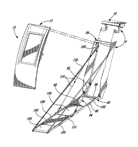
Referring back to Fig. 1, the frame and ramp assembly 14 includes a
frame module 88 which is made for example of bended and welded metal sheets.
The frame and ramp assembly 14 includes a number of components attached to the
frame module 88 such as a ramp 90, dampers 92, 114, ramp linkages 94, the lock-
ing pins 144 interfacing with the locking mechanism 34, the exterior release
mechanism 142, as well as the header assembly 16, to which is attached the
door
assembly 12. The frame module 88 thus links the components of the evacuation
device 10 once installed in the vehicle. The frame module 88 also defines a
ramp
threshold 96 which is preferably covered with an anti-slip finish for improved
safety.
- 7 -
CA 02746885 2011-06-15
WO 2010/069032
PCT/CA2008/002220
The ramp 90 includes two primary side members 98 hingedly connected
to the frame module 88, and two secondary side members 100 each hingedly
connected at the end of a respective one of the primary side members 98.
The ramp 90 also includes primary and secondary fixed ramp panel
102, 104 fixedly attached to the respective pair of side members 98, 100, i.e.
attached thereto such as to move integrally therewith. The primary fixed panel
102
extends between the primary side members 98 adjacent the frame module 88 and
is
attached directly to the primary side members 98, e.g. bolted thereto. The
secon-
dary fixed panel 104 extends between the secondary side members 100 adjacent
their free end and is attached directly to the secondary side members 100,
e.g.
bolted thereto. Alternately, each fixed panel 102, 104 can be provided
integrally as
a single piece together with the corresponding pair of side members 98, 100,
for
example by being integrally molded therewith. As such the two fixed panels
102,
104 are spaced apart from one another and define the two extremities of the
ramp
90.
The ramp 90 further includes primary and secondary flipping ramp
panels 106, 108, which are folded against the fixed panels 102, 104 when the
ramp
90 is folded and which unfold when the ramp 90 is deployed. The primary
flipping
panel 106 extends between the primary side members 98 and has one end
pivotally
connected thereto adjacent the end of the primary fixed panel 102 and another
end
free from the side members 98, 100 and provided with a hinged connection 110,
such as for example a piano hinge. The secondary flipping panel 108 extends
between the secondary side members 100 and has one end pivotally connected
thereto adjacent the end of the secondary fixed panel 104, and another end
free
from the side members 98, 100 and attached to the primary flipping panel 106
through the hinged connection 110. The two flipping panels 106, 108 are thus
hingedly interconnected and define the middle section of the ramp 90. In the
embodiment shown, the hinged connection 110 between the flipping panels 106,
108 is aligned with a hinged connection between the primary and secondary side
members 98, 100, although in an alternate embodiment which is not shown, the
two hinged connections are offset from one another.
In one particular embodiment, the pivot connection between the
flipping panels 106, 108 and the side members 98, 100 are provided through
pins
extending from the flipping panels 106, 108 and received in corresponding
reinforced bores defined in the side members 98, 100.
- 8 -
CA 02746885 2011-06-15
WO 2010/069032
PCT/CA2008/002220
The side members 98, 100 further include stoppers 112 extending there-
from upon which the flipping panels 106, 108 rest when the ramp 90 is deployed
(see Fig. 8). The ramp panels 102, 104, 106, 108, once deployed as in Fig. 1,
provide a flat and uniform walkway surface to evacuate the vehicle when
required.
When the ramp 90 is in the folded position as shown in Fig. 9, the panels 102,
104,
106, 108 are pivoted passed the vertical position and are stacked one against
the
other.
In an alternate embodiment which is not shown, either one the primary
or the secondary fixed panels 102, 104 can be omitted, such that one end of
the
o ramp 90 is defined by one of the flipping panels 106, 108.
In a particular embodiment, the side members 98, 100 are made of
stainless steel and the panels 102, 104, 106, 108 include a layer of honeycomb
type
material sandwiched between two skin panels, made for example of anodized
aluminum. The edges, the sides and the ends of the ramp 90 are marked, for
exam-
ple in yellow, to guide the passengers through the ramp exit path, and the
panels
102, 104, 106, 108 are covered with a slip-resistant finish.
Referring to Fig. 9, the ramp 90 includes spring-loaded arms 136 which
are mounted on each side thereof, and which are spring loaded during the ramp
folding process. Each arm 136 includes a roller 138 at its end which, when the
ramp is folded, engages a spring 140 enclosed in a tube and attached to the
frame
module 88. As such, the ramp 90 is biased toward the deployed position when
folded, and the spring-loaded arms 136 push the ramp 90 over the vertical
position
during the ramp deployment process, when the ramp 90 is released from the
folded
position.
The ramp 90 is preferably self-supporting, such that the ramp 90 does
not rest upon the ground once deployed. In a particular embodiment applied to
a
train cab, the ramp 90, once deployed, forms a maximum angle of 20 with the
horizontal, and stands approximately 12 inches above the ballast to allow an
easy,
fast and safe deployment of the ramp 90 in a variation of rail slopes and
vehicle
suspension conditions, to ensure that the ramp 90 stays over the top of rail
and
provides, in case of emergency, a safe, planar and straight exit walkway to
the
passengers.
Dampers, for example oil dampers, provide for a smooth deployment of
the ramp 90. Referring to Fig. 1, the frame and ramp assembly 14 includes two
primary dampers 92, one of which being attached between the frame module 88
and each primary side member 98 at the hinged connection between the primary
- 9 -
CA 02746885 2011-06-15
WO 2010/069032
PCT/CA2008/002220
side member 98 and the frame module 88. Referring to Fig. 8, the frame and
ramp
assembly 14 also includes two secondary dampers 114 attached between the
primary and secondary flipping panels 106, 108 adjacent the sides thereof,
which
damp the deployment of the secondary portion of the ramp 90. The secondary
dampers 114 are located under the ramp 90 in the deployed position and are
blind
when the ramp 90 is in the folded position.
The frame and ramp assembly 14 further includes two ramp linkages 94
supporting the primary portion of the ramp 90. Each linkage 94 includes two
(2)
pivotally linked rod sections 116, which in a particular embodiment are made
of
stainless steel. Each linkage 94 extends from the upper part of the frame
module 88
to the respective primary side member 98, near the hinged connection between
the
primary side member 98 and the secondary side member 100. Once the ramp 90 is
folded, the linkages 94 fit between the ramp 90 and the frame module 88, as
shown
in Fig. 9.
Referring to Fig. 6, each linkage 94 slidably extends through a sleeve
118 pivotally attached to an arm 120, which is pivotally attached to the
respective
side of the primary flipping panel 106 (see also Figs. 13E-13F) such that the
deploying linkage 94 forces deployment of the primary flipping panel 106
during
deployment of the ramp 90. Alternately, the arm 120 can be pivotally and
slidably
connected to the linkage using any other adequate type of connection, or the
arm
120 can be free from the linkage 94 while coming in contact with the linkage
94
and being pushed thereby during deployment of the ramp 90 to force the deploy-
ment of the primary flipping panel 106.
A compression spring 122 is wound around the linkage 94 between the
sleeve 118 and the end of the linkage 94, such as to be compressed as the ramp
90
is deployed. Referring to Fig. 7, the ramp 90 also includes a flipping panel
lock
124, including for example a pivotable finger 126 supported on the secondary
flipping panel 108 and engaging a pin (not shown) protruding from the adjacent
secondary side member 100 when the flipping panels 106, 108 are fully
deployed.
The ramp 90 under its own weight does not compress the springs 122 enough for
the flipping panels 106, 108 to be fully deployed, and as such the flipping
panel
lock 124 remains disengaged. As the first user walks down the ramp 90, the
weight
of the user compresses the springs 122 until the flipping panels 106, 108
become
fully deployed (i.e. aligned with one another), thus automatically engaging
the
flipping panel lock 124. At the end of the evacuation process and before the
stowing of the ramp 90, the flipping panel lock 124 is manually disengaged by
- 10 -
CA 02746885 2011-06-15
WO 2010/069032
PCT/CA2008/002220
pulling on a lever 128 as indicated by the arrow in the Figure such as to
rotate the
finger 126 out of engagement with the pin, and the compression springs 122
force
the flipping panels 106, 108 out of the fully deployed position.
Referring to Figs. 7 and 14, once the evacuation is over and the flipping
s panel lock 124 is unlocked, a hook-shaped gripping mechanism 130 is
manually
engaged in between the members of the hinged connection 110 before the ramp 90
is folded. The gripping mechanism 130 prevents the flipping panels 106, 108
from
falling back in the fully deployed and thus locked position during the
beginning of
the retraction of the ramp 90. As the ramp 90 progressively folds during
retraction,
o the gripping mechanism 130 is automatically disengaged from the hinged
connec-
tion 110 and is returned to its initial position by a spring 132, such that
the ramp 90
is free to be deployed for its next use.
Referring back to Fig. 1, the frame and ramp assembly 14 further
includes two belts 134 extending from the frame module 88 and each attached at
15 the free end of a respective one of the secondary side members 100, to
act as
handrails for the users of the ramp 90. In a particular embodiment, the belts
134 are
provided in a bright color, and are preferably reflective.
Referring to Fig. 11, the header assembly 16 comprises a header plate
154 defining a top portion of the frame module 88, door mounting blocks 156
and
20 door hinges 158. The header assembly 16 also comprises a rope drum 160
and a
winch assembly 162 linked together by a drive shaft 164. The header assembly
16
is fixed to the vehicle and to a remainder of the frame module 88, for example
with
fasteners.
The door hinges 158 are attached to the mounting blocks 156 with
25 shafts 166, with the mounting blocks 156 being attached directly to the
header
plate 154. In a particular embodiment, the height of the door 20 can be
adjusted by
the addition or removal of shims (not shown) between the blocks 156 and the
header plate 154.1n the embodiment shown, the mounting blocks 156 are adjust-
able from front to rear, and the height of the door 20 is adjusted by the
addition or
30 removal of shims between the blocks 156 and the header plate 154.
The rope drum 160 is rotationally mounted on the header plate 154,
such as to be rotationally mounted in a fixed position with respect to the
frame
module 88. A rope 168 (see Fig. 1) is provided on one side of the ramp 90 for
the
stowing of the ramp 90. The rope 168 is attached to the rope drum 160, passes
35 around the front end of the ramp 90 and is attached under the ramp 90
under the
primary side member 98 near the hinged connection with the secondary side
-11-
CA 02746885 2011-06-15
WO 2010/069032
PCT/CA2008/002220
member 100. The rope 168 under tension retains the ramp 90 passed the vertical
position when the ramp is in the folded position. The rope 168 also allows the
deployed ramp 90 to be folded.
Referring to Figs. 11-12, the winch assembly 162 includes a gear 170
functionally linked to the rope drum 160 through the drive shaft 164 such as
to
rotate simultaneously therewith. A ratchet mechanism 172 is biased, e.g.
through a
spring 174, in an engaged position in engagement with the gear 170. The
ratchet
mechanism 172 in the engaged position prevents the gear 170, and as such the
winch assembly 162 and rope drum 160, from rotating in the direction causing
deployment of the ramp 90, while allowing the gear 170, and as such the winch
assembly 162 and rope drum 160, to rotate in the opposed direction for
retracting
the ramp 90.
The ratchet mechanism 172 is pivotable between the engaged position
and a release position free of the gear 170. Referring to Figs. 12 and 15A,
the
ratchet mechanism 172 includes a release plate 176, and the adjacent door
hinge
158 includes a latch mechanism 178 with a slidable finger 180 in contact with
the
release plate 176. When the door opens, the finger 180 pushes against the
release
plate 176, moving the ratchet mechanism 172 away from the engaged position
with
the gear 170 of the winch assembly 162. The release plate 176 is sized and
posi-
tioned such that at a given position along the opening path of the door 20,
the
finger 180 pushes the ratchet mechanism 172 in the release position where the
ratchet mechanism 172 is disengaged from the gear 170 of the winch assembly
162. The given position preferably corresponds to the fully opened position of
the
door 20 or to a position close thereto. The deployment of the ramp 90 is thus
prevented until the door reaches that given position.
In an alternate embodiment which is not shown, the finger 180 of the
latch mechanism 178 can be provided attached to any adequate element of the
door
assembly 12.
Once the deployed ramp 90 needs to be folded, the finger 180 is pulled
so as to disengage it from the release plate 176, as shown in Fig. 15B, such
that the
spring 174 brings the ratchet mechanism 172 back in engagement with the gear
170 of the winch assembly 162. The winch assembly 162 is activated manually
from the cab interior using a winch crank, which rotates the rope drum 160
through
the drive shaft 164 and thus pulls the ramp 90 with the rope up to the folded
posi-
tion. The winch crank is preferably provided with a torque limiter to avoid
causing
damage and/or compromising the next deployment due to overtorquing. In a
- 12 -
CA 02746885 2011-06-15
WO 2010/069032
PCT/CA2008/002220
particular embodiment, the winch assembly 162 allows the ramp stowing in less
than 5 minutes by a trained person.
The evacuation device 10 is thus used according to the following.
When evacuation is required, the locking mechanism 34 is disengaged,
either by pivoting the cover 86 and pressing the release bar 84 of the
interior
release mechanism 36 (see Fig. 3), by breaking the frangible cover (if
applicable)
and pulling the handle of the exterior release mechanism 142, or by opening
the
access panel 72 of the door assembly 12 and turning the handle 74 of the cam
44
(see Figs. 5A-5B). In all cases, the cam 44 rotates and the locking mechanism
34
o disengages the door 20 from the frame module 88 after the pressure has
been
released from the inflatable seal 26.
Once the locking mechanism 34 is disengaged, the door 20 opens
automatically, under the action of the gas springs 32. The close switch 80 is
acti-
vated by the opening of the door 20, and the floodlight 82 is turned on. Once
the
door 20 is fully opened at least one of the gas springs 32 preferably locks to
prevent the door 20 from falling down.
Once the door 20 has reached the given position allowing the ratchet
mechanism 172 to be released, which is preferably the nearly opened or fully
opened position (see Fig. 13A), the finger 180 of the latch mechanism 178 (see
Figs. 15A-15B) pivots the ratchet mechanism 172 to the release position free
from
the gear 170 of the winch assembly 162, thus releasing the tension in the rope
168.
The spring-loaded arms 136 of the ramp 90, which were engaged with
the springs 140 during the previous folding of the ramp 90 (see Fig. 9), push
the
ramp 90 up to and over the vertical position, as shown in Figs. 13B-13C, thus
causing the automatic deployment of the ramp 90. The motion of the ramp 90 is
not restricted by the belts 134 which extend loosely at this point.
The continued deployment of the ramp 90 is illustrated in Figs 13D-
13G. The ramp 90 deploys under the action of gravity, with the motion being
controlled by the primary and secondary dampers 92, 114. During the
deployment,
the ramp linkages 94 push on the primary flipping panel 106 through the arms
120
to initiate the deployment of the secondary ramp panels 104, 108 (see
particularly
Fig. 13E). The movement of the secondary ramp panels 104, 108 is then stopped
by the hinged connection between the primary and secondary side members 98,
100. The ramp deployment is stopped (See Fig. 13H) by the ramp linkages 94 and
the interaction between the sleeves 118 through which the linkages 94 extend
and
the compression springs 122.
- 13 -
CA 02746885 2011-06-15
WO 2010/069032
PCT/CA2008/002220
During the deployment of the ramp 90, the flipping panels 106, 108
cover the opening which was overlaying the windshield area 18 of the door 20
when the ramp 90 was in the folded position, such as to complete the ramp walk-
way surface. The flipping panels 106, 108 rest against the stoppers 112
extending
from the side members 98, 100.
A single operation, namely the unlocking of the locking mechanism 34,
is thus necessary to cause the complete opening of the door 20 and deployment
of
the ramp 90. In a particular embodiment, the ramp deployment is completed in
less
then one (1) minute.
The passengers are then evacuated, with the flipping panel lock 124
being activated by the weight of the first person walking on the ramp 90.
The deployed ramp 90 is folded and stowed in its folded position, ready
for the next use, according to the following. The flipping panel lock 124 is
manu-
ally unlocked through the lever 128 provided under the ramp 90 (see Fig. 7).
The
gripping mechanism 130, also shown in Fig. 7, is engaged to the hinged
connection
110 between the flipping panels 106, 108, as illustrated in Fig. 14.
Referring to Figs. 15A-15B, the finger 180 of the latch mechanism 178
is pulled and a safety locking pin 182 is inserted in an opening of the finger
180 to
maintain its position. As such, the spring 174 brings the ratchet mechanism
172
back in engagement with the gear 170 of the winch assembly 162.
The winch crank is engaged with the winch assembly 162 and operated.
In a particular embodiment, the winch crank is provided with a mechanism, for
example a small retractable plunger engaging a corresponding hole in the winch
assembly 162, preventing the winch crank from accidentally disengaging from
the
winch assembly 162 during its operation.
The winch assembly 162 is manually operated by pulling and pushing
on the winch crank as per a standard ratchet tool. The winch assembly 162
winds
the rope 168 around the rope drum 160, pulling on the ramp 90 through the rope
168 and automatically folding the ramp linkages 94. The linkages 94 and
intercon-
nection between the ramp panels 102, 104, 106, 108 allow the ramp 90 to fold
in a
manner corresponding to the reverse sequence of the deployment process up to
the
fully folded position. The winch crank is then disengaged from the winch
assembly
162, if necessary by pushing on the plunger retaining it thereto with a
release tool
which in a particular embodiment is removably provided, e.g. screwed, on the
opposed end of the winch crank.
- 14 -
CA 02746885 2015-01-16
The ratchet mechanism 172 engaged to the winch assembly 162 prevents the
ramp 90 from falling back to the deployed position. The gas springs 32 are
unlocked to
allow the door 20 to close. The door 20 is closed from the inside of the
vehicle simply by
pulling on the release bar 84 by hand, until the door 20 reaches its closed
position, and the
locking mechanism 34 is engaged. The closing of the door 20 activates the
close and lock
switches 80, 62, and once the close switch 80 is activated, the floodlight 82
turns off. As
the locking mechanism 34 is engaged, the rotating cam 44 disengages from the
pneumatic
valve 64 and as such allows the inflatable seal 26 to be re-pressurized.
The finger 180 of the latch mechanism 178 is repositioned in engagement with
the release plate 176 of the ratchet mechanism 172 after removal of the safety
locking pin
182, and the cover 86 of the release bar 84 is reset if the interior release
mechanism 36
was used to open the door 20. In a case where the exterior release mechanism
142 was
used to open the door and a frangible cover was broken, such frangible cover
is preferably
replaced.
Advantageously, under condition where low electrical supply or no electrical
power is available, the evacuation device 10 stays fully functional and can be
operated at
anytime.
The embodiments of the invention described above are intended to be
exemplary. Those skilled in the art will therefore appreciate that the
foregoing description
is illustrative only, and that various alternate configurations and
modifications can be
devised without departing from the scope of the present invention.
Accordingly, the
present invention is intended to embrace all such alternate configurations,
modifications
and variances which fall within the scope of the appended claims.
- 15-